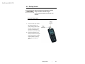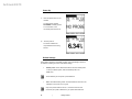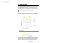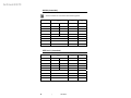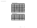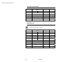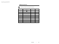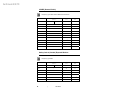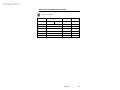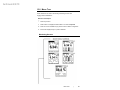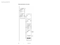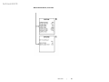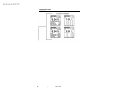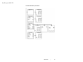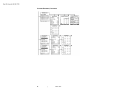
1
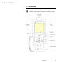
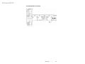
Archived 4/2/10
HI-4460 Graphical Readout
User Manual
Archived 4/2/10
ETS-Lindgren L.P. reserves the right to make changes to any product described
herein in order to improve function, design, or for any other reason. Nothing
contained herein shall constitute ETS-Lindgren L.P. assuming any liability
whatsoever arising out of the application or use of any product or circuit
described herein. ETS-Lindgren L.P. does not convey any license under its
patent rights or the rights of others.
© Copyright 1998–2008 by ETS-Lindgren L.P. All Rights Reserved. No part
of this document may be copied by any means without written permission
from ETS-Lindgren L.P.
Trademarks used in this document: The ETS-Lindgren logo is a trademark of
ETS-Lindgren L.P.; Microsoft and Excel are registered trademarks of Microsoft
Corporation in the United States and/or other countries.
Revision Record | HI-4460 USER'S MANUAL | Part #H-600079, Rev. E
Revision
A
Description
Date
Initial Release
February, 1998
Added upload/download
January, 2000
information
B
Added battery operation
September, 2000
information
C
Updated percent of standards
July, 2001
information
D
Updated upload menu information
November, 2001
E
Updated download information;
September, 2008
rebrand
ii
|
Archived 4/2/10
Table of Contents
Notes, Cautions, and Warnings .............................................. vii 1.0 Introduction .......................................................................... 9 Required Components ................................................................................. 10 ETS-Lindgren Product Information Bulletin ................................................. 10 2.0 Maintenance ....................................................................... 11 Maintenance of Fiber Optics ........................................................................ 11 Service Procedures ..................................................................................... 12 3.0 Specifications..................................................................... 13 Electrical Specifications ............................................................................... 13 Physical Specifications ................................................................................ 13 4.0 Getting Started ................................................................... 15 Connect Components .................................................................................. 15 Power Up ..................................................................................................... 16 Default Settings ........................................................................................... 16 Overview of Screens .................................................................................... 17 Troubleshooting ........................................................................................... 18 HI-4460 Fails to Power On .................................................................. 18 HI-4460 Display Does Not Show Field Level, Displays NO PROBE ... 18 5.0 Keypad Operation .............................................................. 19 Function Keys .............................................................................................. 19 LOG Key ...................................................................................................... 20 Screen Keys ................................................................................................ 20 MODE Keys: Up and Down ................................................................. 20 BACK/ENTER Key and SCREEN/SELECT Key ................................. 21 Specialized Keys ......................................................................................... 21 RANGE ................................................................................................ 21 UNITS .................................................................................................. 21 ESC/CLR ............................................................................................. 22 PWR .................................................................................................... 22 Number Picker ............................................................................................. 22 6.0 Screens ............................................................................... 23 |
iii
Archived 4/2/10
Monitoring Screens ...................................................................................... 23 Logging Screens .......................................................................................... 26 7.0 Menus .................................................................................. 29 MAIN Menu .................................................................................................. 29 PROBE TYPE ...................................................................................... 30 DISPLAY RATE ................................................................................... 30 AXIS ENABLE ..................................................................................... 30 STNDRD .............................................................................................. 30 FREQUENCY UNITS .......................................................................... 30 FREQUENCY ...................................................................................... 30 CONFIG Menu ............................................................................................. 31 CONTRAST ......................................................................................... 31 BACKLIGHT TIME ............................................................................... 31 SCREEN SAVER................................................................................. 31 PASS THRU ........................................................................................ 32 TEMP UNITS ....................................................................................... 32 DOWNLOAD CODE ............................................................................ 32 DATE ................................................................................................... 33 TIME .................................................................................................... 33 ALARM ................................................................................................ 33 AUDIO ................................................................................................. 35 STATUS Menu ............................................................................................. 36 HI-4460 BATTERY .............................................................................. 36 PROBE BATTERY............................................................................... 36 PROBE TEMP ..................................................................................... 36 HI-4460 TEMP ..................................................................................... 36 STORE USED ..................................................................................... 36 STORE UNUSED ................................................................................ 36 PERCENT USED................................................................................. 37 SAMPLE RATE.................................................................................... 37 OPTIONS Menu ........................................................................................... 37 SET TO DEFAULT .............................................................................. 37 FIBER COMM TEST............................................................................ 37 ZERO PROBE ..................................................................................... 38 8.0 Logging ............................................................................... 39 SETUP Menu ............................................................................................... 39 iv
|
Archived 4/2/10
Single Point Logging ............................................................................ 40 Continuous Logging ............................................................................. 41 Periodic Logging .................................................................................. 42 Scheduled Logging .............................................................................. 43 Log Moving Average .................................................................................... 44 REVIEW Menu ............................................................................................. 44 UPLD Menu ................................................................................................. 45 CLEAR Menu ............................................................................................... 47 9.0 Operation ............................................................................ 49 Startup ......................................................................................................... 49 Charging ...................................................................................................... 49 Battery Operation ......................................................................................... 49 Battery Calibration ....................................................................................... 50 Reset ........................................................................................................... 51 Setup ........................................................................................................... 51 10.0 Upload Utility .................................................................... 53 Install Upload Utility ..................................................................................... 53 Start Upload Utility ....................................................................................... 53 Upload Data ................................................................................................. 54 Start Header ........................................................................................ 54 End Header.......................................................................................... 54 Upload Port .......................................................................................... 55 View Data .................................................................................................... 55 11.0 Download Utility ............................................................... 57 Install Download Utility ................................................................................. 57 Start Download Utility .................................................................................. 57 Download the File ........................................................................................ 58 12.0 Standards ......................................................................... 59 Formulas ...................................................................................................... 59 To Calculate Power Density for Electric Fields (Pde) .......................... 59 To Calculate Power Density for Magnetic Fields (Pdh) ....................... 59 To Calculate Electric Fields (E) ........................................................... 59 To Calculate Magnetic Fields (H) ........................................................ 59 ACGIH (Controlled) ...................................................................................... 60 IEEE C95.1 (Controlled) .............................................................................. 60 |
v
Archived 4/2/10
IEEE C95 (Uncontrolled) ............................................................................. 61 FCC (US) (Controlled) ................................................................................. 61 FCC (US) (Uncontrolled) ............................................................................. 62 NRPB (British) ............................................................................................. 62 ICNIRP (Occupational) ................................................................................ 63 ICNIRP (General Public) .............................................................................. 64 Safety Code 6 (Canada) Exposed Workers................................................. 64 Safety Code 6 (Canada) General Public ..................................................... 65 13.0 Menu Tree ......................................................................... 67 Monitoring Screens ...................................................................................... 67 Monitoring Screens, Continued ........................................................... 68 Monitoring Screens, Continued ........................................................... 69 Logging Screens .......................................................................................... 70 Logging Screens, Continued ............................................................... 71 Logging Screens, Continued ............................................................... 72 Logging Screens, Continued ............................................................... 73 Appendix A: Warranty ............................................................. 75 Appendix B: EC Declaration of Conformity .......................... 77 vi
|
Archived 4/2/10
Notes, Cautions, and Warnings
Note: Denotes helpful information intended to
provide tips for better use of the product.
Caution: Denotes a hazard. Failure to follow
instructions could result in minor personal injury
and/or property damage. Included text gives proper
procedures.
Warning: Denotes a hazard. Failure to follow
instructions could result in SEVERE personal injury
and/or property damage. Included text gives proper
procedures.
See the ETS-Lindgren Product Information Bulletin for safety,
regulatory, and other product marking information.
|
vii
Archived 4/2/10
This page intentionally left blank.
viii
|
Archived 4/2/10
1.0 Introduction
See Keypad Operation on page 19 and Screens on page 23 for
complete information on using the keypad and navigating the screens.
Introduction
|
9
Archived 4/2/10
Required Components
The following components are required to install and operate the HI-4460
Graphical Readout:
•
HI-4460 Graphical Readout
•
Fiber optic cable
•
Probe supported by the HI-4460
ETS-Lindgren Product Information Bulletin
See the ETS-Lindgren Product Information Bulletin included with your shipment
for the following:
10
•
Warranty information
•
Safety, regulatory, and other product marking information
•
Steps to receive your shipment
•
Steps to return a component for service
•
ETS-Lindgren calibration service
•
ETS-Lindgren contact information
|
Introduction
Archived 4/2/10
2.0 Maintenance
Before performing any maintenance, follow
the safety information in the ETS-Lindgren
Product Information Bulletin included with
your shipment.
WARRANTY
Maintenance of the HI-4460 is limited to
external components such as cables or
connectors.
If you have any questions concerning
maintenance, contact ETS-Lindgren
Customer Service.
Maintenance of Fiber Optics
Fiber optic connectors and cables can be damaged from airborne particles,
humidity and moisture, oils from the human body, and debris from the connectors
they plug into. Always handle connectors and cables with care, using the
following guidelines.
Maintenance
|
11
Archived 4/2/10
Before performing any maintenance, disconnect
the fiber optic cables from the unit and turn off
power.
When disconnecting fiber optic cables, apply the
included dust caps to the ends to maintain their
integrity.
Before connecting fiber optic cables, clean the
connector tips and in-line connectors.
Before attaching in-line connectors, clean them
with moisture-free compressed air.
Failure to perform these tasks may result in
damage to the fiber optic connectors or cables.
Service Procedures
For the steps to return a system or system component to ETS-Lindgren for
service, see the Product Information Bulletin included with your shipment.
12
|
Maintenance
Archived 4/2/10
3.0 Specifications
Electrical Specifications
Fiber Optic Cable:
200μm, graded index, multimode
Fiber Optic Cable Connector:
Standard FSMA (2)
Battery
7.2 VDC, 140 mAh rechargeable
Battery:
Nickel-Cadmium (NiCd)
Battery Life:
15 hours continuous (full charge)
Battery Charger:
115/230 VAC, approximately
one hour
2.5 mm phone jack
Charger Jack:
Environmental
Operating Temperature:
10°C to 40°C (50°F to 104°F)
Humidity:
Humidity: 5% to 95% relative
humidity, non-condensing
Physical Specifications
Length:
230 mm (9.05 in)
Width:
94 mm (3.70 in)
Weight:
0.72 kg (1.58 lb)
Specifications
|
13
Archived 4/2/10
This page intentionally left blank.
14
|
Specifications
Archived 4/2/10
4.0 Getting Started
Before connecting any components, follow the
safety information in the ETS-Lindgren
Product Information Bulletin included with your
shipment.
Connect Components
1. Connect the fiber optic cable to
the fiber optic ports on the
probe, matching white to white
(transmit) and yellow to yellow
(receive) as indicated by the
markers on the probe and cable.
2. Connect the other end of the
fiber optic cable to the fiber optic
ports on the top of the HI-4460
Graphical Readout, matching
white to white and yellow to
yellow.
Getting Started
|
15
Archived 4/2/10
Power Up
1. Press the power button on the
HI-4460.
The initial screen displays
NO PROBE, indicating a probe
is not connected, or the
connected probe is turned off.
2. Turn the probe on.
The screen indicates the
composite field level is being
sensed.
Default Settings
The HI-4460 is shipped in the default condition, with most settings turned off or
not enabled. Following are some of the default settings:
•
Default probe—The HI-4422 Field Probe is set as the default probe.
To set up a different probe, select the desired probe in the
MAIN menu.
The HI-4460 may be set up with a probe attached.
•
Axis—The default setting is XYZ. This allows data for each axis to be
displayed on the screen or in a log file.
Only some probes read from the X, Y, and Z axes. See the user
manual for your probe to determine if your probe reads three axes.
16
|
Getting Started
Archived 4/2/10
•
Power management—The default setting is turned off.
•
Back light—The default setting is turned off.
•
Screen saver—The default setting is turned off.
•
Logging—The default setting is set to Single point. When the Log key
is pressed, the X, Y, and Z values are logged, as well as the
composite.
Overview of Screens
For a description of each screen, see Screens on page 23. For a description of
the keypad, see Keypad Operation on page 19.
The HI-4460 displays monitoring screens and logging screens. Press the up or
down MODE keys to toggle between the monitoring and logging screens.
•
The monitoring screens display at power up. There are five monitoring
screens; the fifth screen displays when a standard is selected in the
MAIN menu. To cycle through the monitoring screens, press the
BACK/ENTER key or SCREEN/SELECT key.
•
At the bottom of the screen are five menu selections. Press one of the
four function keys below the display on the HI-4460 to select the
indicated menu.
•
Press the BACK/ENTER key or SCREEN/SELECT key to cycle
through the four logging screens. Eight menu selections are available
on the logging screens.
Getting Started
|
17
Archived 4/2/10
Troubleshooting
HI-4460 FAILS TO POWER ON
The battery may be depleted. Connect the battery charger to the charging
connector on the HI-4460 and charge the battery.
HI-4460 DISPLAY DOES NOT SHOW FIELD LEVEL, DISPLAYS
NO PROBE
•
Make sure the fiber optic cable is connected correctly; see
Connect Components on page 15. If the connectors and leads are not
color-coded, connect XMIT on the probe to RECEIVE on the HI-4460,
and RCV on the probe to TRANSMIT on the HI-4460.
18
•
Make sure the probe is turned on.
•
Verify that the probe battery is fully charged.
|
Getting Started
Archived 4/2/10
5.0 Keypad Operation
The HI-4460 Graphical Readout is comprised of two basic user areas, the display
and the keypad. The display is a backlit LCD, and the keypad consists of four
sets of keys. For information on navigating the screens, see Screens on page 23.
For additional information, see Menu Tree on page 67.
The HI-4460 uses a rubber keypad with 13 keys. These keys can be divided into
different groups: function keys, the LOG key, screen keys, and specialized keys.
Function Keys
The four function keys are used to select the submenus displayed at the bottom
of each screen. They are also used for setting specific numeric levels. For more
information on setting specific numeric level, see Number Picker on page 22.
Keypad Operation
|
19
Archived 4/2/10
LOG Key
Toggles the logging function on and off. The default logging function is single
point logging (logging turns off after one reading is taken). Other logging
functions are explained in Logging on page 39.
Screen Keys
MODE KEYS: UP AND DOWN
The up and down MODE keys perform three functions:
•
•
Toggles between the monitoring screens and logging screens.
After a menu function key is pressed, the MODE keys are used to
move up and down through selections.
•
After a selection has been made using the SELECT key, the MODE
keys are used to scroll through selections when only a fixed number of
selections are available.
For items that require a larger range of values, holding down the up or
down MODE key will advance the number by one until it has been
raised or lowered to ten. It will then continue to increase or decrease
by tens, and then by hundreds.
20
|
Keypad Operation
Archived 4/2/10
BACK/ENTER KEY AND SCREEN/SELECT KEY
The BACK/ENTER and SCREEN/SELECT keys perform two functions:
•
•
Scrolls through the monitoring screens and logging screens.
When at a menu screen, the SCREEN/SELECT key is used to select
an item. The BACK/ENTER key is used to save and exit the menu
screen or item.
To exit an item without saving, use the specialized ESC/CLR key. This
will return to the previous value for only that item. Using the ESC/CLR
key to exit the entire menu screen returns to the previous values for all
items.
Specialized Keys
RANGE
Scrolls through the measurement ranges offered by the probe, based on the
UNITS setting. The RANGE key will scroll through all of the possible manual
ranges and the auto range.
UNITS
Scrolls through the units of measurement offered by the probe, based on the
RANGE setting.
Keypad Operation
|
21
Archived 4/2/10
ESC/CLR
•
Clears the PEAK and X, Y, and Z data on the screens, as well as the
averaging buffers.
•
Backs up one level in the menus without saving changes. On menu
screens, pressing the ESC/CLR key moves back one field.
PWR
Turns the unit on and off. The PWR key is also used to turn the back light off (if
not set to OFF in the CONFIG menu).
•
To turn the unit on, quickly press the PWR key.
•
To turn the unit off, press and hold the PWR key.
•
To turn the backlight off, quickly press the PWR key. Pressing any
other key will turn the backlight on again.
Number Picker
The number picker function is available on some menus. When an item
associated with the number picker is selected, the value is highlighted, and the
bottom bar on the screen displays a row of numbers, 0–9.
1.
Press the down MODE key to move the cursor to the bottom of the
screen.
2.
Press the middle two function keys to scroll through the numbers.
When the curser is on the desired number, press the ENTER key to
select the number.
3.
Continue selecting numbers until the desired value is shown in the
field.
Each menu selection that utilizes the number picker function has a
predetermined number of decimal places. When the number entered reaches this
limit, the curser will move back to the menu item. If the number entered is not
valid, it will be set to a minimum or maximum acceptable number. To move the
cursor back to the menu item before it reaches the limit, press the up MODE key.
When the field contains a decimal point, the place is predetermined and the
number must be entered accordingly.
22
|
Keypad Operation
Archived 4/2/10
6.0 Screens
When the HI-4460 Graphical Readout is turned on for the first time, a series of
initial screens display, and then a user screen displays. After the first power on
sequence, the screen that was active when the unit was last turned off will
display.
Following is a description of the monitoring screens and logging screens.
For additional information, see Menu Tree on page 67.
Monitoring Screens
The first screen to display is the monitoring screen.
• Field strength displays at the top
of the screen as a bar graph.
Peak value displays as a thin
vertical line next to the bar graph.
If the bar graph appears blank,
the value is less than the lower
range value. If the bar is
completely filled in, the value is
greater than the upper range
value.
Change to a different range to view the reading. Below the bar graph is a line of
text that shows selected range limits. The lower limit is on the left, the upper
limit is on the right, and the peak value is in the center.
Under the range limits is another line of text that shows the axes that are being
recorded, and the selected range. The axes are on the left side and the
selected range is on the right
An HI-60XX Series Field Probe has only one range. The scale
readings are for the displayed bar graph only. A scheduled log period
will display the word LOG in the center of this line. If the unit is logging
data, the word LOG will flash.
Screens
|
23
Archived 4/2/10
At the bottom of most screens is a list of menus that may be selected using the
four Function keys. Alarm messages are also displayed in this area.
The rest of the screen shows the present field reading in large digits, along with
the units of measure currently selected. When there is no probe attached or the
probe is turned off, this area will display NO PROBE.
The following screens replace this large digit reading with information If
auto range is not selected and the reading does not fall within the selected
range, an over or under range condition occurs. When this happens, the area
showing the reading reports an over range or an under range reading. The over
range or under range value is also shown
Press the BACK/ENTER key or SCREEN/SELECT key to scroll through the
monitoring screens, as shown in the following illustrations.
This shows a plot of the composite
reading with the two horizontal bars
representing the upper and lower
limits of the range selected
This shows a bar graph of each of
the axes being monitored as well as
their values. This screen is not
available if axis enable in the
MAIN menu is set to COMP
(composite).
24
|
Screens
Archived 4/2/10
This shows the bar graphs and the
plot. This screen is not available if
axis enable in the MAIN menu is set
to COMP.
This shows the percent of standard
information. It is displayed only if
Standards is turned on in the
MAIN menu.
The percentage of the standard is
displayed in large numbers, with the
specific standard displayed under the
percentage. The last two lines show
the frequency selected and the
standard value associated with it.
Screens
|
25
Archived 4/2/10
Logging Screens
Use the up or down MODE key to select the first of four logging screens. The
common information is similar to that of the monitoring screens:
• A bar graph at the top shows the
field strength.
• The first line of text shows the
lower and upper limits of the
present range, as well as the peak
value.
• The next line shows the axis being
monitored and the selected scale.
• At the bottom is a selection of
menus that may be executed
using the four function keys.
The word LOG will appear when logging is active or scheduled. It appears
steady if conditions are not correct for a reading, such as not within the
specified levels or time frame, and it will flash on and off when it is recording
data. Alarm messages are also displayed in this area.
The first logging screen shows the selected log mode along with the logged
time, time remaining, and the log rate. The time remaining indicates the amount
of time before the memory fills up when in the continuous mode. When in
periodic or scheduled mode, it shows the time left for the current period of
logging.
Press the BACK/ENTER key or SCREEN/SELECT key to scroll through the
logging screens.
26
|
Screens
Archived 4/2/10
This shows the last four composite
readings and the time at which they
were recorded.
This shows the elapsed time,
continuous average, moving
average, and the moving average
time length of the current logging
operation.
Screens
|
27
Archived 4/2/10
This shows the composite value in
large digits as well as a matrix of
values for each axis and the
composite. Only the values that were
selected to be logged in the logging
setup menu will appear on the
screen.
• The PT values for the X, Y, and Z axes are the log point values taken at the
log rate interval selected in the logging setup screen.
• The PT value for C is the composite of the X, Y, and Z values.
• The MIN and MAX values are the minimum and maximum numbers
obtained by the sample rate, either 2/sec or 6/sec, during the log rate
interval.
• The AVG value is the average of all samples, either 2/sec or 6/sec, divided
by the log rate interval.
28
|
Screens
Archived 4/2/10
7.0 Menus
Menus allow you to customize the settings for your particular requirements. The
menus are listed at the bottom of the screen and can be accessed by pressing
the function keys directly below the display.
There are three menus available from both the monitoring and logging screen:
MAIN, CONFIG, and STATUS.
MAIN Menu
From the MAIN menu you may view
the type of probe attached to the
HI-4460 Graphical Readout, select a
probe if one is not attached, choose
the display rate, and select the axis
to monitor.
• To move up or down the list, press the up or down MODE key.
• To select an item, press the SCREEN/SELECT key.
• To change the values, press the up or down MODE key again.
• To save the setting, press the BACK/ENTER key.
• To back out without changing the item, press the ESC/CLR key. The new
settings are saved when the menu is exited.
• To exit the menu and save all new settings, press the BACK/ENTER key.
• To exit the menu and cancel all setting changes, press the ESC/CLR key.
Menus
|
29
Archived 4/2/10
PROBE TYPE
Displays the name of the probe attached to the unit. If no probe is attached, you
may select one for setup purposes.
When using an HI-4433-GRE Field Probe or HI-4453 Field Probe the
unit will display a probe select menu. Select the correct probe
attached.
DISPLAY RATE
Selects the screen display rate from 1 to 6 updates per second.
AXIS ENABLE
Selects which information to include on the screen and in the log file. When XYZ
is selected, instantaneous values for each of the axes is displayed and/or logged.
When COMP is selected, only the composite of the axes is displayed and/or
logged.
STNDRD
Selects which standard to compare the reading to. See Standards on page 59 for
lists of available standards.
FREQUENCY UNITS
Selects the frequency range to be used, and displays only when a standard
comparison is selected. Possible frequency ranges are kHz, MHz, and GHz.
Some standards do not have frequencies associated with them, but use other
values. Those values, such as DAILY, are displayed here.
FREQUENCY
Used to enter the numerical part of the frequency desired. When the standard
comparison chosen does not have any frequency information associated with it,
this field will not be displayed. If a frequency which is not within the probe
specification is entered, the closest acceptable value will be entered upon exiting
the number picker function.
30
|
Menus
Archived 4/2/10
CONFIG Menu
The CONFIG menu is used to adjust
or set the operating settings for the
HI-4460.
CONTRAST
Adjusts the screen contrast.
BACKLIGHT TIME
Sets the amount of time before the backlight turns off. When no key is pressed
for the specified time, the backlight will turn off. The backlight will turn on again
when any key is pressed.
SCREEN SAVER
Sets the amount of time before the HI-4460 switches to a low power mode. When
no activity has taken place for the specified time, the display turns off. The
display will turn on again when any key is pressed.
Menus
|
31
Archived 4/2/10
PASS THRU
Used to pass data from the probe,
through the HI-4460 serial port, and
to a computer using appropriate
software, such as ProbeView™ LT.
When a probe is connected, select YES for pass thru in the CONFIG menu,
and then press the BACK/ENTER key twice to display the PASS THRU screen.
It will appear blank until you request information through your software. A
number value will be displayed.
This screen monitors the values from the probe as they are transferred to the
computer. To stop pass thru, select EXIT.
TEMP UNITS
Selects the temperature units of measurement. Valid choices are FARH for
Fahrenheit and CELS for Celsius.
DOWNLOAD CODE
Downloads updated HI-4460 software using a personal computer. You may use
either the serial connector or the fiber optic connector on the HI-4460. Select Yes
when the warning message displays to begin the download. See Download Utility
on page 57 for more information.
You will lose all data and setup information
when downloading updated software.
32
|
Menus
Archived 4/2/10
DATE
Enters a date into non-volatile
memory.
TIME
Enters a time into non-volatile
memory. The time displays in military
format.
ALARM
Selects alarms to be monitored.
Alarms are displayed in the alarm
field in the monitoring or logging
screens. All alarms default to NO,
which means they are disabled.
When turned on by selecting YES,
enter the desired values on the
second line.
Menus
|
33
Archived 4/2/10
• HI LEVEL ENABLE—Selects an upper alarm level. Any reading above this
level will cause a high level alarm. The default settings are: 10.00 (V/m and
2
2
2
kV /m ), .0000 (mW/cm ).
• LO LEVEL ENABLE— Selects a lower alarm level. Any reading below this
level will cause a low level alarm. The default settings are: 10.00 (V/m and
2
2
2
kV /m ), .0000 (mW/cm ).
• HI TEMP ENABLE—Selects an upper temperature alarm level. The default
setting is 100°F (38°C).
• LO TEMP ENABLE—Selects a lower temperature alarm level. The default
setting is 100°F (38°C).
34
|
Menus
Archived 4/2/10
AUDIO
Sets the speaker options.
• VOLUME—Use the up and down MODE key to select a volume level. A
tone is emitted as the volume is adjusted.
• ENABLE—Configures the audio option. The five choices are:
NONE: No audio options selected.
INTENSITY: This will emit a continuous beep relative to the field
strength. When enabled, the Cadence Enable is unavailable.
CADENCE: This will emit periodic beeps while a probe is attached.
When enabled, the Intensity Enable is unavailable.
ALARM: Generates periodic tones when an alarm condition exists.
LOG: This emits a beep each time the LOG key is pressed while in
single point logging, or periodically while logging with any other logging
setup.
Menus
|
35
Archived 4/2/10
STATUS Menu
The STATUS menu is used to view
battery, temperature, and memory
information.
HI-4460 BATTERY
The percentage of charge left in the HI-4460 battery. When the value is
highlighted, see the battery charger manual to calibrate the battery.
PROBE BATTERY
The current voltage level of the probe battery. It is blank when there is no probe
attached or the probe is turned off.
PROBE TEMP
The current temperature level of the probe. It is blank when there is no probe
attached or the probe is turned off.
HI-4460 TEMP
The current temperature value of the HI-4460.
STORE USED
The amount of memory used for data logging.
STORE UNUSED
The amount of memory available for data logging.
36
|
Menus
Archived 4/2/10
PERCENT USED
The percentage of memory used.
SAMPLE RATE
The number of samples taken per second. If XYZ is selected, 2/sec will be
displayed. If COMP is selected, 6/sec will be displayed.
OPTIONS Menu
The OPTIONS menu is exclusive to
the monitoring screens. It is used to
set default values and zero the
probe.
SET TO DEFAULT
Returns to the default settings for each type of probe. The choices are NONE,
ALL, or ONE (for any of the probes supported by the HI-4460).
FIBER COMM TEST
Tests communication for the HI-4460 fiber optic connectors. Plug the two
connectors on one side of the fiber optic cable into the fiber optic connectors on
the HI-4460 and choose YES for FIBER COMM TEST. Results display near the
bottom of the screen.
Menus
|
37
Archived 4/2/10
ZERO PROBE
This is available only when a probe is attached, and is used to zero the probe.
Zero the probe only when the probe is in a zero
field.
38
|
Menus
Archived 4/2/10
8.0 Logging
The logging feature is used to gather readings from the probe and save them for
later review. Each set of logged data contains a log file header. This header
includes the setup information for a particular set of data. A new log file is
created any time the setup is changed. Because a change in the setup is
required for each set of scheduled data, a new log file is created each time it is
used. For single point and Periodic logging, the data is appended to the end of
the log file. When using continuous logging, a new log file is created every time
logging is stopped and started again.
Four menus are available exclusively to the logging screens: SETUP, REVIEW,
UPLD, and CLEAR.
SETUP Menu
The SETUP menu is used to select
parameters for logging operations.
The four possible logging operations
are single point, continuous, periodic,
and scheduled. The submenu log is
available to choose the items to be
included in the log file.
Logging
|
39
Archived 4/2/10
• LOG MODE—Select single point, continuous, periodic, or scheduled
logging.
• LOG—The LOG DEFINITION
menu is used to select the
information to include in the log
file. A new log file is created any
time one of the log definition
parameters is changed.
The PT values for the X, Y, and Z axes are the log point values taken at the
log rate interval. The PT value for COMP is the composite of the X, Y, and
Z value. The MIN and MAX values are the minimum and maximum
numbers obtained by the sample rate, either 2/sec or 6/sec, during the log
rate interval. The AVG value is the average of all samples, either 2/sec or
6/sec, divided by the log rate interval.
When Axis Enable on the MAIN menu is set to XYZ, any of the 16 values
shown can be selected to display on the screen, as well as included in the
log file. If Axis Enable is set to COMP, then only the four values for COMP
will be available.
This menu is also available as a read-only screen from the UPLD, REVIEW,
and CLEAR menus by selecting the DETAIL menu and then the LOG
menu.
SINGLE POINT LOGGING
Logs a single point when the LOG key is pressed. Select the LOG menu to
define the items to include in the log file.
40
|
Logging
Archived 4/2/10
CONTINUOUS LOGGING
Logs continuously at the rate
selected. Press the LOG key to start
logging and press it again to stop.
• LOG INTERVAL—Sets the interval between logged values. Valid settings
include 1/minute to 2/second.
• MOV AVG SIZE—Sets the time interval used to calculate the log moving
average. Select a value between 0.0 and 99.9 using the number picker
function. If 0.0 is displayed or chosen, there is no log moving average, so it
will not be displayed or included in the log file.
• TRIG LO—Selects the lower data logging value. Logging begins when a
field level below this value exists.
• TRIG HI—Selects the upper data logging value. Logging begins when a field
level above this value exists.
The setup values for LOG INTERVAL, MOV AVG SIZE, TRIG LO, and
TRIG HI do not change when the logging function is changed. If new
values are desired, they must be changed.
Logging
|
41
Archived 4/2/10
PERIODIC LOGGING
Programs the HI-4460 to log for a
fixed amount of time at a
predetermined interval. For example,
you can log for the first 10 seconds at
the start of each minute.
• LOG INTERVAL—Sets the interval between logged values. Valid settings
include 1/minute to 2/second
• MOV AVG SIZE—Sets the time interval used to calculate the log moving
average. Select a value between 0.0 and 99.9 using the number picker
function. If 0.0 is displayed or chosen, there is no log moving average, so it
will not be displayed or included in the log file.
• TRIG LO—Selects the lower data logging value. Logging begins when a
field level below this value exists.
• TRIG HI—Selects the upper data logging value. Logging begins when a field
level above this value exists.
• OFF INTERVAL—Defines the portion of the period that logging will be off.
Enter any value between 00:00:00 and 23:59:59.
• ON DURATION—Defines the portion of the period that logging will be on.
Enter any value between 00:00:00 and 23:59:59.
Periodic logging can be started by pressing the LOG key, and then
turning off the HI-4460. The HI-4460 will automatically turn on to
perform logging, then turn off when complete.
42
|
Logging
Archived 4/2/10
SCHEDULED LOGGING
Programs the HI-4460 to log data
unattended. It can be programmed to
start logging at a predetermined date
and time and log for a predetermined
time.
• LOG INTERVAL—Sets the interval between logged values. Valid settings
include 1/minute to 2/second
• MOV AVG SIZE—Sets the time interval used to calculate the log moving
average. Select a value between 0.0 and 99.9 using the number picker
function. If 0.0 is displayed or chosen, there is no log moving average, so it
will not be displayed or included in the log file.
• TRIG LO—Selects the lower data logging value. Logging begins when a
field level below this value exists.
• TRIG HI—Selects the upper data logging value. Logging begins when a field
level above this value exists.
• OFF INTERVAL—Defines the portion of the period that logging will be off.
Enter any value between 00:00:00 and 23:59:59.
• ON DURATION—Defines the portion of the period that logging will be on.
Enter any value between 00:00:00 and 23:59:59.
• START TIME—Defines the time to start logging. Enter any time between
00:00:00 and 23:59:59.
Logging
|
43
Archived 4/2/10
• START DATE—Defines the date to start logging. Enter any valid date
format.
• DURATION—Defines the length of time to log. Enter any time between
00:00:00 and 23:59:59.
For scheduled logging to begin, the LOG key must be pressed before
or during the time of the intended recording. You may turn the HI-4460
off after the LOG key is pressed; it will automatically turn on at the
defined start time.
Log Moving Average
The log moving average is computed using the log interval and the moving
average size values. A log moving average buffer is dynamically set up to hold
the number of logged values that can be taken in the moving average size time.
For example, for a log interval of 1/second and a moving average size of 6
minutes, the moving average is the average of the last 360 logged values, if they
exist. If there have not been 360 logged values, then zeros will be inserted as
place holders and used to calculate the average. When the 361st value is taken,
it will replace the first, and so on.
REVIEW Menu
Views the data in a log file.
44
|
Logging
Archived 4/2/10
• FILE TO VIEW—Selects the log file to be viewed. The first seven log files
display, if they exist. The first file is selected by default. To view it, select
DATA or GRAPH. Use the up and down MODE key to select a different
log file.
• DETAIL—Views log file information. This is a read-only view of information
selected in the SETUP menu. The LOG submenu in the DETAIL submenu is
used to view information on what data is being logged.
• DATA—Reviews the file in numerical mode. The numerical review shows a
screen similar to the log setup screen. Only logged values are shown. Use
menu keys corresponding to the arrows at the bottom of the screen to move
through the log file data.
• GRAPH—Reviews the file in graphical mode. You can review up to three
variables graphically. Only values that have been logged are available. Use
the up and down MODE key, the BACK/ENTER key, and the
SCREEN/SELECT key to choose the item to be viewed for each graph. Use
the menu keys corresponding to the arrows at the bottom of the screen to
move through the log file data.
Use the arrows in the menu area and the corresponding function keys
to move through data. The single arrows move one data point at a
time. Double arrows scroll to the opposite end of the data, or to the
next full screen of data.
UPLD Menu
Uploads log file information to a
computer or other device. See
Upload Utility on page 53 for more
information.
Logging
|
45
Archived 4/2/10
• START HEADER—Displays the two newest log files in memory. The
newest log file is selected by default.
• END HEADER—Displays the two newest log files in memory. The newest
log file is selected by default. More than one log file may be sent at once. By
default, only the newest log file in memory will be sent. If a block of the files
are to be uploaded, they must be selected using the up and down
MODE key, the BACK/ENTER key, or the SCREEN/SELECT key. Files
must be selected by the block, so all log files between the start header file
and end header file selected will be uploaded. To define a block of files,
select the end file from the block desired (the file with the oldest date
desired). Return to the START HEADER and select the beginning file from
the block desired (the file with the newest date desired).
• UPLOAD PORT—To send the data selected, choose the method of
transfer: NONE, RS-232, or FIBER. After having the Upload Software
running on your computer, press the BACK/ENTER key and uploading will
begin. If the HI-4460 cannot find the computer you will receive a NO HOST
CONNECTED message and a beep. Wait about 5 seconds and the HI-4460
will return to the main logging menu
NONE: No files sent.
RS-232: Sends the selected files using the RS-232 connector on the
HI-4460.
FIBER: Sends the selected files using the fiber optic connectors on the
HI-4460. An HI-4413P Fiber Optic Modem is required. When
connecting the fiber optic cable, you must switch the polarity of one of
the ends (white-to-yellow and yellow-to-white).
• EXIT— Once uploading has started, you can abort the upload by selecting
the EXIT submenu button.
46
|
Logging
Archived 4/2/10
CLEAR Menu
Clears data log files.
• START HEADER—Displays the two newest log files in memory. The
newest log file is selected by default.
• END HEADER—Displays the two newest log files in memory. The newest
log file is selected by default. More than one log file may be cleared at once.
By default, only the newest log file in memory will be cleared. If a block of
the files are to be cleared, they must be selected using the up and down
MODE key, the BACK/ENTER key, or the SCREEN/SELECT key. Files
must be selected by the block, so all log files between the start header file
and end header file selected will be cleared. To define a block of files, select
the end file from the block desired (the file with the oldest date desired).
Return to the START HEADER and select the beginning file from the block
desired (the file with the newest date desired).
• CLEAR DATA—Move to CLEAR DATA and press the
SCREEN/SELECT key. Use the up MODE key and down MODE key to
select YES. Press the BACK/ENTER key twice to clear the selected data.
Logging
|
47
Archived 4/2/10
This page intentionally left blank.
48
|
Logging
Archived 4/2/10
9.0 Operation
This section contains information about different features of the HI-4460
Graphical Readout.
Startup
When the HI-4460 is turned on, the screen flickers for one to two seconds. If a
menu key is pressed before this, the menu will exit and the screen will reappear
after the flicker.
Charging
The HI-4460 utilizes a gas gauge microchip to determine battery life. The charger
has a discharge button that works with the gas gauge to discharge the battery to
a reference level and then charge it to the maximum. This enables the HI-4460 to
keep track of the amount of charge that is left.
Battery Operation
Do not disconnect the battery pack from the HI-4460. Disconnecting the battery
will interfere with the calibration of the battery charge status indicator and will
cause a battery fault indication.
If the battery is disconnected, you must recalibrate the battery charge status
indicator.
1.
Turn off the HI-4460.
2.
With the battery charger connected to the 120/240 VAC mains power
supply, connect the battery charger to the HI-4460.
This will discharge and recharge the battery, and will properly initialize the battery
charge status indicator.
When fully charged, the battery graphical display may indicate a charge level of
97% to 105%. This is normal; this fully-charged level may begin to drop as the
battery ages.
Operation
|
49
Archived 4/2/10
When the battery is being charged (with the HI-4460 turned off), power is still
being drawn from the battery to maintain the system monitoring features of the
HI-4460. This current being drawn from the battery may cause the battery
charger to prematurely indicate a fully charged unit. To continue to charge the
battery to full capacity:
1.
Disconnect the battery charger from the HI-4460 for approximately
15 seconds.
2.
Reconnect the battery charger to the HI_4460. The battery charging
sequence will continue to fully charge the battery. Reinitiating the
charge sequence in this manner will not adversely affect the ultimate
life of the battery.
Follow these steps if the HI-4460 is turned on while charging the
battery.
Should the battery become overly discharged (no display, for example), it may be
necessary for the charger to trickle charge the battery to a safe level to begin the
fast-charge sequence. This may take several hours if the battery is severely
over-discharged. During this time, the battery charger will indicate PENDING.
When a sufficient charge level is reached, the charger will automatically shift to
the fast-charge mode.
Because the HI-4460 is monitoring its operation even when off, there is a load on
the battery. This load and the self-discharge characteristic of a nickel-cadmium
(NiCd) battery will deplete the charge of the battery even when off. A typical
battery life in the off condition is typically 12-13 days. After this time, the battery
must be recharged. You may leave the HI-4460 connected to the battery charger
indefinitely with no effect on the ultimate life of the battery.
Battery Calibration
•
When the HI-4460 battery level is highlighted, the battery must be
calibrated; see the battery charger manual for more information.
•
If the battery is not calibrated after cycling, cycle it again to calibrate
the battery.
50
|
Operation
Archived 4/2/10
Reset
There is a reset button on the HI-4460 circuit board. The reset button can be
accessed through a hole on the upper right side of the battery pack cover on the
back of the unit. The memory is backed up by battery, so all data and setup
information will remain intact.
Setup
The HI-4460 can be setup for a probe even though the probe is not attached.
1.
Turn on the HI-4460. NO PROBE will display on the screen.
2.
At the Main screen choose the desired probe in the Probe Type field.
3.
Select any desired settings for the probe; you may also set up logging.
Attach the probe when you are ready to use it. Everything will be set and ready
for operation.
Operation
|
51
Archived 4/2/10
This page intentionally left blank.
52
|
Operation
Archived 4/2/10
10.0 Upload Utility
Log file data can be uploaded to a personal computer using either the fiber optic
connectors or RS-232 connector.
•
To use the fiber optic connectors, you need an HI-4413P Fiber Optic
Modem. When connecting the fiber optic cable, you must switch the
polarity of one of the ends, white-to-yellow and yellow-to-white.
•
To use the RS-232 connector, attach the RS-232 cable between the
HI-4460 Graphical Readout and the computer.
Before uploading data, you must install Upload Utility onto the computer.
Install Upload Utility
The following installation instructions are intended for use with one of the
Microsoft® Windows® operating systems.
1.
Download Upload Utility from the ETS-Lindgren website,
www.ets-lindgren.com. Point to Resources, click Software/Firmware,
and then click Upload Utility. Follow the instructions to download.
2.
To begin the installation program, click Setup.exe.
Start Upload Utility
1.
Click Start, All Programs, and then click HIupload. The Upload Utility
splash screen displays.
2.
Select the default communications port you will be connecting to.
3.
Upload Utility is now running with the Incoming Data tab highlighted.
Verify that the proper communication settings are selected.
Following are the default settings:
Upload Utility
|
53
Archived 4/2/10
Baud:
9600
Parity:
None
Data Bits:
8
Stop Bit:
1
You are now ready to upload log file data to the computer.
Upload Data
Connect the HI-4460 to your computer using either the fiber optic port or the
RS-232 port. Start Upload Utility on the computer.
On the HI-4460, go to the Upload menu.
START HEADER
Displays the two newest log files in memory with the newest log file selected.
END HEADER
Displays the two newest log files in memory with the newest log file selected.
More than one log file may be sent at once, but by default only the newest log file
in memory will be sent.
To upload a block of files, select them using the up MODE key, down MODE key,
BACK/ENTER key, and SCREEN/SELECT key. Files must be selected by the
block, so all log files between the Start Header file selected and End Header file
selected will be uploaded.
To define a block of files, select the end file from the desired block; the file with
the oldest date desired. Then return to the Start Header and select the beginning
file from the desired block; the file with the newest date desired.
54
|
Upload Utility
Archived 4/2/10
UPLOAD PORT
To send the data selected, choose the method of transfer: None, RS-232, or
Fiber. After starting Upload Utility on the computer, press the BACK/ENTER key
to begin uploading. The files selected will upload to the computer and the
headers for each file will display in the Incoming Data window. If the HI-4460
cannot find the computer you will receive a NO HOST CONNECTED message
and a beep. Wait about five seconds and the HI-4460 will return to the main
logging menu. Re-check connections and settings.
View Data
To view the data, highlight one of the file headers in the Incoming Data window,
and then click View. The data will be loaded into the Data window. The data can
be viewed in Upload Utility, or can be saved as a Microsoft Office Excel® file by
clicking the File menu, and then clicking Save As. Choose a file name and
location and click Save.
Upload Utility
|
55
Archived 4/2/10
This page intentionally left blank.
56
|
Upload Utility
Archived 4/2/10
11.0 Download Utility
Updated software for the HI-4460 Graphical Readout can be downloaded using
Download Utility from a computer to an HI-4460 through the fiber optic
connectors or RS-232 connector.
•
To use the fiber optic connectors, you need an HI-4413P Fiber Optic
Modem. When connecting the fiber optic cable, you must switch the
polarity of one of the ends, white-to-yellow and yellow-to-white.
•
To use the RS-232 connector, attach the RS-232 cable between the
HI-4460 Graphical Readout and the computer.
Before downloading software updates, you must install Download Utility onto the
computer.
Install Download Utility
The following installation instructions are intended for use with one of the
Microsoft® Windows® operating systems.
1.
Obtain Download Utility from the ETS-Lindgren website,
www.ets-lindgren.com. Point to Resources, click Software/Firmware,
and then click Download Utility. Follow the instructions to download.
2.
To begin the installation program, click Setup.exe.
Start Download Utility
1.
Click Start, All Programs, and then click HIdownload. The
Download Utility splash screen displays.
2.
Download Utility is now running. Click Browse, navigate to the file to
download, and then click Open.
Download Utility
|
57
Archived 4/2/10
Download the File
When downloading new software to the HI-4460,
all logged data in the HI-4460 will be erased.
Before downloading new software to the
HI-4460, make sure to upload all logged data to
your computer.
Before downloading new software to the
HI-4460, make sure the battery is completely
charged.
1.
In the HI-4460 Config menu, use the up MODE key, down MODE key,
BACK/ENTER key, and SCREEN/SELECT key to select
Download Code.
2.
Select RS232 or Fiber.
3.
Move to Are You Sure and change it to YES.
4.
Press the BACK/ENTER key to establish communications with the
computer. The message DOWNLOADING appears.
Press the ESC key to cancel the download.
5.
In Download Utility, select the correct communications port, 1 or 2. The
Progress area should display the message Device Found. You are
now ready to download new software.
To stop a download in progress, click Abort or
press the ESC key on the HI-4460. Aborting the
download process leaves the previous revision
of software on the HI-4460 running, but all data
is erased.
6.
Click Download and the software will download to the HI-4460. When
the download is complete, the HI-4460 will restart.
58
|
Download Utility
Archived 4/2/10
12.0 Standards
Listed here are the standards that are programmed into the HI-4460 Graphical
Readout, and are selectable in the Main menu. If a value, or formula, is not
shown in the table, the value is dependent on frequency and the electric or
magnetic field values. For example, there is no value in the first row or the first
table for power density. Use the following formulas to calculate them. For any
formula in the table containing Af@ in the tables, use the frequency in MHz,
unless noted otherwise.
Formulas
TO CALCULATE POWER DENSITY FOR ELECTRIC FIELDS (PDE)
Pde =
E*E
3770
TO CALCULATE POWER DENSITY FOR MAGNETIC FIELDS (PDH)
Pdh = H*H*37.7
TO CALCULATE ELECTRIC FIELDS (E)
E = Pde * 3770
TO CALCULATE MAGNETIC FIELDS (H)
H=
Pdh
37.7
Standards
|
59
Archived 4/2/10
ACGIH (Controlled)
American Conference of Governmental Industrial Hygienists
Power Density
(mW/cm2)
E-Field
(V/m)
H-Field
(A/m)
30kHz-100kHz
614
163
100kHz-3MHz
614
16.3/f
3MHz-30MHz
1842/f
16.3/f
61.4
16.3/f
61.4
0.163
E-Field
(V/m)
H-Field
(A/m)
E-Field
H-Field
30MHz-100MHz
100MHz-300MHz
1
300MHz-3GHz
f/300
3GHz-15GHz
10
15GHz-300GHz
10
IEEE C95.1 (Controlled)
Power Density
(mW/cm2)
E-Field
H-Field
3kHz-100kHz
100
1,000,000
614
163
100kHz-3MHz
100
10,000/f^2
614
16.3/f
3MHz-30MHz
900/f^2
10,000/f^2
1842/f
16.3/f
10,000/f^2
61.4
16.3/f
61.4
0.163
30MHz-100MHz
1
100MHz-300MHz
1
300MHz-3GHz
f/300
3GHz-15GHz
10
15GHz-300GHz
10
60
|
Standards
Archived 4/2/10
IEEE C95 (Uncontrolled)
Power Density
(mW/cm2)
E-Field
(V/m)
H-Field
(A/m)
E-Field
H-Field
3kHz-100kHz
100
1,000,000
614
163
100kHz-1.34MHz
100
10,000/f^2
614
16.3/f
1.34MHZ-3MHz
180/f^2
10,000/f^2
823.8/f
16.3/f
3MHz-30MHz
180/f^2
10,000/f^2
823.8/f
16.3/f
0.2
940,000/f^3.336
27.5
158.3/f^1.668
27.5
0.0729
E-Field
(V/m)
H-Field
(A/m)
30MHz-100MHz
100MHz-300MHz
0.2
300MHZ-3GHz
f/1500
3GHz-15GHz
f/1500
15GHz-300GHz
10
FCC (US) (Controlled)
Power Density
(mW/cm2)
E-Field
H-Field
300kHz-3MHz
100
614
1.63
3MHz-30MHz
900/f^2
1842/f
4.89/f
30MHZ-300MHz
1
61.4
0.163
300MHz-1.5GHz
f/300
1.5GHz-100GHz
5
Standards
|
61
Archived 4/2/10
FCC (US) (Uncontrolled)
Power Density
(mW/cm2)
E-Field
E-Field
(V/m)
H-Field
(A/m)
H-Field
300kHz-1.34MHz
100
614
1.63
1.34MHz-30MHz
180/f^2
824/f
2.19/f
30MHZ-300MHz
0.2
27.5
0.073
300MHz-1.5GHz
f/1500
1.5GHz-100GHz
1
E-Field
(V/m)
H-Field
(A/m)
25,000
160,000
600/f (kHz)
64,000/f (Hz)
NRPB (British)
For NRPB, use frequency in GHz for f.
Power Density
(mW/cm2)
E-Field
H-Field
< 24Hz
24Hz-600Hz
600HZ-600kHz
1000
64
600kHz-12MHz
600/f (MHz)
18/f^2 (MHz)
12MHz-200MHz
0.66
50
0.13
200MHz-400MHz
16.5*f^2
250*f
0.66*f
400MHz-800MHz
2.6
100
0.26
800MHz-1.55GHz
4.1*f^2
125*f
0.33*f
1.55GHz-300GHz
10
194
0.52
62
|
Standards
Archived 4/2/10
ICNIRP (Occupational)
Frequency (f) in same units as defined in first column.
Power Density
(mW/cm2)
E-Field
E-Field
(V/m)
H-Field
(A/m)
H-Field
0-1Hz
C
C
1.63 x 10⁵
1Hz-8Hz
C
20,000
1.63 x 10⁵/f
8Hz-25Hz
C
20,000
2 x 10⁴/f
0.025kHz-0.82kHz
C
500/f
20/f
0.82kHz-65kHz
C
610
24.4
0.065MHz-1MHz
C
610
1.6/f
1MHz-10MHz
C
610/f
1.6/f
10MHz-400MHz
1
61
0.16
400MHz-2000MHz
2GHz-300GHz
f/400
5
1/2
3f
0.008f1/2
137
Standards
0.36
|
63
Archived 4/2/10
ICNIRP (General Public)
Frequency (f) in same units as defined in first column.
Power Density
(mW/cm2)
E-Field
E-Field
(V/m)
H-Field
(A/m)
H-Field
0-1Hz
C
C
3.2 x 10⁴
1Hz-8Hz
C
10,000
3.2 x 10⁴/f
8Hz-25Hz
C
10,000
4,000/f
0.025kHz-0.8kHz
C
250/f
4/f
0.8kHz-3kHz
C
250/f
5
3kHz-150kHz
C
87
5
0.15MHz-1MHz
C
87
0.73/f
1MHz-10MHz
C
87/f1/2
0.73/f
0.2
28
0.073
10MHz-400MHz
400MHz-2000MHz
1/2
f/2000
2GHz-300GHz
1.375f
1
61
0.0037f1/2
0.16
Safety Code 6 (Canada) Exposed Workers
Frequency (f) in MHz.
Power Density
(mW/cm2)
(MHz)
E-Field
E-Field
(V/m)
H-Field
(A/m)
H-Field
0.003-1
C
600
4.9
1-10
C
600/f
4.9/f
10-30
C
60
4.9/f
30-300
1
60
300-1500
f/300
1500-40,000
64
3.54f
5
|
0.163
1/2
137
Standards
0.0094f1/2
0.364
Archived 4/2/10
Safety Code 6 (Canada) General Public
Frequency (f) in MHz.
Power Density
(mW/cm2)
(MHz)
E-Field
E-Field
(V/m)
H-Field
(A/m)
H-Field
0.003-1
C
280
2.19
1-10
C
280/f
2.19/f
10-30
C
28
2.19/f
30-300
0.2
28
0.073
f/1500
1.585f1/2
0.0042f1/2
1
61.4
0.163
300-1500
1500-40,000
Standards
|
65
Archived 4/2/10
This page intentionally left blank.
66
|
Standards
Archived 4/2/10
13.0 Menu Tree
These references are used in the following Monitoring Screens and
Logging Screens illustrations:
Reference / Description
*
Read only screens
1
Data screens not displayed if Axis Enable is not set to Composite
2
Pass Thru screen available only if pass thru value is Yes in Config Menu
3
Zero Probe displayed only if a probe is attached
Monitoring Screens
Menu Tree
|
67
Archived 4/2/10
MONITORING SCREENS, CONTINUED
68
|
Menu Tree
Archived 4/2/10
MONITORING SCREENS, CONTINUED
Menu Tree
|
69
Archived 4/2/10
Logging Screens
70
|
Menu Tree
Archived 4/2/10
LOGGING SCREENS, CONTINUED
Menu Tree
|
71
Archived 4/2/10
LOGGING SCREENS, CONTINUED
72
|
Menu Tree
Archived 4/2/10
LOGGING SCREENS, CONTINUED
Menu Tree
|
73
Archived 4/2/10
This page intentionally left blank.
74
|
Menu Tree
Archived 4/2/10
Appendix A: Warranty
See the Product Information Bulletin included with your shipment for
the complete ETS-Lindgren warranty for your HI-4460 Graphical
Readout.
DURATION OF WARRANTIES FOR HI-4460
All product warranties, except the warranty of title, and all remedies for warranty
failures are limited to one year.
Product Warranted
Duration of Warranty Period
HI-4460 Graphical Readout
1 Year
Warranty
|
75
Archived 4/2/10
This page intentionally left blank.
76
|
Warranty
Archived 4/2/10
Appendix B: EC Declaration of Conformity
EC Declaration of Conformity
|
77