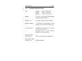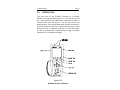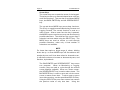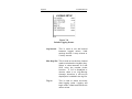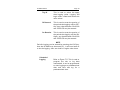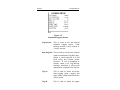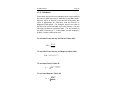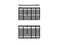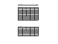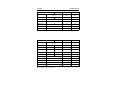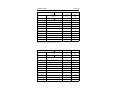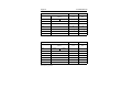
1
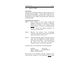
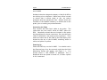
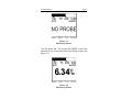
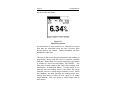
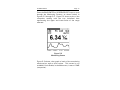
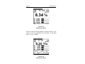
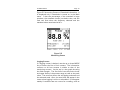
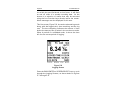
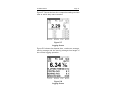
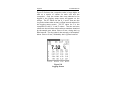
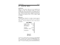
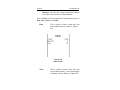
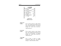
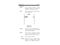
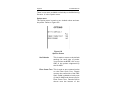
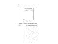
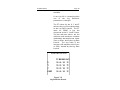
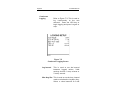
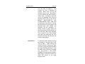
HI-4460
Graphical Readout
User’s Manual
Copyright © 1998-2001 by Holaday Industries, Inc.
Manual #600079
11/01
$25.00
This page is intentionally blank
Revision Record
Manual #600079
HI-4460 Graphical Readout
Revision
--A
B
C
D
Description
Release
Added Upload / Download
Added Battery Operation
Corrected Percent of Standards
Revised Upload Menu
Date
2/98
1/00
9/00
7/01
11/01
This page is intentionally blank
TABLE OF CONTENTS
1.0
QUICK START . . . . . . . . .
Introduction . . . . . . . . . . .
Unpacking and Acceptance
Connecting the Cable . . . .
Powering Up . . . . . . . . . .
Initial Settings . . . . . . . . .
The Screens . . . . . . . . . .
Troubleshooting . . . . . . . .
2.0
SPECIFICATIONS . . . . . . . . . . . . . . . . . . . . 7
3.0
ORIENTATION . . . . . . . . . . . . . . . . . . . . . . 9
4.0
OPERATION - KEYPAD
Introduction . . . . . . . .
Keypad . . . . . . . . . . .
Function Keys . . . .
Log Key . . . . . . . .
Screen Keys . . . . .
Specialized Keys . .
Number Picker . . .
.
.
.
.
.
.
.
.
.
.
.
.
.
.
.
.
.
.
.
.
.
.
.
.
.
.
.
.
.
.
.
.
.
.
.
.
.
.
.
.
.
.
.
.
.
.
.
.
.
.
.
.
.
.
.
.
.
.
.
.
.
.
.
.
.
.
.
.
.
.
.
.
.
.
.
.
.
.
.
.
.
.
.
.
.
.
.
.
.
.
.
.
.
.
.
.
.
.
.
.
.
.
.
.
.
.
.
.
.
.
.
.
.
.
.
.
.
.
.
.
11
11
11
11
11
12
13
14
5.0
OPERATION - SCREENS
Introduction . . . . . . . . .
Monitoring Screens . . . .
Logging Screens . . . . . .
.
.
.
.
.
.
.
.
.
.
.
.
.
.
.
.
.
.
.
.
.
.
.
.
.
.
.
.
.
.
.
.
.
.
.
.
.
.
.
.
.
.
.
.
.
.
.
.
.
.
.
.
.
.
.
.
15
15
15
19
6.0
OPERATION - MENUS
Introduction . . . . . . .
Main . . . . . . . . . . . .
Config . . . . . . . . . . .
Status . . . . . . . . . . .
Option . . . . . . . . . .
.
.
.
.
.
.
.
.
.
.
.
.
.
.
.
.
.
.
.
.
.
.
.
.
.
.
.
.
.
.
.
.
.
.
.
.
.
.
.
.
.
.
.
.
.
.
.
.
.
.
.
.
.
.
.
.
.
.
.
.
.
.
.
.
.
.
.
.
.
.
.
.
.
.
.
.
.
.
.
.
.
.
.
.
23
23
23
25
32
34
.
.
.
.
.
.
.
.
.
.
.
.
.
.
.
.
.
.
.
.
.
.
.
.
.
.
.
.
.
.
.
.
.
.
.
.
.
.
.
.
.
.
.
.
.
.
.
.
.
.
.
.
.
.
.
.
.
.
.
.
.
.
.
.
.
.
.
.
.
.
.
.
.
.
.
.
.
.
.
.
.
.
.
.
.
.
.
.
.
.
.
.
.
.
.
.
.
.
.
.
.
.
.
.
.
.
.
.
.
.
.
.
.
.
.
.
1
1
1
2
2
4
4
5
7.0
LOGGING . . . . . . . . . .
Introduction . . . . . . . . .
Setup Menu . . . . . . . . .
Single Point Logging
Continuous Logging .
Periodic Logging . . .
Scheduled Logging .
Review Menu . . . . . . . .
Upld Menu . . . . . . . . . .
Clear Menu . . . . . . . . .
.
.
.
.
.
.
.
.
.
.
.
.
.
.
.
.
.
.
.
.
.
.
.
.
.
.
.
.
.
.
.
.
.
.
.
.
.
.
.
.
.
.
.
.
.
.
.
.
.
.
.
.
.
.
.
.
.
.
.
.
.
.
.
.
.
.
.
.
.
.
.
.
.
.
.
.
.
.
.
.
.
.
.
.
.
.
.
.
.
.
.
.
.
.
.
.
.
.
.
.
.
.
.
.
.
.
.
.
.
.
.
.
.
.
.
.
.
.
.
.
.
.
.
.
.
.
.
.
.
.
.
.
.
.
.
.
.
.
.
.
37
37
37
37
40
41
43
46
48
50
8.0
USING UPLOAD . . . . .
Introduction . . . . . . . .
Installing the Software
Starting the Software .
Uploading Data . . . . .
Viewing Data . . . . . . .
.
.
.
.
.
.
.
.
.
.
.
.
.
.
.
.
.
.
.
.
.
.
.
.
.
.
.
.
.
.
.
.
.
.
.
.
.
.
.
.
.
.
.
.
.
.
.
.
.
.
.
.
.
.
.
.
.
.
.
.
.
.
.
.
.
.
.
.
.
.
.
.
.
.
.
.
.
.
.
.
.
.
.
.
.
.
.
.
.
.
53
53
53
53
54
55
9.0
USING DOWNLOAD . .
Introduction . . . . . . . .
Installing the Software
Starting the Software .
Downloading the File .
.
.
.
.
.
.
.
.
.
.
.
.
.
.
.
.
.
.
.
.
.
.
.
.
.
.
.
.
.
.
.
.
.
.
.
.
.
.
.
.
.
.
.
.
.
.
.
.
.
.
.
.
.
.
.
.
.
.
.
.
.
.
.
.
.
.
.
.
.
.
.
.
.
.
.
57
57
57
57
57
10.0
INFORMATION . . . . .
Introduction . . . . . . .
General Information .
Startup . . . . . . .
Charging . . . . . .
Battery Operation
Battery Calibration
Reset . . . . . . . . .
Year 2000 . . . . .
Setup . . . . . . . .
.
.
.
.
.
.
.
.
.
.
.
.
.
.
.
.
.
.
.
.
.
.
.
.
.
.
.
.
.
.
.
.
.
.
.
.
.
.
.
.
.
.
.
.
.
.
.
.
.
.
.
.
.
.
.
.
.
.
.
.
.
.
.
.
.
.
.
.
.
.
.
.
.
.
.
.
.
.
.
.
.
.
.
.
.
.
.
.
.
.
.
.
.
.
.
.
.
.
.
.
.
.
.
.
.
.
.
.
.
.
.
.
.
.
.
.
.
.
.
.
.
.
.
.
.
.
.
.
.
.
.
.
.
.
.
.
.
.
.
.
.
.
.
.
.
.
.
.
.
.
59
59
59
59
59
59
61
61
61
61
11.0
STANDARDS . . . . . . . . . . . . . . . . . . . . . . 63
.
.
.
.
.
.
.
.
.
.
Limited Warranty
Holaday Industries, Inc. warrants each model HIn4460 Graphical
Readout to be free from defects in material and workmanship for
a period of one year from the date of shipment to the purchaser.
This warranty extends to the original purchaser only, and does
not apply to the batteries or to any products or parts subject to
misuse, neglect, accident, unauthorized service or abnormal
conditions of operation.
In the event an instrument covered by this warranty fails,
Holaday Industries, Inc. will, without charge, repair and
recalibrate the instrument if returned to their factory within one
year of the original purchase—provided that Holaday Industries'
examination discloses, to its satisfaction, that the product is
defective. Holaday Industries, Inc. may, at its option, replace the
product in lieu of repair. If the defect was caused by misuse,
neglect, accident, unauthorized service or abnormal conditions of
operation, repairs will be billed at a nominal cost. In such cases,
an estimate will be provided before work is started, if requested
by the purchaser.
For warranty service, contact Holaday Industries, Inc. Provide
the serial number of the instrument and complete details
regarding the failure mode. You will then be given either service
information or shipping instructions. Return the instrument to the
factory, transportation prepaid. Repairs will be made at the
factory and the instrument will be returned to you, transportation
prepaid. Holaday Industries, Inc., assumes no responsibility for
loss of, or damage to, products in transit.
Warning!
EXTREME CAUTION IS ADVISED WHEN WORKING IN ENVIRONMENTS
WHERE HIGH-INTENSITY ELECTROMAGNETIC FIELDS MAY EXIST AND
WHERE CONTACT WITH HIGH VOLTAGE OR HIGH CURRENT CIRCUITS
OR APPARATUS IS POSSIBLE. ACCIDENTAL CONTACT WITH OBJECTS
OR CIRCUITS OPERATING AT HIGH VOLTAGES OR HIGH CURRENTS
CAN BE LETHAL! HOLADAY INDUSTRIES, INC. ASSUMES NO LIABILITY
FOR ANY DAMAGES OR PERSONAL INJURY WHICH MAY RESULT
FROM ACCIDENTS ARISING FROM THE USE OF THIS EQUIPMENT.
This page is intentionally blank
HI-4460 Manual
1.0
Page 1
QUICK START
Introduction
This section is intended to help you start using your new
HI-4460 System Readout. You will need a few things to
get started: the HI-4460, the Fiber Optic Cable that was
shipped with your HI-4460, and a probe that is supported
by the HI-4460.
Unpacking and Acceptance
Step 1.
Upon delivery of your order, inspect the
shipping container(s) for evidence of damage.
Record any damage on the delivery receipt
before signing. In case of concealed damage
or loss, retain the packing materials for
inspection by the carrier.
Step 2.
Remove the product from its shipping
containers. Save the boxes and any protective
packing materials for future use.
Step 3.
Check all materials against the packing list to
verify that the equipment received matches
that which was ordered. If any discrepancies
are found, note them and call Holaday
Customer Service for further instructions.
Included with your HI-4460 are the following items:
HI-4460
Carry Case
Battery Charger
HI-4460 Manual
Battery Charger Manual
Be sure that you are satisfied with the contents of your
order and the condition of your equipment before using
Page 2
HI-4460 Manual
the HI-4460.
Holaday Industries charges the battery of the HIn4460 at
the factory prior to shipment. While every effort is made
to ensure that it arrives ready to use, we cannot
guarantee that this will be the case. Always check the
condition of the HI-4460's battery, as well as that of the
probe, prior to making any measurements.
Connecting the Cable
First connect the Fiber Optic cable to the probe. The
cable ends are color-coded—white for XMIT, yellow for
RCV. Identically-colored dots are located on the probe
housing adjacent to these connectors. Be sure that each
cable is attached to the proper probe connector. Then
attach the other end of the cable to the Fiber Optic ports
located at the top of the HI-4460, matching white to
white and yellow to yellow.
Powering Up
Press the PWR key on the HI-4460. You should notice
the Start-up Logo for a few seconds, and then the initial
Monitoring Screen will appear, see Figure 1-1. You
should notice if “NO PROBE” is displayed. This is
displayed when the probe is turned off, or when a probe
is not connected.
HI-4460 Manual
Page 3
Figure 1-1
Monitoring Screen
Turn the probe ON. The words “NO PROBE” have been
replaced by the Composite Field Level being sensed, see
Figure 1-2.
Figure 1-2
Monitoring Screen
Page 4
HI-4460 Manual
Initial Settings
The HI-4460 is shipped in it’s default condition. In this
state, it will start up on the screen shown above with
most of its features turned off or not enabled. Keep in
mind that the HI-4460 may be set up without a probe
attached. The default probe is an HI-4422, so if you
want to setup for a different probe, you must select the
proper one in the Main Menu. Also in the Main Menu,
XYZ is selected for axis. This allows data for each axis to
be displayed on the screen or in a Log File. The power
management functions, Back Light and Screen Saver are
all turned off. They can be turned on in the Config Menu.
By default, logging is set to Single point. When the LOG
key is pressed, the X, Y, and Z values are logged, as well
as the composite.
NOTE
Only certain Holaday probes read from the X, Y, and Z
axes. Refer to your probe’s instruction manual to
determine if your probe reads all three axes.
The Screens
The HI-4460 has two types of screens, Monitoring
screens and Logging screens. The HI-4460 powers up to
the first of four or five Monitoring screens (the fifth
screen does not display until a Standard is selected in the
Main menu). Press the BACK/ENTER or SCREEN/SELECT
keys to cycle through these Monitoring Screens. At the
bottom of the display there are five menu selections
available. Press one of the four function keys just below
the display to access the menu above it. Press the up or
down MODE keys to toggle between the Logging and
Monitoring Screens.
Press the BACK/ENTER or
SCREEN/SELECT keys to cycle through the four Logging
Screens. In addition, eight menu selections are available
HI-4460 Manual
Page 5
on the Logging Screens.
Troubleshooting
If the HI-4460 fails to turn on, the battery may be
depleted. Connect the HI-4460 to the battery charger.
The charger jack is located on the right side of the unit.
If the display will not show a field level, but continues to
display “NO PROBE,” ensure the Fiber Optic cable is
connected correctly (see “Connecting the Cable”). All
connectors and leads should be color coded. If not,
connect the XMIT on the probe to the RECEIVE on the HI4460 and the RCV on the probe to the TRANSMIT on the
HI-4460. If this does not fix the problem, make sure the
probe is turned on. If you still get no change, check that
the probe’s battery is fully charged.
Page 6
HI-4460 Manual
This page is intentionally blank
HI-4460 Manual
2.0
Page 7
HI-4460 SPECIFICATIONS
Size:
Length:
Width:
Weight:
9.05 in (230 mm)
3.70 in. (94 mm)
1.58 lbs. (0.72 kg)
Battery:
7.2 VDC, 1400 mA-h rechargeable
Nickel-Cadmium (NiCd)
Battery Life:
15 hours continuous (full charge)
Battery Charger:
115/230 VAC, approximately 1 hour
Charger Jack: 2.5 mm Phone Jack
Environmental:
Operating Temperature:10 °C to 40
°C (50 °F to 104 °F)
Humidity: 5% to 95% relative
humidity, non-condensing
Standard Fiber
Optic Cable:
200:m, graded index, multimode
Fiber Optic Cable
Connectors:
Standard FSMA
Page 8
HI-4460 Manual
This page is intentionally blank
HI-4460 Manual
3.0
Page 9
ORIENTATION
The front face of the HI-4460 consists of a viewing
display and a keypad (see Figure 3-1). On top of the unit
are connections for the fiber optic cable that is used to
communicate with the probe. On the left side is an
earphone jack. On the right side there are two connectors.
The one toward the top is for communicating with a serial
device such as a computer, and the one near the center
is used to recharge the internal battery using a Holaday
Industries six cell battery charger.
Figure 3-1
HI-4460 Graphical Readout
Page 10
HI-4460 Manual
This page is intentionally blank
HI-4460 Manual
4.0
Page 11
OPERATION - KEYPAD
Introduction
The HI-4460 is comprised of two basic user areas: the
viewing display and the keypad. The display area is
comprised of a backlit LCD and the keypad consists of
four different sets of keys. This chapter describes the
keypad and its functions. The display and different
screens are outlined in the next chapter.
NOTE
For additional information, please refer to the menu tree
in the back of this manual.
Keypad
The HI-4460 uses a rubber keypad that has a total of 13
keys on it. These keys can be broken up into several
different groups of keys: the Function keys, the Log key,
Screen keys, and Specialized keys.
Function Keys
The four function keys are located just below the
viewing display and are used to select sub-menus
displayed at the bottom of each screen. They will also
be used for setting specific numeric levels desired.
Refer to the Number Picker section.
Log Key
Below the four Function keys is the log key. This is
used to toggle the logging function on and off. The
default logging function is single point logging (logging
turns off after one reading is taken). Other logging
functions are explained in the Logging chapter.
Page 12
HI-4460 Manual
Screen Keys
The screen keys are toward the center of the keypad.
These keys make up a diamond shaped area with four
multi function keys. They are the up and down MODE
keys, the BACK/ ENTER key and the SCREEN/SELECT
key.
The up and down MODE keys serve three functions.
The first is to toggle between Monitoring Screens and
Logging Screens. The second function is used on a
menu screen. After a menu function key is pressed,
the MODE keys are used to move up and down among
possible selections. The third function occurs after a
selection has been made using the SELECT key. The
MODE keys are used as arrows to scroll through
possible selections, when only a fixed number of
selections are available.
NOTE
For items that require a larger range of values, holding
down the up or down MODE keys will first advance the
number by one until it has been raised or lowered to ten.
It will then continue to increase or decrease by tens, and
likewise, by hundreds.
The BACK/ENTER and SCREEN/SELECT keys serve
two purposes. When on Monitoring or Logging
screens, they are used to cycle through the several
screen displays available. When on a menu screen,
the SCREEN/SELECT key is used to select items. The
BACK/ENTER key is used to save and exit the menu
screen or menu screen item. To exit a menu or menu
item without saving, use the specialized ESC/CLR key.
Using the ESC/CLR key on a menu screen item returns
the previous value to only that item. Using the
HI-4460 Manual
Page 13
ESC/CLR key to exit the entire menu screen returns
the previous value(s) to all of that menu screen’s
items.
Specialized keys
The four keys at the bottom of the HI-4460 are also
used for specific functions.
RANGE -
This key is used to cycle through
possible measurement ranges,
based on the present UNITS value,
offered by the various probes. It
will cycle through all of the possible
manual ranges and the auto range.
UNITS -
This key is used to cycle through
the possible units of measurement,
based on the present RANGE value,
offered by the various probes.
ESC/CLR -
This key is used to clear graphical
screen information or to escape
from menu selections.
CLR -
Pressing CLR clears the PEAK and
X, Y, and Z data on the graphic
screens, as well as the averaging
buffers.
ESC -
Pressing ESC backs up one level in
the menus without saving any
changes. On menu screens, it
moves back one field.
PWR -
This key is used to turn the unit on
Page 14
HI-4460 Manual
or off. It is also used to turn the
back light OFF (if not set to OFF in
the Config menu).
To turn the unit on, press the PWR key quickly.
To turn the unit off, press and HOLD the PWR key.
To turn the backlight OFF, press the PWR key
quickly. Pressing any other key will turn the
backlight ON again. Holding the PWR key for too
long will turn the unit off.
Number Picker
An option available on some menu selections is the
Number Picker function. When an item associated
with the number picker is selected, the value is
highlighted and the bottom bar on the screen displays
a row of numbers, 0-9. Press the down MODE key to
move the curser to the bottom of the screen. Then,
press the middle two function keys to move among
the numbers. When the curser is on the desired
number, press the ENTER key to select the number.
Continue selecting numbers until the desired value is
shown in the field. Each menu selection that utilizes
the Number Picker function has a predetermined
number of decimal places. When the number being
entered reaches this limit, the curser will move back
up to the menu item. If the number entered is not
valid, it will be set to a minimum or maximum
acceptable number. To move the curser back up to
the menu item before it reaches its limit, press the up
MODE key. When the field contains a decimal point,
its place is also predetermined and the number must
be entered accordingly.
HI-4460 Manual
5.0
Page 15
OPERATION - SCREENS
Introduction
When the HI-4460 is first turned on, the screen displays
the Holaday Industries logo for a few seconds. In addition
to the logo, information on how to contact Holaday is
given, as well as the model number and software version
number of the HI-4460. After this initial screen, a user
screen is displayed. The screen that was active when the
unit was last turned off is displayed. The following
sections explain the different Monitoring and Logging
screens and provide samples of the screens.
NOTE
For additional information, please refer to the menu tree
in the back of this manual.
Monitoring Screens
The first screen you will see is a Monitoring screen. At
the very top of the screen is a bar graph showing field
strength (See Figure 5-1). A thin vertical line shows the
peak value. If the bar graph appears blank, the value is
less than the lower range value. If the bar is completely
filled in, the value is greater than the upper range value.
Change to a different Range to view the reading. Below
the graph is a line of text that shows selected range
limits. The lower limit is on the left, the upper limit is on
the right, and the peak value is in the center. Under that
is another line of text that shows the axes that are being
recorded and the selected range. The axes are shown on
the left side of the screen and the selected range is
shown on the right. Note: An HI-6005 probe has only
one range. The scale readings are for the displayed bar
graph only. A scheduled log period will display the word
LOG in the center of this line. If the unit is logging data,
Page 16
HI-4460 Manual
the word LOG will flash.
Figure 5-1
Monitoring Screen
At the bottom of most screens is a selection of menus
that may be executed using the four Function keys
directly below the screen. Alarm messages are also
displayed in this area.
The rest of the screen shows the present field reading in
large digits, along with the units of measure currently
selected. When there is no probe attached or the probe
is turned off, this area will display “NO PROBE”. The
following screens replace this large digit reading with
information, as described below. If Auto Range is not
selected and the reading doesn’t fall within the range
selected, an over or under range condition occurs. When
this happens, the area showing the reading alerts you,
stating that there is either an over range or an under
range reading. The over range or under range value is
also shown.
HI-4460 Manual
Page 17
Press the BACK/ENTER or SCREEN/SELECT keys to cycle
through the Monitoring Screens, as shown below in
Figures 5-2 through 5-5. Figure 5-2 shows a plot of the
composite reading with the two horizontal bars
representing the upper and lower limits of the range
selected.
Figure 5-2
Monitoring Screen
Figure 5-3 shows a bar graph of each of the axes being
monitored as well as their values. This screen is not
available if Axis Enable, in the Main menu, is set to COMP
(composite).
Page 18
HI-4460 Manual
Figure 5-3
Monitoring Screen
Figure 5-4 shows the bar graphs as well as the plot. This
screen is also not available if Axis Enable, in the Main
menu, is set to COMP.
Figure 5-4
Monitoring Screen
HI-4460 Manual
Page 19
Figure 5-5 shows the Percent of Standard information. It
is displayed only if Standards is turned on in the Main
menu. It has the percentage of the standard in large
numbers, the standard chosen just below that, and the
final two lines show the frequency selected and the
standard value associated with it.
Figure 5-5
Monitoring Screen
Logging Screens
If a logging screen is desired, use the up or down MODE
key to select the first of four screens. The information
common to all four screens is similar to that of the
monitoring screens. At the top is a bar graph showing
the field strength. The first line of text shows the lower
and upper limits of the present range as well as the peak
value. The next line shows the axis being monitored and
the selected scale. Also, the word LOG will appear in the
center when logging is active or scheduled. It will appear
steady if conditions are not correct for a reading, such as
Page 20
HI-4460 Manual
not within the specified levels or time frame. It will flash
on and off when it is actually recording data. At the
bottom is a selection of menus that may be executed
using the four Function keys directly below the screen.
Alarm messages are also displayed in this area.
This first screen, Figure 5-6, shows the selected log mode
along with the logged time, time remaining and the log
rate. The time remaining indicates the amount of time
before the memory fills up when in the continuous mode.
When in periodic or scheduled mode, it shows the time
left for the current period of logging.
Figure 5-6
Logging Screen
Press the BACK/ENTER or SCREEN/SELECT keys to cycle
through the Logging Screens, as shown below in Figures
5-7 through 5-9.
HI-4460 Manual
Page 21
Figure 5-7 shows the last four composite readings and the
time at which they were recorded.
Figure 5-7
Logging Screen
Figure 5-8 shows the elapsed time, continuous average,
moving average and the moving average time length of
the current logging operation.
Figure 5-8
Logging Screen
Page 22
HI-4460 Manual
Figure 5-9 shows the composite value in large digits as
well as a matrix of values for each axis and the
composite. Only the values that were selected to be
logged in the logging setup menu will appear on the
screen. The PT values for the X, Y and Z axes are the
Log Point values taken at the Log Rate interval selected in
the logging setup screen. The PT value for C is the
composite of the X, Y and Z values. The min and max
values are the minimum and maximum numbers obtained
by the sample rate, either 2/sec or 6/sec, during the Log
Rate interval. The avg value is the average of all samples,
either 2/sec or 6/sec, divided by the Log Rate interval.
Figure 5-9
Logging Screen
HI-4460 Manual
6.0
Page 23
OPERATION - MENUS
Introduction
Menus are the areas where you can customize the
settings to meet your particular needs. The menus
available are found at the bottom of the display and can
be accessed by pressing the function keys directly below
them. There are three menus available from both the
monitoring and logging screens. They are main, config
and status.
Main menu
The Main menu, Figure 6-1, is used to view the type of
probe attached to the unit (or select one if no probe is
attached), choose the display rate, and to select the axis
to monitor.
Figure 6-1
Main Menu
To move up or down the list, press the up or down MODE
keys. To select an item, press the SCREEN/SELECT key.
To change the values, press the up or down MODE keys
again. To save the setting, press the BACK/ENTER key.
Page 24
HI-4460 Manual
To back out without changing the item, press the
ESC/CLR key. The new settings are saved when the
menu is exited. To exit the menu and save all new
settings, press the BACK/ENTER key. To exit the menu
and cancel all setting changes, press the ESC/CLR key.
Probe Type
This is used to display the name of the
probe currently attached to the unit. If
there is no probe attached, one may be
selected for setup purposes.
Note: When using an HI-4433-GRE or
HI-4453 the unit will enter a probe
select menu. Select the correct probe
attached.
Display Rate This is used to select the screen display
rate, from 1 to 6 updates per second.
Axis Enable
This is used to select which information
to include on the screen and in the Log
file.
When XYZ is selected,
instantaneous values for each of the
axes is displayed and/or logged. When
COMP is selected, only the composite
of the axes is displayed and/or logged..
Standards
This is used to select which standard to
compare the reading to. Section 11 lists
the standards available.
Frequency
Units
This is displayed only when a standard
comparison is selected. It is used to
select frequency range to be used.
HI-4460 Manual
Page 25
Possible frequency ranges are, kHz,
MHz and GHz. Some standards do not
have frequencies associated with them,
but use other values. Those values,
such as daily, are displayed here.
Frequency
This is used to enter the numerical part
of the frequency desired. When the
standard comparison chosen doesn’t
have any frequency information
associated with it, this field will not be
displayed. If a frequency which is not
within the probes specification is
entered, the closest acceptable value
will be entered upon exiting the number
picker function.
Config menu
The Config menu, Figure 6-2, is used to adjust or set the
HI-4460's operating settings.
Figure 6-2
Config Menu
Page 26
Contrast
Backlight
Time
HI-4460 Manual
This is used to adjust the screen
contrast.
This is used to set the amount of time
before the back light turns off. When
no key is pressed for the specified
amount of time, the backlight will turn
off. The backlight will turn on again
when any key is pressed.
Screen Saver This is used to set the amount of time
before the HI-4460 switches to a low
power mode. When no activity has
taken place for the specified time, the
LCD turns off. The LCD will turn on
again when any key is pressed.
Pass Thru
This is used to “pass” data from the
probe, through the HI-4460 and out the
Serial Port to a computer using
appropriate software, such as
ProbeView.
When a probe is
connected, select YES for Pass Thru, in
the Config menu, then press the
BACK/ENTER key twice and the Pass
Thru screen appears. It will appear
blank until you request information
through your software. A number value
will be displayed. Refer to Figure 6-3.
HI-4460 Manual
Page 27
Figure 6-3
Pass Thru Screen
This screen monitors the values from
the probe as they are transferred to the
computer. To stop Pass Thru, select
Exit.
Temp Units
Download
Code
This is used to select the temperature
units of measurement. Valid choices are
FARH for Fahrenheit and CELS for
Celsius.
This is used to download new HI-4460
system software via personal computer.
You have the option of using either the
RS-232 port or the Fiber Optic port.
You must select Yes to the warning
message that appears below this field
to begin the download. Refer to Section
9 - Using Download Software.
Page 28
HI-4460 Manual
Warning: All data and setup information will be
lost when new software is downloaded.
Also available from the config menu are the sub-menus of
date, time, alarm, and audio.
Date
This is used to enter a date into the
non-volatile memory. Refer to Figure
6-4.
Figure 6-4
Date Screen
Time
This is used to enter a time into the
non-volatile memory. The time displays
in military format. Refer to Figure 6-5.
HI-4460 Manual
Page 29
Figure 6-5
Time Screen
Alarm
This is used to select alarms to be
monitored. Alarms are displayed in the
Alarm field in the Monitoring or Logging
screens. All alarms default to No,
which means they are disabled. When
turned ON by selecting YES, enter
desired values on the second line. Refer
to Figure 6-6.
Page 30
HI-4460 Manual
Figure 6-6
Alarms Screen
High Level
Enable
Low Level
Enable
Temp High
Enable
This is used to select an upper Alarm
level. Any reading above this level will
cause a High Level Alarm. The default
settings are: 10.00 (V/m & kV2/m2),
.0000 (mW/cm2)
This is used to select a lower Alarm
level. Any reading below this level will
cause a Low Level Alarm. The default
settings are: 10.00 (V/m & kV2/m2),
.0000 (mW/cm2)
This is used to select an upper
temperature Alarm level. The default
setting is: 100/ Fahrenheit (38/C)
HI-4460 Manual
Temp Low
Enable
Audio
Page 31
This is used to select a lower
temperature Alarm level. The default
setting is: 100/ Fahrenheit (38/C)
This is used to set the speaker options.
Refer to Figure 6-7.
Figure 6-7
Audio Screen
Volume
Use the up and down MODE keys to
select a volume level. A tone is emitted
as the volume is adjusted.
Enable
This is used to configure the audio
option. The five choices are: None,
Intensity, Cadence, Alarm, and Log
None
No audio options selected.
Intensity Select this to emit a continuous beep
relative to the field strength. When
enabled, the Cadence Enable is
Page 32
HI-4460 Manual
unavailable.
Cadence Select this to emit periodic beeps while
a probe is attached. When enabled, the
Intensity Enable is unavailable.
Alarm
The Alarm setting generates periodic
tones when an alarm condition exists.
LOG
Select this to emit a beep each time the
LOG key is pressed while in single point
logging, or periodically while logging
with any other logging setup.
Status menu
The Stat menu is used to view the battery, temperature
and memory information. Refer to Figure 6-8.
Figure 6-8
Status Screen
HI-4460 Manual
Page 33
HI-4460 Battery
This line displays the percentage of
charge left in the HI-4460 battery.
When the value is highlighted, see
the battery charger manual to
calibrate the battery.
Probe Battery
This line displays the current
voltage level of the probe battery.
It is blank when there is no probe
attached or the probe is turned off.
Probe Temp
This line displays the current
temperature level of the probe. It is
blank when there is no probe
attached or the probe is turned off.
HI-4460 Temp
This line displays the current
temperature value of the HI-4460.
Storage Used
This line displays the amount of
memory used for data logging.
Storage Unused
This line displays the amount of
memory still available for data
logging.
Percent Used
This line displays the percentage of
memory used.
Sample Rate
This line displays the number of
samples taken per second. If XYZ
is selected, 2/sec will be displayed.
If COMP is selected,6/sec will be
displayed.
Page 34
HI-4460 Manual
There is one menu available exclusively to the Monitoring
Screens. It is the Option menu.
Option menu
The Option menu is used to set default values and zero
the probe. Refer to Figure 6-9.
Figure 6-9
Options Screen
Set Defaults
This is used to return to the default
settings for each type of probe.
Your choices are NONE, ALL or any
ONE of the probes supported by
the HI-4460.
Fiber Comm Test This is used to test communication
on the Fiber Optic Port. Simply
connect the same side of the Fiber
Optic Cable included to both ports
on the HI-4460 and choose yes for
Fiber Comm Test. Results will be
shown near the bottom of the
HI-4460 Manual
Page 35
screen.
Zero Probe
This appears only when a probe is
attached. It is used to zero the
probe. Care must be taken to only
zero the probe when the probe is in
a zero field.
Page 36
HI-4460 Manual
This page is intentionally blank
HI-4460 Manual
7.0
Page 37
LOGGING
Introduction
The logging feature is used to gather the readings from
the probe and save the for later review. Each set of
logged data contains a Log File Header. This header
includes the setup information for a particular set of data.
A new log file is created anytime the setup is changed.
Since a change in the setup is required for each set of
Scheduled data, a new log file is created each time it is
used. For Single Point and Periodic logging, the data is
appended to the end of the log file. When using
Continuous logging, a new log file is created every time
logging is stopped, and started again.
There are four menus available exclusively to the logging
screens. They are setup, review, upld and clear.
Setup menu
The Setup menu is used to select parameters for logging
operations. There are four possible logging operations.
Single Point, Continuous, Periodic and Scheduled. The
sub-menu log is available to choose the items you want
to be included in the log file.
Log Mode
Single Point
Logging
This is used to select between
Single Point, Continuous, Periodic
and Scheduled logging.
Refer to Figure 7-1. This is used to
log a single point when the LOG
key is pressed. No further setup is
needed except to choose what to
include in the log file by pressing
Page 38
HI-4460 Manual
the LOG menu at the bottom.
Figure 7-1
Single Point Logging Screen
Available to the setup menu is the log sub-menu.
Log
The log definition menu, Figure 72, is used to select which
information to include in the log
file. This menu is also available as
a read-only screen from the upld,
review and clear menus by
pressing the Detail, then Log
menus on those screens. When
the Axis Enable on the Main Menu
is set to XYZ, any of the 16 values
shown below can be selected to be
shown on the screen, as well as be
included in the log file. If the Axis
Enable is set to COMP, then only
the four values for COMP will be
HI-4460 Manual
Page 39
available.
A new log file is created anytime
one of the Log Definition
parameters is changed.
The PT values for the X, Y and Z
axes are the Log Point values taken
at the Log Rate interval. The PT
value for COMP is just the
composite of the X, Y and Z value.
The min and max values are the
minimum and maximum numbers
obtained by the sample rate, either
2/sec or 6/sec, during the Log Rate
interval. The avg value is the
average of all samples, either 2/sec
or 6/sec, divided by the Log Rate
interval.
Figure 7-2
Log Definition Screen
Page 40
HI-4460 Manual
Continuous
Logging
Refer to Figure 7-3. This is used to
log continuously at the rate
selected. Press the LOG key to
begin logging and press it again to
stop.
Figure 7-3
Continuous Logging Screen
Log Interval
This is used to set the interval
between logged values. Valid
settings include 1 every minute to
2 every second.
Mov Avg Size This is used to set the time interval
used to calculate the Log Mov Avg.
Select a value between 0.0 and
HI-4460 Manual
Page 41
99.9 using the number picker
function. If 0.0 is displayed or
chosen, there is no Log Moving
Average, therefore, it will not be
displayed or included in the Log
File.
Trig Lo
This is used to select the lower
data logging value. Logging will
begin when a field level below this
values exists.
Trig Hi
This is used to select the upper
data logging value. Logging will
begin when a field level above this
value exists.
Note
The Setup values for Log Interval, Mov Avg Size, Trig Lo
and Trig Hi do not change when the logging function is
changed. If new values are desired, they must be
changed.
Periodic
Logging
Refer to Figure 7-4. This is used to
program the HI-4460 to log for a
fixed amount of time at a
predetermined interval.
For
example, you can log for the first
10 seconds at the start of every
minute.
Page 42
HI-4460 Manual
Figure 7-4
Periodic Logging Screen
Log Interval
This is used to set the interval
between logged values. Valid
settings include 1 every minute to
2 every second.
Mov Avg Size This is used to set the time interval
used to calculate the Log Mov Avg.
Select a value between 0.0 and
99.9 using the number picker
function. If 0.0 is displayed or
chosen, there is no Log Moving
Average, therefore, it will not be
displayed or included in the log file.
Trig Lo
This is used to select the lower
data logging value. Logging will
begin when a field level below this
values exists.
HI-4460 Manual
Page 43
Trig Hi
This is used to select the upper
data logging value. Logging will
begin when a field level above this
value exists.
Off Interval
This is used to enter the portion of
the period that logging will be OFF.
Any time value between 00:00:00
and 23:59:59 may be entered.
On Duration
This is used to enter the portion of
the period that logging will be ON.
Again, any time between 00:00:00
and 23:59:59 may be entered.
NOTE
Periodic logging can be started by pressing the LOG key,
then the HI-4460 may be turned off. It will turn itself on
to do the logging, then turn itself off again when done.
Scheduled
Logging
Refer to Figure 7-5. This is used to
program the unit to log data
unattended. It can be programmed
to start logging at a predetermined
date and time and log for a
predetermined time.
Page 44
HI-4460 Manual
Figure 7-5
Scheduled Logging Screen
Log Interval
This is used to set the interval
between logged values. Valid
settings include 1 every minute to
2 every second.
Mov Avg Size This is used to set the time interval
used to calculate the Log Mov Avg.
Select a value between 0.0 and
99.9 using the number picker
function. If 0.0 is displayed or
chosen, there is no Log Moving
Average, therefore, it will not be
displayed or included in the log file.
Trig Lo
This is used to select the lower
data logging value. Logging will
begin when a field level below this
values exists.
Trig Hi
This is used to select the upper
HI-4460 Manual
Page 45
data logging value. Logging will
begin when a field level above this
value exists.
Start Time
This is used to enter the time to
start logging. Any time between
00:00:00 and 23:59:59 may be
entered.
Start Date
This is used to enter the date to
start logging.
Any valid date
format may be entered.
Duration
This is used to enter the length of
time to log. Any time between
00:00:00 and 23:59:59 may be
entered.
NOTE
In order for scheduled logging to begin, the LOG key must
be pressed before or during the time of the intended
recording. The HI-4460 may be turned off after the LOG
key is pressed, and it will turn itself on at the time entered
for start time.
Log Moving
Average
The Log Moving Average is
computed using the Log Interval
and the Moving Average Size
values. A Log Moving Average
buffer is dynamically set up to hold
the number of logged values that
can be taken in the Moving
Average Size time.
Page 46
HI-4460 Manual
Example
Log Interval:
Mov Avg Size:
1 per second
6 minutes
Then the Moving Average will be
the average of the last 360 logged
values, if they exist.
If there
haven’t been 360 logged values,
then zeros will be inserted as place
holders and used to calculate the
average. When the 361st value is
taken, it will replace the first, and
so on.
Review menu
The Review menu is used to view data in a log file. Refer
to Figure 7-6.
Figure 7-6
Review Data Screen
File to View
This is used to select the log file to
be viewed. The File to View field
HI-4460 Manual
Page 47
displays the first seven log files, if
they exist. The first file is selected
by default. To view it, select
either the Data or Graph menu.
Use the up and down MODE keys
to select a different log file to
review.
Detail
This is used to view log file
information. This is a read only
view of information selected in the
Setup menu. The Log sub-menu in
the Detail sub-menu is used to
view information on what data is
being logged.
Data
Press Data to review the file in
numerical mode. The numerical
review shows a screen similar to
the Log Setup Screen. Only logged
values are shown. Use menu keys
corresponding to the arrows at the
bottom of the screen to move
through the log file data.
Graph
Press Graph to review the file in
graphical mode. You can review
up to three variables graphically.
Only values that have been logged
are available. Use the up and
down MODE, and BACK/ENTER
and SCREEN/SELECT keys to
choose the item to be viewed for
each graph. Use the menu keys
corresponding to the arrows at the
Page 48
HI-4460 Manual
bottom of the screen to move
through the log file data.
NOTE
Use the arrows in the menu area and the corresponding
function keys below to move through data. The single
arrows move one data point at a time. Double arrows
scroll to the opposite end of the data, or to the next full
screen of data.
UPLD Menu
The Upload menu is used to upload log file information to
a computer or other device, Figure 7-7. Refer to section
8.0 for Using Upload Software.
Figure 7-7
Upload Data Screen
Start Header
This header displays the newest
two log files in memory. The
newest log file is selected by
default.
End Header
This header displays the newest
HI-4460 Manual
Page 49
two log files in memory. The
newest log file is selected by
default. More than one log file
may be sent at once. By default,
only the newest log file in memory
will be sent. If a block of the files
are to be uploaded, they must be
selected using the up and down
MODE,
BACK/ENTER
and
SCREEN/SELECT keys. Files must
be selected by the block, so all log
files between the Start Header file
selected and End Header file
selected will be uploaded. To
define a block of files, select the
end file from the block desired; the
file with the oldest date desired.
Then, return to the Start Header
and select the beginning file from
the block desired; the file with the
newest date desired.
Upload Port
To send the data selected, choose
the method of transfer: None, RS232 or Fiber. After having the
Upload Software running on your
computer, press the BACK/ENTER
key and uploading will begin. If the
HI-4460 cannot find the computer
you will receive a NO HOST
CONNECTED message and a beep.
Wait about 5 seconds and the HI4460 will return to the main
logging menu.
Page 50
HI-4460 Manual
None
Sends nothing.
RS-232
Sends the selected files using the
RS-232 port on the side of the HI4460.
Fiber
Sends the selected files using the
Fiber Optic port on top of the HI4460. An HI-4413P Fiber Optic
Modem is required. When
connecting the fiber optic cable,
you must switch the polarity of
one of the ends, white to yellow
and yellow to white.
Exit
Once uploading has begun, you
can abort the upload by pressing
the EXIT sub-menu button.
Clear menu
The Clear menu is used to clear data log files, Figure 7-8.
Figure 7-8
Clear Data Screen
HI-4460 Manual
Page 51
Start Header
This header displays the newest
two log files in memory. The
newest log file is selected by
default.
End Header
This header displays the newest
two log files in memory. The
newest log file is selected by
default. More than one log file
may be cleared at once.
By
default, only the newest log file in
memory will be cleared. If a block
of the files are to be cleared, they
must be selected using the up and
down MODE, BACK/ENTER and
SCREEN/SELECT keys. Files must
be selected by the block, so all log
files between the Start Header file
selected and End Header file
selected will be cleared. To define
a block of files, select the end file
from the block desired; the file
with the oldest date desired. Then,
return to the Start Header and
select the beginning file from the
block desired; the file with the
newest date desired.
Clear Data
To clear the data selected, move to
the Clear Data field and press the
SCREEN/SELECT key. Then use
the up and down MODE keys to
select YES. Press BACK/ENTER
twice and the data selected will be
Page 52
HI-4460 Manual
cleared.
HI-4460 Manual
Page 53
This page is intentionally blank
Page 54
8.0
HI-4460 Manual
Using Upload Software
Introduction
Log File data can be uploaded to a personal computer
using either the Fiber Optic port or RS-232 port. If you
plan to use the Fiber Optic port, you will need an HI4413P Fiber Optic modem. When connecting the fiber
optic cable, you must switch the polarity of one of the
ends, white to yellow and yellow to white. If using the
RS-232 port, connect the RS-232 cable between the HI4460 and the computer. Before starting the upload
process, you will need to install the Holaday upload
program onto your computer.
Installing the Software
Your Holaday upload program is provided on 3.5" floppy
or CD ROM disks. After closing any open applications,
insert disk 1 into your floppy drive. Click Start and Run.
Select the file A:\Setup.exe and click Open. Follow the
menus to complete the installation of the software.
Starting the Software
Click Start, Programs, and HIupload. The HI-4460 Upload
Utility splash screen will display for a few seconds. Select
the Default Com Port you will be connecting to. The
program is now running with the Incoming Data tab
highlighted. Verify that the proper communication settings
are selected. These should be the default settings.
Baud
Parity
Data Bits
Stop Bit
9600
None
8
1
You are now ready to upload your log file data to your
HI-4460 Manual
Page 55
computer.
Uploading Data
Connect the HI-4460 to your computer, using either the
fiber optic port or the RS-232 port. Start the Holaday
upload program on your computer.
On the HI-4460, go to the upload menu.
Start Header
This header displays the newest
two log files in memory. The
newest log file is selected by
default.
End Header
This header displays the newest
two log files in memory. The
newest log file is selected by
default. More than one log file
may be sent at once. By default,
only the newest log file in memory
will be sent. If a block of the files
are to be uploaded, they must be
selected using the up and down
MODE,
BACK/ENTER
and
SCREEN/SELECT keys. Files must
be selected by the block, so all log
files between the Start Header file
selected and End Header file
selected will be uploaded. To
define a block of files, select the
end file from the block desired; the
file with the oldest date desired.
Then, return to the Start Header
and select the beginning file from
the block desired; the file with the
Page 56
HI-4460 Manual
newest date desired.
Upload Port
To send the data selected, choose
the method of transfer: None, RS232 or Fiber. After having the
Upload Software running on your
computer, press the BACK/ENTER
key and uploading will begin. The
files selected will upload to your
computer and the headers for each
file will display in the Incoming
Data window. If the HI-4460
cannot find the computer you will
receive a NO HOST CONNECTED
message and a beep. Wait about 5
seconds and the HI-4460 will
return to the main logging menu.
Recheck your connections and
settings.
Viewing Data
To view the data, highlight one of the file headers in the
Incoming Data window. Next, click on the VIEW button.
The data will be loaded into the Data window. The data
can be viewed in the upload program, or can be saved as
an Excel spreadsheet file by clicking on the File menu, and
Save As. Choose a file name and location for the file on
your computer and click Save.
HI-4460 Manual
Page 57
This page is intentionally blank
Page 58
9.0
HI-4460 Manual
Using Download Software
Introduction
Occasionally the need may arise for updating the software
in an HI-4460. Updated revisions of software can be
downloaded from your computer into an HI-4460 through
either the Fiber Optic port or RS-232 port using the
Holaday download program. If you plan to use the Fiber
Optic port, you will need an HI-4413P Fiber Optic modem.
When connecting the fiber optic cable, you must switch
the polarity of one of the ends, white to yellow and
yellow to white. If using the RS-232 port, connect the
RS-232 cable between the HI-4460 and the computer.
Before starting the download process, you will need to
install the Holaday download program onto your
computer.
Installing the Software
Your Holaday download program is provided on 3.5"
floppy or CD ROM disks. After closing any open
applications, insert disk 1 into your floppy drive. Click
Start and Run. Select the file A:\Setup.exe and click
Open. Follow the menus to complete the installation of
the software.
Starting the Software
Click Start, Programs, and HIdownload. The HI-4460
Download Utility splash screen will display for a few
seconds. The program is now running. Click the Browse
button, locate the file which will be downloaded and click
Open.
Downloading the File
In the HI-4460 Config menu, use the up and down MODE,
BACK/ENTER and SCREEN/SELECT keys, to select
HI-4460 Manual
Page 59
DOWNLOAD CODE. Select either RS232 or Fiber.
WARNING!
Before downloading new software into the HI-4460, make
sure the battery is completely charged.
WARNING!
Before downloading new software into the HI-4460, make
sure you have all logged data uploaded to your computer.
All logged data in the HI-4460 will be lost!
When you are ready to download the new software, move
down to ARE YOU SURE and change it to YES. Pressing
the BACK/ENTER key establishes communications with
your computer and displays the message
... DOWNLOADING ...
At this point, pressing the ESC key will cancel the
download operation.
In the Download Utility software, select the correct
communication port. The button toggles between ports 1
and 2. The Progress area should display the message
Device Found. You are now ready to download the new
software. Click the Download button and the program will
begin downloading the new software to the HI-4460.
Again, as soon as the Download button is clicked, all data
in the HI-4460 is lost. The download process will take a
few minutes to complete. If you want to stop the
download process, you can either click the Abort button
in the software or press the ESC key on the HI-4460.
Aborting the download process will leave the old revision
of software in the HI-4460 running as before, but all data
will be lost.
Page 60
HI-4460 Manual
Upon completion, the HI-4460 will reset and power up
using the new software.
HI-4460 Manual
Page 61
10.0 Information
Introduction
This section contains information about several different
features of the HI-4460.
General Information
Startup
When the HI-4460 is turned on, the screen flickers for
about 1-2 seconds. If a menu key is pressed before
this, the menu will be exited and the screen will
reappear after the flicker.
Charging
The HI-4460 utilizes a Gas Gauge microchip to
determine its battery life. The charger has a discharge
button that works along with the Gas Gauge to
discharge the battery to a reference level and then
charge it to it’s maximum. This allows the HI-4460 to
keep track of how much charge is left.
Battery Operation
Do not disconnect the battery pack from the HI-4460
Graphical Display. Disconnecting the battery will
interfere with the calibration of the battery charge
status indicator and will cause a battery fault
indication.
If the battery is disconnected, it will be necessary to
recalibrate the Battery Charge Status Indicator. To do
this, turn off the HI-4460, connect the battery charger
(charger connected to the 120/240 VAC mains power
supply), and press the discharge button on the
charger. This will discharge and recharge the battery
and will properly initialize the Battery Charge Status
Page 62
HI-4460 Manual
Indicator.
When fully charged, the HI-4460 Battery Graphical
Display may indicate a charge level of 97 to 105%.
This is normal and this fully charged level may begin
to drop as the battery ages.
When the battery is being charged (with the HI-4460
turned off) power is still being drawn from the battery
to maintain the system monitoring features of the HI4460. This current being drawn from the battery may
cause the battery charger to prematurely indicate a
fully charged unit. To continue to charge the battery
to its full capacity, disconnect the battery charger
from the HI-4460 for approximately 15 seconds and
then reconnect. The battery charging sequence will
continue to fully charge the battery. Reinitiating the
charge sequence in this manner will not adversely
affect the ultimate life of the battery.
While charging the battery, if the HI-4460 is turned
on, the battery charger may prematurely indicate a
fully charged unit. To continue to charge the battery
to its full capacity, disconnect the battery charger
from the HI-4460 for approximately 15 seconds and
then reconnect. The battery charging sequence will
continue to fully charge the battery. . Reinitiating the
charge sequence in this manner will not adversely
affect the ultimate life of the battery
Should the battery become overly discharged (no
display for example), it may be necessary for the
charger to trickle charge the battery to a level where
it is safe to begin the fast-charge sequence. This may
take several hours if the battery is severely over
HI-4460 Manual
Page 63
discharged. During this time, the battery charger will
indicate PENDING. When a sufficient charge level is
reached, the charger will automatically shift to the
fast-charge mode.
Because the HI-4460 Graphical Display is monitoring
its operation even when OFF, there is a load on the
battery. This load along with the self-discharge
characteristic of a NiCad battery will deplete the
charge of the battery even when OFF. A typical
battery life in the OFF condition is typically 12-13
days. After this time, the battery must be recharged.
It is possible to leave the HI-4460 connected to the
battery charger indefinitely with no effect on the
ultimate life of the battery.
Battery Calibration
When the HI-4460 Battery level is highlighted, the
battery must be calibrated. See the Battery Charger
Manual. Sometimes, the battery will not be calibrated
after cycling. Cycle it again to calibrate the battery.
Reset
There is a reset button installed on the circuit board
inside the HI-4460. It can be accessed through a hole
on the upper right hand side of the battery pack cover,
on the back of the unit. The memory is backed up by
battery, therefore all data and setup information will
remain intact.
Year 2000
The HI-4460 is Year 2000 Compliant.
Setup
The HI-4460 can be setup for a particular probe even
Page 64
HI-4460 Manual
though it is not attached. Turn the HI-4460 on and
the words NO PROBE will be displayed on the screen.
The first step is to choose which probe you want to
setup for. Go to the Main screen and choose a probe
in the Probe Type field. Now set any setting the way
you want, even logging setup can be done. When
ready, attach the probe and everything will already be
set up.
HI-4460 Manual
Page 65
11.0 Standards
Listed here are the various standards that are programed
into the HI-4460 and can be selected in the Main menu.
Where a value, or formula, is not shown in the table, the
value is dependant on frequency and the Electric or
Magnetic Field values. For example, there is no value in
the first row or the first table for Power density. Use the
following formulas to calculate them. For any formula in
the table containing a “f” in the tables, use the frequency
in MHz, unless noted otherwise.
To calculate Power Density for Electric Fields (Pde)
Pde =
E*E
3770
To calculate Power Density for Magnetic Fields (Pdh)
Pdh = H * H * 37 .7
To calculate Electric Fields (E)
E =
Pde * 3770
To calculate Magnetic Fields (H)
H =
Pdh
37 . 7
Page 66
HI-4460 Manual
ACGIH (controlled)
Power Density
(mW/cm2)
E-Field
E-Field
(V/m)
H-Field
(A/m)
614
163
H-Field
30kHz-100kHz
100kHz-3MHz
614
16.3/f
3MHz-30MHz
1842/f
16.3/f
61.4
16.3/f
61.4
0.163
E-Field
(V/m)
H-Field
(A/m)
30MHz-100MHz
100MHz-300MHz
1
300MHz-3GHz
f/300
3GHz-15GHz
10
15GHz-300GHz
10
Note: American Conference of Governmental Industrial Hygienists
IEEE C95.1 (controlled)
Power Density
(mW/cm2)
E-Field
H-Field
3kHz-100kHz
100
1,000,000
614
163
100kHz-3MHz
100
10,000/f^2
614
16.3/f
3MHz-30MHz
900/f^2
10,000/f^2
1842/f
16.3/f
1
10,000/f^2
61.4
16.3/f
61.4
0.163
30MHz-100MHz
100MHz-300MHz
300MHz-3GHz
1
f/300
3GHz-15GHz
10
15GHz-300GHz
10
HI-4460 Manual
Page 67
IEEE C95 (uncontrolled)
Power Density
(mW/cm2)
3kHz-100kHz
100kHz-1.34MHz
E-Field
H-Field
100
1,000,000
E-Field
(V/m)
H-Field
(A/m)
614
163
100
10,000/f^2
614
16.3/f
1.34MHZ-3MHz
180/f^2
10,000/f^2
823.8/f
16.3/f
3MHz-30MHz
180/f^2
10,000/f^2
823.8/f
16.3/f
0.2
940,000/f^3.336
27.5
158.3/f^1.668
27.5
0.0729
E-Field
(V/m)
H-Field
(A/m)
30MHz-100MHz
100MHz-300MHz
0.2
300MHZ-3GHz
f/1500
3GHz-15GHz
f/1500
15GHz-300GHz
10
FCC (US) (controlled)
Power Density
(mW/cm2)
E-Field
H-Field
300kHz-3MHz
100
614
1.63
3MHz-30MHz
900/f^2
1842/f
4.89/f
30MHZ-300MHz
1
61.4
0.163
300MHz-1.5GHz
f/300
1.5GHz-100GHz
5
Page 68
HI-4460 Manual
FCC (US) (uncontrolled)
Power Density
(mW/cm2)
E-Field
E-Field
(V/m)
H-Field
(A/m)
H-Field
300kHz-1.34MHz
100
614
1.63
1.34MHz-30MHz
180/f^2
824/f
2.19/f
30MHZ-300MHz
0.2
27.5
0.073
300MHz-1.5GHz
f/1500
1.5GHz-100GHz
1
E-Field
(V/m)
H-Field
(A/m)
NRPB (British)
Power Density
(mW/cm2)
E-Field
H-Field
< 24Hz
24Hz-600Hz
600HZ-600kHz
600kHz-12MHz
25,000
160,000
600/f (kHz)
64,000/f (Hz)
1000
64
600/f (MHz)
18/f^2 (MHz)
12MHz-200MHz
0.66
50
0.13
200MHz-400MHz
16.5*f^2
250*f
0.66*f
400MHz-800MHz
2.6
100
0.26
800MHz-1.55GHz
4.1*f^2
125*f
0.33*f
1.55GHz-300GHz
10
194
0.52
Note: For NRPB, use frequency in GHz for “f”.
HI-4460 Manual
Page 69
ICNIRP (Occupational)
Power Density
(mW/cm2)
E-Field
E-Field
(V/m)
H-Field
(A/m)
H-Field
0-1Hz
—
—
1.63 x 10⁵
1Hz-8Hz
—
20,000
1.63 x 10⁵/f
8Hz-25Hz
—
20,000
2 x 10⁴/f
0.025kHz-0.82kHz
—
500/f
20/f
0.82kHz-65kHz
—
610
24.4
0.065MHz-1MHz
—
610
1.6/f
1MHz-10MHz
—
610/f
1.6/f
10MHz-400MHz
1
61
0.16
400MHz-2000MHz
f/400
2GHz-300GHz
3f
5
1/2
0.008f1/2
137
0.36
E-Field
(V/m)
H-Field
(A/m)
Note: Frequency (f) in same units as defined in 1st column.
ICNIRP (General Public)
Power Density
(mW/cm2)
E-Field
H-Field
0-1Hz
—
—
3.2 x 10⁴
1Hz-8Hz
—
10,000
3.2 x 10⁴/f
8Hz-25Hz
—
10,000
4,000/f
0.025kHz-0.8kHz
—
250/f
4/f
0.8kHz-3kHz
—
250/f
5
3kHz-150kHz
—
87
5
0.15MHz-1MHz
—
87
0.73/f
1MHz-10MHz
—
87/f1/2
0.73/f
10MHz-400MHz
400MHz-2000MHz
2GHz-300GHz
0.2
28
0.073
f/2000
1.375f1/2
0.0037f1/2
1
61
0.16
Note: Frequency (f) in same units as defined in 1st column.
Page 70
HI-4460 Manual
Safety Code 6 (Canada) Exposed Workers
Power Density
(mW/cm2)
(MHz)
E-Field
E-Field
(V/m)
H-Field
(A/m)
H-Field
0.003-1
—
600
4.9
1-10
—
600/f
4.9/f
10-30
—
60
4.9/f
30-300
1
60
0.163
f/300
3.54f1/2
0.0094f1/2
5
137
0.364
E-Field
(V/m)
H-Field
(A/m)
—
280
2.19
1-10
—
280/f
2.19/f
10-30
—
28
2.19/f
300-1500
1500-40,000
Note: Frequency (f) in MHz.
Safety Code 6 (Canada) General Public
Power Density
(mW/cm2)
(MHz)
0.003-1
30-300
300-1500
1500-40,000
Note: Frequency (f) in MHz.
E-Field
H-Field
0.2
28
0.073
f/1500
1.585f1/2
0.0042f1/2
1
61.4
0.163
HI-4460 Manual
Page 71
-- NOTES --
Page 72
HI-4460 Manual
-- NOTES --
Page 74
HI-4460 Manual