1
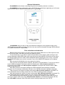
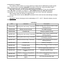
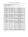
CQ-64GSMrf guard control device
v.1.1
User manual
2011
General information
CQ-64GSMrf device allows controlling the guard, who patrols perimeter or territory.
CQ-64GSMrf device is designed to work with RF-ID tags and allows registering up to 64 route
tags to monitor up to 4 different routes and up to 16 guard tags.
CQ-64GSMrf device is able to form and transmit messages to two registered users using
GPRS-channel and SMS-messages. The first user can receive information through GPRS-channel
or by SMS, the second - only by SMS.
First activation and indication
Before turning on the device you have to buy and activate SIM-card, turn PIN request on and
set it's PIN as "0000". After that you can insert SIM into device.
To turn the device on you have to press the right button on the device. After turning on and
during initialization GSM LED blinks green once per second and MODE LED blinks red two times
per second. When device is ready to work GSM LED starts to blink green once every 3 seconds
and MODE LED blinks once every 6 seconds. Color of the MODE LED depends on the battery
charge.
After successful initialization you can program the device:
First you have to program phone numbers, that device will send SMS to. To do so you have to
send an SMS messages to the device with the following text: <ID>,91<phone number> to
program the first number and <ID>,92<phone number> to program the second number. <ID> unique 4-digit device ID.
After that you have to program settings for GPRS activation and connecting to WinSC
program. List of necessary commands is shown in the “GPRS-connection settings” paragraph.
Than you have to set device working mode using <ID>,93*<mode number> command. For
more information about working modes see in the “Device working modes” paragraph.
After that program the amount of patrol routes using <ID>,93#<route amount> command. For
more information about working modes see in the “Patrol routes programming” paragraph.
After programming route amount you have to program RF-ID tags for every route. To do so
you have to select each route using <ID>,93R<route number> command and program RF-IDs
with <ID>,99RP command. More information about working modes see in the “RF-ID
programming" paragraph.
If the device will be used by 2 or more guards you might want to additionally program guard
tags. It can be done by sending <ID>,99RS command to the device. More information about
working modes see in the “Guard RF-ID programming” paragraph.
After that, if needed, you can activate and configure the calendar. To turn the calendar on
send <ID>,93С+ command, to configure it - <ID>,93СRххххххх and <ID>,93С*ххххххх
commands. For more information about working modes see in the “Calendar” paragraph.
After all that is done the devise is ready to work.
To turn off the device send a <ID>,OFF command. Device will send an acknowledge message
and turn off.
Attention!: battery charging must be made only at +5°С - +40°С. Otherwise battery may be
damaged.
Indication
LED
Indication
Description
READ/GSM
Blinks green once every 3 seconds
GSM coverage OK. Device turned on and
working properly.
READ/GSM
Blinks once per second
No GSM coverage
READ/GSM
Constant red
Ready to read RF-ID tag
MODE/PWR
Blinks green once every 6 seconds
High battery level. Device turned on and
working properly.
MODE/PWR
Blinks yellow once every 6 seconds
Medium battery level. Device turned on
and working properly.
MODE/PWR
Blinks red once every 6 seconds
Low battery level. Device turned on and
working properly.
MODE/PWR
Constant red
Battery is charging
MODE/PWR
Constant green
Battery is fully charged. Charger is plugged
in
MODE/PWR
Constant yellow
RF-ID programming mode is on
MODE/PWR
Red for 1 second + short sound
signal
Failed to read RF-ID tag.
MODE/PWR
Red for 1 second + long sound
signal
Error while reading RF-ID tag or tag not
registered.
MODE/PWR
Green for 1 second + triple sound
signal
RF-ID tag successfully read
RF-ID tag reading and sending panic message
To read a RF-ID tag you have to press any of two buttons and put upper part of the device
near the tag (1-2 centimeters). When the button is pressed READ/GSM LED will turn red and you
have 5 seconds to read the tag.
If the tag is successfully read than MODE/PWR LED will turn green for one second and triple
sound signal will occur.
If device failed to read the tag, MODE/PWR LED will turn red for one second and short sound
signal will occur. In that case repeat the operation.
To send a panic message you have to simultaneously press both buttons and hold them for
one second.
GPRS-connection settings
In order for the device to connect to the WinSC program and send information using GPRS
channel you have to set the following parameters:
GPRS mode activation – set by a <ID>,89Gx command, where <ID> - unique 4-digit device
ID and х can be either "+" (the first user receives information via GPRS) or ”-“ (the first user
receives information via SMS).
IP-address – set by the <ID>,89Iхх command, where <ID> - unique 4-digit device ID and хх –
IP-address of the computer with installed WinSC program.
APN - set by the <ID>,89Aхх command, where <ID> - unique 4-digit device ID and хх –
access point name (32 symbols maximum).
TCP port – set by the <ID>,89Pхх command, where <ID> - unique 4-digit device ID and хх –
TCP port number (5 digits maximum).
Login for GPRS access (if used by mobile operator) – set by the <ID>,89Y1хх command,
where <ID> - unique 4-digit device ID and хх - login (8 symbols maximum).
Password for GPRS access (if used by mobile operator) – set by the <ID>,89Y2хх command,
where <ID> - unique 4-digit device ID and хх - password (8 symbols maximum).
Number of attempts to connect to the software – set by the <ID>,89Rхх command, where
<ID> - unique 4-digit device ID and хх – number of attempts (from 1 to 255).
Time between reconnect attempts – set by the <ID>,89Mхх command, where <ID> - unique
4-digit device ID and хх – time between reconnect attempts in minutes (from 1 to 255).
DNS-server IP-address (if used) – set by the <ID>,89DIхх command, where <ID> - unique 4digit device ID and хх - IP-address.
Domain name (if used) – set by the <ID>,89DDхх command, where <ID> - unique 4-digit
device ID and хх – domain name 32 symbols maximum).
Device working modes
Device has four working modes.
Mode one:
Route point control.
In this mode device sends a message every time a registered RF-ID tag is read. Message
contains device account, guard tag number and route tag number.
If no guard tags are registered it’s number in the message will be 00.
To activate this mode you have to send the <ID>,93*1 command to the device.
Mode two:
Strict route control.
In this mode device analyses the route and sends a message only if the route has been
violated.
Device analyses order of RF-ID readings and time interval between the readings. In case if
readings is made in the wrong order or time interval between readings is exceeded a message is
sent.
To activate this mode you have to send the <ID>,93*2 command to the device.
Mode three:
The third mode is a compilation of the first two modes. Device sends messages in both cases
when the tag is read and when the route is violated.
To activate this mode you have to send the <ID>,93*3 command to the device.
Mode four:
The fourth mode allows setting time, when to start patrolling, duration of the patrol, time
interval between patrols and number of patrols per day.
The fourth mode parameters are set using <ID>,98Taaaa,bbbb,cccc,d command, where
<ID> - unique 4-digit device ID, aaaa – time, when to start the first patrolling, bbbb – patrolling
duration, cccc – time between patrolling, d – number of patrolling (if 0 – not counted).
In this mode, when the patrolling time comes, the device will turn on the sound signal. In 5
minute time the guard must start the patrolling and read the first tag. If that‘s not done, the device
will form and send an alarm message. During the time, programmed in the device, guard must
read all the programmed RF-ID tags. After each reading device forms a message that contains
device account, guard tag number and route tag number. Order of readings and time between
them are not analyzed. If the guard didn’t read all programmed tags in time device forms a
message, where the quantity of the missed tags are shown.
Attention: to function correctly, the device must have date and time set in it. To set the date
and time you have to send any SMS message to the device. If the device was turned off or the
battery was fully discharged the date and time will be lost and you will have to send the message
again.
Attention: Patrolling duration must be at least 10 minutes shorter that time between
patrolling.
To activate this mode you have to send the <ID>,93*4 command to the device.
RF-ID tag registration
Guard tag programming.
There are three modes to program a tag:
1. RF-ID tag programming. This mode is activated by the <ID>,99RS command, where <ID> unique 4-digit device ID. When this command is received MODE LED will turn yellow and
all previously registered tags are deleted from the memory. After the LED turned yellow you
have 30 seconds to read an RF-ID tag in order to register it. After registering the tag the
countdown starts from the beginning. If in 30 seconds time no tag was read - CQ-64GSMrf
leaves programming mode.
2. RF-ID tag adding. This mode is activated by the <ID>,99RSA command, where <ID> unique 4-digit device ID. When this command is received MODE LED will turn yellow. After
the LED turned yellow you have 30 seconds to read an RF-ID tag in order to register it.
Registered tag will be added to the end of the list without deleting previously programmed
tags. After registering the tag the countdown starts from the beginning. If in 30 seconds
time no tag was read - CQ-64GSMrf leaves programming mode.
3. RF-ID tag replacing. This mode is activated by the <ID>,99RSRxx command, where <ID> unique 4-digit device ID and хх – number of the tag you want of replace. When this
command is received MODE LED will turn yellow. After the LED turned yellow you have 30
seconds to read an RF-ID tag in order to register it. This tag will de saved as the number
given in the command. In case there are no registered tag with this number an error
message will be formed. After registering the tag the countdown starts from the beginning.
If in 30 seconds time no tag was read - CQ-64GSMrf leaves programming mode.
In case you are trying to register already registered key, MODE LED will turn red for one second
and you will hear a long sound signal.
Route tag programming.
Route tags are programmed only for the route activated at the moment.
There are three modes to program a tag:
4. RF-ID tag programming. This mode is activated by the <ID>,99RP command, where <ID> unique 4-digit device ID. When this command is received MODE LED will turn yellow and
all previously registered tags are deleted from the memory. After the LED turned yellow you
have 30 seconds to read an RF-ID tag in order to register it. After registering the tag the
countdown starts from the beginning. If in 30 seconds time no tag was read - CQ-64GSMrf
leaves programming mode.
5. RF-ID tag adding. This mode is activated by the <ID>,99RPA command, where <ID> unique 4-digit device ID. When this command is received MODE LED will turn yellow. After
the LED turned yellow you have 30 seconds to read an RF-ID tag in order to register it.
Registered tag will be added to the end of the list without deleting previously programmed
tags. After registering the tag the countdown starts from the beginning. If in 30 seconds
time no tag was read - CQ-64GSMrf leaves programming mode.
6. RF-ID tag replacing. This mode is activated by the <ID>,99RPRxx command, where <ID> unique 4-digit device ID and хх – number of the tag you want of replace. When this
command is received MODE LED will turn yellow. After the LED turned yellow you have 30
seconds to read an RF-ID tag in order to register it. This tag will de saved as the number
given in the command. In case there are no registered tag with this number an error
message will be formed. After registering the tag the countdown starts from the beginning.
If in 30 seconds time no tag was read - CQ-64GSMrf leaves programming mode.
In case you are trying to register already registered key, MODE LED will turn red for one second
and you will hear a long sound signal.
Route programming
CQ-64GSMrf can store up to 4 patrolling routes.
Depending on configuration you can have 1, 2 or 4 active routes. However, overall number of
registered tags is constant - 64. So if you have 1 active route, than maximum number of tags in it
will be 64, if 2 active routes – 32 each, 4 routes – 16 each.
Route programming is made using SMS.
To program the number of the active routes you have to send the <ID>,93#x command, where
<ID> - unique 4-digit device ID and х can take the following values: 1 – one route, 2 – two routes,
3 – four routes.
Attention! When you change the number of the active routes all registered tags are deleted.
To choose a route you have to send the following command: <ID>,93Rx where <ID> - unique
4-digit device ID and х – route number.
To set the time interval for the strict route control (the second mode) you have to send the
<ID>,99Txx.hhmm,yy.hhmm command, where <ID> - unique 4-digit device ID, xx and yy tag
numbers, hhmm – time interval in hours and minutes.
If you have to change the time interval for only one tag than the command may look like this:
<ID>,99Txx.hhmm
Attention! Tag numbers may differ if you use two or more routes:
If you use two routes, than the tag numbers in the first route will be from 01 to 32, and in the
second – from 33 to 64.
If you use four routes, than the tag numbers in the first route will be from 01 to 16, in the
second – from 17 to 32, in the third – from 33 to 48, in the fourth – from 49 to 64.
If you want to set the same interval for all the tags you can use the <ID>,99T00.hhmm
command, where <ID> - unique 4-digit device ID and hhmm - time interval in hours and minutes.
Calendar
Calendar allows automatically switch routes and work modes depending on the day of the
week.
For every day you can set a work mode and a route.
To turn the calendar on send the <ID>,93С+ command, to turn off - <ID>,93С-
To set working mode switch you have to send the following command <ID>,93С*ххххххх
where <ID> - unique 4-digit device ID and ххххххх – seven-digit code. In this code the digit
represents working mode (1 – first mode, 2 – second mode, 3 – third mode, 4 – fourth mode) and
it’s position day of the week (1 – Monday, 2 – Tuesday, etc.).
To set working mode switch you have to send the following command <ID>,93СRххххххх
where <ID> - unique 4-digit device ID and xxxxxxx – seven-digit code. In this code the digit
represents working mode (1 – first route, 2 – second route, 3 – third route, 4 – fourth route) and it’s
position day of the week (1 – Monday, 2 – Tuesday, etc.).
By default for all days of the week are set the 1-st work mode and the 1-st route.
Attention: If the device was turned off or the battery was fully discharged the date and time
will be lost and you will have to send any SMS message to the device in order to reset them.
Settings request
Settings request command is a special command that is designed for using with mobile phone
only. Answer to this command cannot be decoded by WinSC software and must be received on
mobile phone only.
To request settings you have to send the <ID>,S command, where <ID> - unique 4-digit
device ID.
As an answer device will send a message with it’s settings. Message will have the following
form:
<account>,<number of active routes>,<calendar status>,<route settings in
calendar>,<mode settings in calendar>,<activated route>,<activated mode>,<current guard
tag>,<last activated tag>,<battery state>
<account> - Device 4-digit account.
<number of active routes> - May take on three values: #1 – one route, #2 – two routes, #3 –
four routes.
<calendar status> - May take on two values: С+ - calendar activated, С- - turned off.
<route settings in calendar> - displayed as CR<route settings for each day>.
<mode settings in calendar> - displayed as C*<mode settings for each day>.
<activated route> - Shows currently active route. Displayed as R<route number>.
<activated mode> - Shows currently activated working mode. Displayed as *<mode
number>..
<current guard tag> - Displayed as S<guard tag number>. If no guard tags are registered it
will be S00.
<last activated tag> - Displayed as P<tag number>.
<battery state> - Displayed as B<battery state>. This value can change from 99 (maximum)
to 0 (minimum).
Control and programming
To program and control the device you have to send a special SMS message from any mobile
phone. Every message must contain the unique 4-digit device ID.
All messages send to the device must start from the ID, after which a comma must be placed.
Message text must be entered without spaces.
When device receives the message, it analyzes it and in case if command is typed wrong
sends back the "E801000" message. If the command processed successfully, "R801000" message
will be sent. Only exception is the tag programming messages. If the device successfully entered
programming mode – no message is send.
Command list is shown below:
Command
<ID>,91<phone number>
<ID>,91
<ID>,92<phone number>
<ID>,92
<ID>,95<account>
Description
Example
Register the 1-st user number
1111,91+37121234567
Delete the 1-st user number
1111,91
Register the 2-nd user number
1111,92+37121234567
Delete the 2-nd user number
1111,92
Change device account. Default - 1234
1111,954321
Command
Description
Example
<ID>,OFF
Turn off the device
1111,OFF
<ID>,89G+
Enable GPRS
1111,89G+
<ID>,89G-
Disable GPRS
1111,89G-
<ID>,89I<IP-address>
Set IP-address
1111,89I211.21.211.21
Set APN
1111,89Ainternet
Set login for GPRS access
1111,89Y1login
Set password for GPRS access
1111,89Y2password
Set TCP-port
1111,89P925
<ID>,89R<attempts>
Set number of attempts to connect to
software. Maximum 255.
1111,89R2
<ID>,89M<minutes>
Set time interval between connection
attempts. Maximum 255.
1111,89M1
Set DNS-server IP-address
1111,89DI211.21.211.21
<ID>,89DD<domain name>
Set domain name
1111,89DDdomenname
<ID>,98Taaaa,bbbb,cccc,d
Configure 4-th mode preferences
1111,98T0900,0230,0400,3
Set number of active routes
1111,93#2
<ID>,93*<mode number>
Change active mode
1111,93*1
<ID>,93R<route number>
Change active route
1111,93R3
<ID>,93С+
Turn calendar on
1111,93С+
<ID>,93С-
Turn calendar off
1111,99С-
<ID>,93С*ххххххх
Set modes for each day of the week
1111,93C*1123122
<ID>,93СRххххххх
Set routes for each day of the week
1111,93CR1134211
<ID>,99Txx.hhmm
Set time interval
1111,99Т03.0030
Enter guard tag registration mode
1111,99RS
Enter guard tag adding mode
1111,99RSA
Enter guard tag replacement mode
1111,99RSR01
<ID>,99RP
Enter tag registration mode
1111,99RP
<ID>,99RPA
Enter tag adding mode
1111,99RPA
Enter tag replacement mode
1111,99RPR01
<ID>,89A<APN>
<ID>,89Y1<login>
<ID>,89Y2<password>
<ID>,89P<port>
<ID>,89DI<IP-address>
<ID>,93#<number of
routes>
<ID>,99RS
<ID>,99RSA
<ID>,99RSRxx (where хх –
tag number. 2 symbols
obligatory)
<ID>,99RPRxx (where хх –
tag number. 2 symbols
obligatory)
Device messages in the WinSC software
Depending on the message delivery mode, messages are sent in two different protocols. SMSmessages are sent in Contact ID protocol, GPRS-messages - SIA-IP.
Massages consist of the following elements:
Account - CQ-64GSMrf account
Partition – duty guard number. If no Guard tags are registered than it will be 00.
Event code.
SMS message code GPRS message code
Description
E120000
1120000
Panic button pressed
E302000
1302000
Battery low
R302000
3302000
Battery OK
R308000
3308000
Device is turned on
E308000
1308000
Device is turned off
R7000xx
37000xx
RF-ID tag is activated, where хх – tag
number
R800000
3800000
Duty guard changed
E801000
1801000
Wrong command
R801000
3801000
Command successfully executed
E137000
1137000
Tamper alarm
R137000
3137000
Tamper restore
E705000
1705000
Guard didn’t go patrolling in time
E7060xx
17060xx
Partial patrolling, where хх – amount of
missed tags
E707000
1707000
Date/time lost
R707000
3707000
Date/time restored
E704000
1704000
Multiple pressing of the read button
R7030хх
37030хх
Patrolling started from tag xx, where xx –
tag number
E7010хх
17010хх
Route violation in the xx point, where xx –
tag number
R7010хх
37010хх
Route restored at xx point, where xx – tag
number
E7020хх
17020хх
Time interval exceeded for point xx, where
xx – tag number
E80200x
180200x
Route number set as x, where x – route
number code
E80300x
180300x
Mode x activated, where x – mode number
E80400x
180400x
Route x activated, where x – route number