1
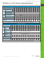
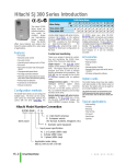
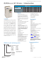
Prices as of April 16, 2014. Check Web site for most current prices.
DURApulse AC Drives – Introduction
DURApulse Drives
Motor Rating
Hp
1
2
3
5 7.5 10 15 20 25 30 40 50 60 75 100
kW
.75 1.5 2.2 3.7 5.5 7.5 11 15 18.5 22 30 37 45 55 75
Single/Three-Phase Input 230V 4 4 4
Three-Phase 230VClass
4 4 4 4 4 4 4 4 4
Three-Phase 460V Class
Features
Overview
The DURApulse series of AC drives offers
all of the features of our GS2 series of
drives including dynamic braking, PID,
removable keypad and RS-485 Modbus
communication. The DURApulse AC
drive also offers sensorless vector control
with the option of encoder feedback
for enhanced speed control. The standard smart keypad (or Human Interface
Module) is designed with defaults for the
North American customer and allows you
to configure the drive, set the speed, start
and stop the drive, and monitor critical
parameters for your application. In addition, this keypad has internal memory
that allows four complete programs to be
stored and transferred to any DURApulse
drive. The DURApulse series offers three
analog inputs, eleven digital inputs, and
one SPDT relay output.
• Simple Volts/Hertz control
• Sensorless vector control with autotune
• Sensorless vector control with optional
encoder feedback card, for better speed
control
• Sinusoidal pulse width modulation (PWM)
• Variable carrier frequency, depending on
model
• IGBT technology
• Starting torque: 125% @ 0.5 Hz/150% @ 1Hz
• 150% rated current for one minute
• Electronic overload protection
• Stall prevention
• Adjustable accel and decel ramps with
linear and S-curve settings
• Automatic torque and slip compensation
• Internal dynamic braking circuit for models under 20 hp; optional baking units
available for models 20 hp and above
• DC braking
• Five skip frequencies
• Trip history
• Programmable jog speed
• Integral PID control
• Removable smart keypad with parameter
upload/download
• Keypad with memory to store up to four
programs of any DURApulse drive
• Eleven programmable digital inputs
• Three programmable analog inputs
• Three digital and one SPDT relay
programmable outputs
• One programmable analog output
DURApulse part numbering system
GS3 - 2 020
Applicable Motor Capacity
1P0: 1HP
3P0: 3HP
7P5: 7.5HP
015: 15HP
025: 25HP
040: 40HP
060: 60HP*
100: 100HP*
Input Voltage
4 4 4 4 4 4 4 4 4 4 4 4 4 4 4
2P0: 2HP
5P0: 5HP
010: 10HP
020: 20HP
030: 30HP
050: 50HP
075: 75HP*
* 60, 75 and 100HP models
available in GS3-4xxx only
• One digital frequency output
• RS-485 Modbus communications
• Ethernet communication optional
• Two-year warranty
• UL/cUL/CE listed
Accessories
• AC line reactors
• EMI filters
• RF filter
• Braking resistors
• B raking units (for models 20 hp and above)
• Fuse kits and replacement fuses
• Replacement cooling fans
• Remote panel adapter
• Replacement keypad
•K
eypad cables in 1, 3, and 5-meter lengths
• Ethernet interface
• F our and eight-port RS-485 multi-drop
termination boards
• KEPDirect I/O or OPC Server
• GSoft drive configuration software
• GS3-FB – feedback card
•G
S-485HD15-CBL – ZIPLink RS485
communication cable for connection to
the DL06 and D2-260 15-pin ports
•U
SB-485M – USB to RS-485 PC adapter
(see “Communications Products”
chapter for detailed information)
Detailed descriptions and specifications for GS
accessories are available in the “GS/DURApulse
Accessories” section.
Typical Applications
• Conveyors
• Fans
• Pumps
• Compressors
• HVAC
•Material handling
• Mixing
• S hop tools
• Extruding
• Grinding
2: 200-240VAC
4: 380-480VAC
Series Name
Book 2 (14.1)
eDR-32
AC Drives
1-800-633-0405
Prices as of April 16, 2014. Check Web site for most current prices.
DURApulse AC Drives Specifications
Company
Information
Drives
230V Class
Model Name: GS3-xxx
Price
21P0
22P0
23P0
25P0
Soft Starters
27P5
2010
2015
2020
2025
2030
2040
2050
$242.00 $293.00 $347.00 $400.00 $549.00 $698.00 $889.00 $1,104.00 $1,298.00 $1,486.00 $2,177.00 $2,637.00
Maximum Motor Output
Output Rated Output Current (A)
Rating
Maximum Output Voltage
Power
Transmission
HP
1.0
2.0
3.0
5.0
7.5
10
15
20
25
30
40
50
kW
.75
1.5
2.2
3.7
5.5
7.5
11
15
18.5
22
30
37
5
7
11
17
25
33
49
65
75
90
120
145
Three-phase 200 to 240V (proportional to input voltage)
Rated Frequency
* Input Rated Voltage/Frequency
Rating
Rated Input Current (A)
Sensors:
Proximity
Three-phase
200/208/220/230/240 VAC, 50/60Hz
11.9 / 5.7 15.3 / 7.6 22 / 15.5
20.6
26
Voltage/Frequency Tolerance
34
50
60
75
90
110
142
Voltage: ± 10% Frequency: ± 5%
Watt Loss @ 100% I (W)
Weight (lb [kg])
60
82
130
194
301
380
660
750
920
1300
1340
1430
4.5
[2.034]
4.5
[2.034]
9.4
[4.24]
9.4
[4.24]
13.3
[6.031]
13.3
[6.031]
14.3
[6.487]
26.5
[12]
26.5
[12]
26.5
[12]
77.2
[35]
77.2
[35]
Model Name: GS3-xxx
41P0 42P0 43P0 45P0 47P5 4010 4015
Price
$323.00 $360.00 $385.00 $427.00 $613.00 $734.00 $957.00 $1,165.00 $1,383.00 $1,570.00 $2,001.00 $2,436.00 $2,788.00 $3,130.00 $3,498.00
Watt Loss @ 100% I (W)
Weight (lb [kg])
4025
4030
4040
4050
4060
4075
4100
1
2
3
5
7.5
10
15
20
25
30
40
50
60
75
100
.75
1.5
2.2
3.7
5.5
7.5
11
15
18.5
22
30
37
45
55
75
2.7
4.2
5.5
8.5
13
18
24
32
38
45
60
73
91
110
150
11.2
14
19
25
32
39
49
60
63
90
130
160
70
102
132
176
250
345
Sensors:
Flow Switches
Process
Relays and
Timers
Voltage: ± 10% Frequency: ± 5%
3.9
4.4
4.1
9.4
13.2
13.5
[1.759] [1.994] [1.857] [4.24] [6.002] [6.106]
Sensors:
Level
Signal
Devices
Three-phase,
380/400/415/440/460/480VAC, 50/60Hz
5.9
Sensors:
Temperature
Stacklights
0.1 to 400 Hz
4.3
Sensors:
Limit Switches
Pushbuttons
and Lights
Three-phase 380 to 480V (proportional to input voltage)
3.2
Sensors:
Encoders
Sensors:
Pressure
460V Class – Three-Phase
Maximum Motor HP
Output
kW
Output Rated Output Current
Rating (A)
Maximum Output
Voltage
Rated Frequency
Rated Voltage/
*Input Frequency
Rating Rated Input Current
(A)
Voltage/Frequency Tolerance
Sensors:
Photoelectric
Sensors:
Current
*A
ll 3-phase power sources must be symmetrical.
Do not connect any DURApulse drives to grounded, center-tapped delta transformers (which are typically used for lighting circuits).
4020
Motion: Servos
and Steppers
Motor Controls
0.1 to 400 Hz
Single/Three-phase
Motors
445
620
788
1290
1420
1680
2020
2910
3840
14.4
[6.525]
26.5
[12]
26.5
[12]
26.5
[12]
77.2
[35]
77.2
[35]
77.2
[35]
116.8
[53]
116.8
[53]
*A
ll 3-phase power sources must be symmetrical.
Do not connect any DURApulse drives to grounded, center-tapped delta transformers (which are typically used for lighting circuits).
Pneumatics:
Air Prep
Pneumatics:
Directional Control
Valves
Pneumatics:
Cylinders
Pneumatics:
Tubing
Pneumatics:
Air Fittings
Appendix
Book 2
Terms and
Conditions
Book 2 (14.1)
www.automationdirect.com/drives
AC Drives
eDR-33
Prices as of April 16, 2014. Check Web site for most current prices.
DURApulse AC Drives General Specifications
General Specifications
Control Characteristics
Control System
Pulse Width Modulation, Carrier frequency adjustable from 1k–15kHz depending on the model.
This system determines the control methods of the AC drive.
00: V/Hz open loop control
01: V/Hz closed loop control
02: Sensorless Vector
03: Sensorless Vector with external feedback
Rated Output Frequency
0.1 to 400.0 Hz
Output Frequency Resolution
0.1 Hz
Overload Capacity
150% of rated current for 1 minute
Torque Characteristics
Includes auto-torque boost, auto-slip compensation, starting torque 125% @ 0.5 Hz / 150% @ 1.0 Hz
Braking Torque
20% without braking resistor, 125% with optional braking resistor (braking circuit built-in only for units under 20 hp)
DC Braking
Operation frequency 60–0 Hz, 0–100% rated current, Start time 0.0–5.0 seconds, Stop time 0.0–25.0 seconds
Acceleration/Deceleration Time
0.1 to 600 seconds (linear or non-linear acceleration/deceleration), second acceleration/deceleration available
Voltage/Frequency Pattern
Settings available for Constant Torque - low & high starting torque, Variable Torque - low & high starting torque, and user
configured
Stall Prevention Level
20 to 200% of rated current
Operation Specifications
Frequency
Setting
Operation
Setting
Inputs
Input
Terminals
Keypad
External
Signal
Keypad
External
Signal
Digital
Sink/Source
Selectable
Analog
Setting by <UP> or <DOWN> buttons
Potentiometer - 3 to 5 kq, 0 to 10 VDC (input impedance 10 kq), -10 to +10 VDC, 4 to 20 mA (input impedance 250q),
0 to 20 mA; Multi-Speed Inputs 1 to 4, RS-232C/RS-485 communication interface
Setting by <RUN>, <STOP>, <JOG> , <FWD>, <REV> buttons
Forward/Stop, Reverse/Stop (run/stop, fwd/rev), 3-wire control, Serial Communication RS-232C & RS-485 (Modbus RTU)
11 user-programmable: FWD/STOP, REV/STOP, RUN/STOP, REV/FWD, RUN momentary (N.O.), STOP momentary (N.C.),
External Fault (N.O./N.C.), External Reset, Multi-Speed Bit (1-4), Manual Keyboard Control, Jog, External Base Block (N.O./
N.C.), Second Accel/Decel Time, Speed Hold, Increase Speed, Decrease Speed, Reset Speed to Zero, PID Disable (N.O.), PID
Disable (N.C.), Input Disable
3 user-configurable, 0 to 10V (input impedance 10 kq),
0 to 20 mA, 4 to 20 mA (input impedance 250q), 10 bit resolution
-10V to +10V, 10 bit resolution
Digital
4 user-programmable: Inverter Running, Inverter Fault, At Speed, Zero Speed, Above Desired Frequency, Below Desired
3 transistors Frequency, At Maximum Speed, Over Torque Detected, Above Desired Current, Below Desired Current, PID Deviation Alarm,
Heatsink Overheat Warning (OH), Soft Braking Signal, Above desired Frequency 2, Below desired Frequency 2, Encoder Loss
1 relay
Output
Terminals Digital Square One digital square wave output representing drive frequency
Wave
1 user-programmable, 0 to 10V, 8 bit resolution frequency, current, process variable PV
Analog
Outputs
Operating Functions
Automatic voltage regulation, voltage/frequency characteristics selection, non-linear acceleration/deceleration, upper and lower
frequency limiters, 15-stage speed operation, adjustable carrier frequency (1 to 15 kHz), PID control, 5 skip frequencies,
analog gain & bias adjustment, jog, electronic thermal relay, automatic torque boost, trip history, software protection
Protective Functions
Electronic Thermal, Overload Relay, Auto Restart after Fault, Momentary Power Loss, Reverse Operation Inhibit, Auto Voltage
Regulation, Over-Voltage Stall Prevention, Auto Adjustable Accel/Decel, Over-Torque Detection Mode, Over-Torque Detection
Level, Over-Torque Detection Time, Over-Current Stall Prevention during Acceleration, Over-Current Stall Prevention during
Operation
Operator Interface
Environment
Operator Devices
9-key, 2 line x 16 character LCD display, 5 status LEDs
Programming
Parameter values for setup and review, fault codes
Status Display
Output Frequency, Motor Speed, Scaled Frequency, Output Current, Motor Load, Output Voltage, DC Bus Voltage, PID
Setpoint, PID Feedback, Frequency Setpoint
Key Functions
RUN, STOP/RESET, FWD/REV, PROGRAM, DISPLAY, <UP>, <DOWN>, ENTER
Enclosure Rating
Protected Chassis, IP20
Ambient Temperature
-10°C to 40°C (14°F to 104°F)
Storage Temperature
-20°C to 60°C (-4°F to 140°F) – during short term transportation period
Ambient Humidity
20 to 90% RH (non-condensing)
Vibration
9.8 m/s2 (1G) less than 10 Hz; 5.9 m/s2 (0.6G) 10 to 60 Hz
Installation Location
Altitude 1000m or lower above sea level, keep from corrosive gas, liquid and dust
Noise filter, input AC reactor, output AC reactor, cable for remote operator, programming software, dynamic braking
resistor, dynamic braking unit; RF filter; remote panel adapter; Ethernet interface; four and eight port RS-485 multi-drop
termination boards, replacement keypads, fuse kits and replacement fuses
Options
Book 2 (14.1)
eDR-34
AC Drives
1-800-633-0405
Prices as of April 16, 2014. Check Web site for most current prices.
DURApulse Drives Specifications – Installation
Understanding the installation requirements for
your DURApulse AC drive will help to ensure
that it operates within its environmental and
electrical limits.
Note: Never use only this catalog for installation instructions
or operation of equipment; refer to the user manual, GS3-M.
Drives
Soft Starters
Environmental Specifications
Protective Structure 1
Motors
IP20
Power
Transmission
Ambient Operating Temperature 2 -10 to 40°C (14°F to 104°F) f
Storage Temperature 3
-20 to 60°C (-4°F to 140°F)
Humidity
To 90% (no condensation)
Vibration 4
9.8 m/s2 (1g), less than 10 Hz
5.9 m/s2 (0.6g),10 to 60 Hz
Motor Controls
Location
Altitude 1,000 m or less, indoors (no corrosive
gases, liquids or dust)
Sensors:
Proximity
Motion: Servos
and Steppers
1: Protective structure is based upon EN60529
2: The ambient temperature must be in the range of
-10° to 40°C. If the range will be up to 50°C, you will need to set the carrier frequency to 2.1 kHz or less and derate the output current to 80% or less.
3: The storage temperature refers to the short-term temperature during transport.
Watt-loss Chart
GS3 Drive Model
At full load
GS3-21P0
GS3-22P0
GS3-23P0
GS3-25P0
GS3-27P5
GS3-2010
GS3-2015
GS3-2020
GS3-2025
GS3-2030
GS3-2040
GS3-2050
GS3-41P0
GS3-42P0
GS3-43P0
GS3-45P0
GS3-47P5
GS3-4010
GS3-4015
GS3-4020
GS3-4025
GS3-4030
GS3-4040
GS3-4050
GS3-4060
GS3-4075
GS3-4100
60
Sensors:
Pressure
194
Sensors:
Temperature
301
380
150mm (6 inches)
660
Sensors:
Level
Air Flow
or more
750
Sensors:
Flow Switches
920
1430
Pushbuttons
and Lights
50mm
(2 inches)
or more
50mm
(2 inches)
or more
Stacklights
Enclosure
70
Signal
Devices
102
132
Process
176
Relays and
Timers
150mm (6 inches)
250
or more
345
Pneumatics:
Air Prep
445
620
Pneumatics:
Directional Control
Valves
788
1290
1420
1680
2020
2910
Sensors:
Encoders
Sensors:
Current
82
1340
Sensors:
Photoelectric
Sensors:
Limit Switches
4: Conforms to the test method specified in JIS CO911 (1984)
130
1300
Company
Information
Pneumatics:
Cylinders
Minimum Clearances and Air Flow
Warning: AC drives generate a large amount of heat which may damage the AC drive.
Auxiliary cooling methods are typically required in order not to exceed maximum ambient
temperatures.
3840
Pneumatics:
Tubing
Pneumatics:
Air Fittings
Appendix
Book 2
Warning: M
aximum ambient temperatures must not exceed 50°C (122°F), or 40°C (104°F)
for models 7.5 hp (5.5 kW) and higher!
Book 2 (14.1)
www.automationdirect.com/drives
AC Drives
eDR-35
Terms and
Conditions
Prices as of April 16, 2014. Check Web site for most current prices.
DURApulse AC Drives Specifications — Terminals
Main Circuit Terminals
Terminal
L1, L2, L3
T1, T2, T3
B1, B2
+2, – (negative)
Description
Input Power
AC Drive Output
Braking Resistor Connection (Under 20HP)
External Dynamic Brake Unit (20HP & Over)
Ground
GS3-4030 shown
Control Circuit Terminals
Terminal Symbol
+24V
DI1
DI2
DI3
DI4
DI5
DI6
DI7
DI8
DI9
DI10
DI11
DCM
+10V
AI1
AI2
AI3
ACM
Description
Remarks
DC Voltage Source
(+24V, 20mA), used only for AC drive digital inputs wired for source mode operation
Digital Input 1
Digital Input 2
Digital Input 3
Digital Input 4
Digital Input 5
Digital Input 6
Digital Input 7
Digital Input 8
Digital Input 9
Input Voltage: Internally Supplied (see Warning below)
Sink Mode: Low active, VinL Min = 0V, VinL Max = 15V,
Iin Min = 2.1mA, Iin Max = 7.0mA
Source Mode: High active, VinH Min = 8.5V, VinH Max = 24V, Iin Min = 2.1mA, Iin Max = 7.0mA
Input response: 12–15 msec
Also see “Basic Wiring Diagram” on the next pages.
Digital Input 10
Digital Input 11
Digital Common
Internal Power Supply
+10VDC (10mA maximum load)
Analog Input
0 to +10 V input only
Analog Input
0 to 20mA / 4 to 20mA input
Analog Input
-10 to +10 V input only
Analog Common
R1O
Relay Output 1 Normally Open
R1C
Relay Output 1 Normally Closed
R1
Relay Output 1 Common
DO1
DO2
DO3
DOC
AO
FO
Photocoupled digital output
Photocoupled digital output
Photocoupled digital output
Resistor Load:
240VAC - 5A (N.O) / 3A (N.C.)
24VDC - 5A (N.O.) / 3A (N.C.)
Inductive Load:
240VAC - 1.5A (N.O) / 0.5A (N.C)
24VDC - 1.5A (N.O) / 0.5A (N.C) See P 3.01 to P 3.03
Maximum 48VDC, 50mA
Digital Output Common
Analog Output
0 to +10 V 2mA Output
Digital Frequency Output
Square wave pulse train output
Warning: Do NOT connect external voltage sources to the digital inputs. Permanent damage may result.
Note: Use twisted-shielded, twisted-pair or shielded-lead wires for the control signal wiring. It is recommended to
run all signal wiring in a separate steel conduit. The shield wire should only be connected at the AC drive. Do
not connect shield wire on both ends.
Book 2 (14.1)
eDR-36
AC Drives
1-800-633-0405
Prices as of April 16, 2014. Check Web site for most current prices.
DURApulse AC Drives – Basic Wiring Diagram
Company
Information
Drives
Power Wiring Diagram - drives under 20 hp
Soft Starters
Note: Users MUST connect wiring according to the circuit diagram shown below. (Refer to user manual GS3-M for additional specific wiring information.)
Motors
Note: Refer to the following pages for explanations and information regarding feedback cards, line reactors, braking resistors, EMI and RF filters, and fuses:
DR-48, DR-50, DR-69, DR-74, DR-80, DR-81.
Power
Transmission
Braking resistor
(optional)
Motion: Servos
and Steppers
BR
Motor Controls
JUMPER
+
Power Source
200-240V+-10%
(50,60Hz+-5%)
380-480V+-10%
(50,60Hz+-5%)
Use any two of L1, L2, L3
for 230V 1-phase models
L1
L2
L3
B1
(–)
Sensors:
Proximity
B2
DURAPULSE
GS3-xxxx
AC Motor
T1
IM
3Ø
T2
Sensors:
Photoelectric
Sensors:
Encoders
Sensors:
Limit Switches
T3
Sensors:
Current
Note: Grounding terminals
are internally connected.
Motor grounding
terminal
Grounding resistance
less than 0.1
Mechanical
Coupling
Sensors:
Pressure
Sensors:
Temperature
Sensors:
Level
A
A
B
B
GS3-FB
(optional)
OC 12V
Factory
Default
OC=open collector
TP=totem pole
Main circuit (power) terminals
VP
A
B
Control circuit terminal
Pushbuttons
and Lights
PG
Stacklights
Signal
Devices
+12V
Process
GND
DCM
TP 5V
Sensors:
Flow Switches
Encoder
Output 12VDC
Shielded leads
Relays and
Timers
Pneumatics:
Air Prep
Pneumatics:
Directional Control
Valves
Pneumatics:
Cylinders
Warning: D
o not plug a modem or telephone into the GS3/DURApulse RJ-12 Serial Comm Port, or permanent damage may result.
Terminals 2 and 5 should not be used as a power source for your communication connection.
Pneumatics:
Tubing
Pneumatics:
Air Fittings
Appendix
Book 2
Terms and
Conditions
Book 2 (14.1)
www.automationdirect.com/drives
AC Drives
eDR-37
Prices as of April 16, 2014. Check Web site for most current prices.
DURApulse AC Drives – Basic Wiring Diagram
Power Wiring Diagram – 20 to 30 hp (230 VAC) & 20 to 60 hp (460 VAC)
Note: Users MUST connect wiring according to the circuit diagram shown below. (Refer to user manual GS3-M for additional specific wiring information.)
Note: Refer to the following pages for explanations and information regarding feedback cards, line reactors, braking units and resistors, EMI and RF filters, and fuses:
DR-48, DR-50, DR-67, DR-69, DR-74, DR-80, DR-81.
JUMPER
Power Source 3-phase
200-240V+-10%
(50,60Hz+-5%)
380-480V+-10%
(50,60Hz+-5%)
BR
Dynamic
Brake Unit
(optional)
+
L1
L2
L3
Braking resistor
(optional)
–
+2
DURAPULSE
GS3-xxxx
AC Motor
T1
IM
3Ø
T2
T3
Note: Grounding terminals
are internally connected.
Motor grounding
terminal
Grounding resistance
less than 0.1
Mechanical
Coupling
A
A
B
B
GS3-FB
(optional)
OC 12V
Factory
Default
OC=open collector
TP=totem pole
Main circuit (power) terminals
VP
DCM
TP 5V
Control circuit terminal
A
B
PG
+12V
GND
Encoder
Output 12VDC
Shielded leads
Warning: Do not plug a modem or telephone into the GS3/DURApulse RJ-12 Serial Comm Port, or permanent damage may result.
Terminals 2 and 5 should not be used as a power source for your communication connection.
Book 2 (14.1)
eDR-38
AC Drives
1-800-633-0405
Prices as of April 16, 2014. Check Web site for most current prices.
DURApulse AC Drives – Basic Wiring Diagram
Company
Information
Drives
Power Wiring Diagram - 40 to 50 hp (230 VAC) & 75 to 100 hp (460 VAC)
Note: Users MUST connect wiring according to the circuit diagram shown below. (Refer to user manual GS3-M for additional specific wiring information.)
Note: Refer to the following pages for explanations and information regarding feedback cards, line reactors, braking units and resistors, EMI and RF filters, and fuses:
DR-48, DR-50, DR-67, DR-69, DR-74, DR-80, DR-81.
BR
Dynamic
Brake Unit
(optional)
JUMPER
Power Source 3-phase
200-240V+-10%
(50,60Hz+-5%)
380-480V+-10%
(50,60Hz+-5%)
+
L1
L2
L3
DURAPULSE
GS3-xxxx
Power
Transmission
Motion: Servos
and Steppers
Sensors:
Proximity
BR
Sensors:
Photoelectric
Braking resistor
(optional)
Sensors:
Encoders
–
+2
Motors
Motor Controls
Braking resistor
(optional)
Dynamic
Brake Unit
(optional)
Soft Starters
AC Motor
T1
IM
3Ø
T2
Sensors:
Limit Switches
Sensors:
Current
T3
Sensors:
Pressure
Note: Grounding terminals
are internally connected.
Sensors:
Temperature
Motor grounding
terminal
Grounding resistance
less than 0.1
Sensors:
Level
Mechanical
Coupling
Sensors:
Flow Switches
Pushbuttons
and Lights
A
A
B
B
GS3-FB
(optional)
OC 12V
Factory
Default
OC=open collector
TP=totem pole
Main circuit (power) terminals
VP
DCM
TP 5V
Control circuit terminal
Stacklights
A
Signal
Devices
B
PG
Process
Relays and
Timers
+12V
GND
Encoder
Output 12VDC
Pneumatics:
Air Prep
Pneumatics:
Directional Control
Valves
Pneumatics:
Cylinders
Pneumatics:
Tubing
Shielded leads
Pneumatics:
Air Fittings
Warning: D
o not plug a modem or telephone into the GS3/DURApulse RJ-12 Serial Comm Port, or permanent damage may result.
Terminals 2 and 5 should not be used as a power source for your communication connection.
Appendix
Book 2
Terms and
Conditions
Book 2 (14.1)
www.automationdirect.com/drives
AC Drives
eDR-39
Prices as of April 16, 2014. Check Web site for most current prices.
DURApulse AC Drives – Control Wiring
Diagram – DI Connection to Sinking Outputs
Control Wiring Diagram - Digital Input Connections to Sinking Output Devices
Note: Users must connect wiring according to the circuit diagram shown below.
DURAPULSE
AC Drive
GS3-xxxx
Multi-function Digital Inputs:
Multi-function Output Contact:
+24V Power Source
(20mA max.)
Forward/Stop
DI1
Reverse/Stop
External Fault (N.O.)
Multi-Speed 1
Multi-Speed 2
Input Mode Setting
DI2
Sink
DI3
Source
DI4
R1
R1C
120VAC/24VDC @5A
230VAC @2.5A
R1O
AC Drive Running
SW1
DO1
Sink
DI5
Multi-Speed 3
DI6
Multi-speed 4
48VDC @50mA max.
AC Drive Fault
DO2
48VDC @50mA max.
At Speed
DO3
48VDC @50mA max.
Zero Speed
DI7
JOG
Multi-function Digital Outputs:
DI8
External Reset
DI9
Second Accel/Decel Time
DI10
External Base Block (N.O.)
DI11
DCM
Digital Signal Com.
DOC
Digital Output Com.
FO
See Power
Wiring Diag.
Analog Inputs:
†
†
Potentiometer
5k
†
†
†
† Frequency command source
can be one of the three analog
inputs, up/down keys on keypad
or via the RS-485 serial comm
port. See parameter settings.
Digital Frequency Output:
1:1, Duty = 50%
DCM
+10V Power Source
(20mA max.)
Multi-function Analog Output:
AI1
(0 to 10V)
Potentiometer
(3-5 k)
AO
AI2
(0-20mA or 4-20mA)
ACM
AI3
(-10 to +10V)
Indicates Output
Frequency Hz.
0-10VDC @ 2mA
RJ-12 Serial Comm Port*
Interface (See Warning)
ACM
Analog Signal Common
6
See Power
Wiring Diagram
1
RS-485
1: +15V
2: GND
3: SG4: SG+
5: NC
Factory default setting
Factory default source of frequency command is via the keypad up/down keys
Main circuit (power) terminals
+
–
Control circuit terminal
Shielded leads
*Optional ZIPLink serial communication cables available
for plug and play connectivity
to AutomationDirect PLCs.
See the comm cable selection matrix on page DR-93.
Warning: Do not plug a modem or telephone into the DURApulse RJ-12 Serial Comm Port, or permanent damage may result.
Book 2 (14.1)
eDR-40
AC Drives
1-800-633-0405
Prices as of April 16, 2014. Check Web site for most current prices.
DURApulse AC Drives – Control Wiring
Diagram – DI Connections to Sourcing Outputs
Company
Information
Drives
Soft Starters
Motors
Control Wiring Diagram - Digital Input Connections to Sourcing Output Devices
Note: Users MUST connect wiring according to the circuit diagram shown below.
Sensors:
Proximity
Multi-function Output Contact:
+24V Power Source
(20mA max.)
Forward/Stop
DI1
Reverse/Stop
Sink
DI4
Multi-Speed 2
R1C
120VAC/24VDC @5A
230VAC @2.5A
R1O
AC Drive Running
Source
Sink
DO1
48VDC @50mA max.
AC Drive Fault
DI5
Multi-Speed 3
DI6
Multi-speed 4
DO2
DI7
JOG
Sensors:
Limit Switches
Multi-function Digital Outputs:
DO3
DI9
Second Accel/Decel Time
DI10
External Base Block (N.O.)
DI11
DCM
Digital Signal Com.
48VDC @50mA max.
At Speed
Sensors:
Temperature
See Power
Wiring Diag.
Analog Inputs:
†
†
Potentiometer
5k
†
†
†
† Frequency command source
can be one of the three analog
inputs, up/down keys on keypad
or via the RS-485 serial comm
port. See parameter settings.
Sensors:
Level
48VDC @50mA max.
Zero Speed
Sensors:
Flow Switches
DOC
Digital Output Com.
FO
Pushbuttons
and Lights
Digital Frequency Output:
Stacklights
1:1, Duty = 50%
Signal
Devices
DCM
+10V Power Source
(20mA max.)
Process
Multi-function Analog Output:
AI1
(0 to 10V)
Potentiometer
(3-5 k)
AO
AI2
(0-20mA or 4-20mA)
ACM
6
1
+
–
Indicates Output
Frequency Hz.
See Power
Wiring Diagram
*Optional ZIPLink serial communication cables available
for plug and play connectivity
to AutomationDirect PLCs.
See the comm cable selection matrix on page DR-93.
Factory default setting
Control circuit terminal
Shielded leads
Warning: Do not plug a modem or telephone into the DURApulse RJ-12 Serial Comm Port, or permanent damage may result.
Book 2 (14.1)
www.automationdirect.com/drives
AC Drives
Pneumatics:
Tubing
Pneumatics:
Air Fittings
Appendix
Book 2
Terms and
Conditions
Factory default source of frequency command is via the keypad up/down keys
Main circuit (power) terminals
Pneumatics:
Air Prep
Pneumatics:
Cylinders
RJ-12 Serial Comm Port*
Interface (See Warning)
RS-485
1: +15V
2: GND
3: SG4: SG+
5: NC
Relays and
Timers
Pneumatics:
Directional Control
Valves
0-10VDC @ 2mA
AI3
(-10 to +10V)
ACM
Analog Signal Common
Sensors:
Current
Sensors:
Pressure
DI8
External Reset
Sensors:
Photoelectric
Sensors:
Encoders
SW1
DI3
Multi-Speed 1
R1
Input Mode Setting
DI2
External Fault (N.O.)
Motion: Servos
and Steppers
Motor Controls
DURAPULSE
AC Drive
GS3-xxxx
Multi-function Digital Inputs:
Power
Transmission
eDR-41
Prices as of April 16, 2014. Check Web site for most current prices.
GS3-21P0
GS3-22P0
GS3-42P0
DURApulse AC Drives — Dimensions
GS3-21P0, GS3-22P0, GS3-41P0, GS3-42P0
118.0 [4.65]
160.0 [6.30]
108.0 [4.25]
Dia. 5.5[0.22]
RUN STOP JOG FWD REV
PROGRAM
RUN
STOP
RESET
FWD/REV
185.0 [7.28]
JOG
173.0 [6.81]
ENTER
DISPLAY
WA RNING
Do not connect AC power to output terminals T1,T2 and T3.
Risk of electrical shock. Wait 10 minutes after removing power before
servicing.
Dia. 22.0 (0.87)
Dia. 28.0[1 .10](2X )
1]
5[0.1
8.7 [0.34]
R2.7
5.5[0.22]
GS3-43P0
118.0 [4.65]
145.0 [5.71]
108.0 [4.25]
Dia. 5.5[0.22]
RUN STOP JOG FWD REV
PROGRAM
RUN
STOP
RESET
FWD/REV
185.0 [7.28]
JOG
173.0 [6.81]
ENTER
DISPLAY
WA RNING
Do not connect AC power to output terminals T1,T2 and T3.
Risk of electrical shock. Wait 10 minutes after removing power before
servicing.
Dia. 22.0(0.87)
Dia. 28.0(1.10)(2X)
.11]
75[ 0
8.7 [0.34]
R2.
5.5[0.22]
unit: mm(in)
Book 2 (14.1)
eDR-42
AC Drives
1-800-633-0405
Prices as of April 16, 2014. Check Web site for most current prices.
DURApulse AC Drives — Dimensions
Company
Information
GS3-23P0
GS3-25P0
GS3-45P0
UNIT : mm(inch)
Drives
GS3-23P0, GS3-25P0, GS3-45P0
Soft Starters
150.0 [5.91]
135.0 [5.32]
.2
R3
3]
.1
R0
5[
Motors
160.2 [6.31]
Power
Transmission
Motion: Servos
and Steppers
RUN STOP JOG FWD REV
Motor Controls
PROGRAM
244.3 [9.63]
260.0[10.24]
ENTER
DISPL AY
JOG
RUN
FWD/REV
STOP
RESET
Sensors:
Proximity
Sensors:
Photoelectric
Sensors:
Encoders
WA RNING
Do not connect AC power to output terminals T1,T2 and T3.
Sensors:
Limit Switches
X)
](2
87
.
[0
.0
22
D
Di
a.
28
.0 [
1.1
0](
2X
)
i
a. 6
]
26
0.
.5[
Sensors:
Current
Sensors:
Pressure
11.3 [0.44]
D
ia
.
Risk of electrical shock. Wait 10 minutes after removing power before
servicing.
Sensors:
Temperature
Sensors:
Level
Sensors:
Flow Switches
UNIT : mm(inch)
Pushbuttons
and Lights
GS3-27P5, GS3-2010, GS3-2015, GS3-47P5, GS3-4010, GS3-4015
200.0 [7.88]
Dia. 7.0 (0.28)
185.6 [7.31]
Stacklights
183.2 [7.22]
Signal
Devices
Process
Relays and
Timers
RUN STOP JOG FWD REV
JOG
RUN
STOP
RESET
FWD/REV
Pneumatics:
Air Prep
323.0 [12.73]
ENTER
DISPLAY
303.0 [11.94]
PROGRAM
Pneumatics:
Directional Control
Valves
Pneumatics:
Cylinders
WA RNING
Do not connect AC power to output terminals T1,T2 and T3.
Risk of electrical shock. Wait 10 minutes after removing power before
servicing.
Pneumatics:
Tubing
Pneumatics:
Air Fittings
.5
R3
Appendix
Book 2
]
14
0.
[R
Dia. 42.6(1.68)
13.5 [0.53]
Dia. 22.0(0.87)
Terms and
Conditions
7.0 [0.28]
unit: mm(in)
Book 2 (14.1)
www.automationdirect.com/drives
AC Drives
eDR-43
Prices as of April 16, 2014. Check Web site for most current prices.
DURApulse AC Drives — Dimensions
GS3-2020
GS3-4020
GS3-2025
GS3-4025
GS3-2030
GS3-4030
UNIT : mm(inch)
GS3-2020, GS3-2025, GS3-2030, GS3-4020, GS3-4025, GS3-4030
250.0 [9.84]
Dia. 10.0 [0.39]
226.0 [8.90]
205.4 [8.08]
RUN STOP JOG FWD REV
PROGRAM
ENTER
FWD/REV
STOP
RESET
384.0 [15.12]
JOG
RUN
403.8 [15.90]
DISPLAY
WA RNING
Do not connect AC power to output terminals T1,T2 and T3.
Risk of electrical shock. Wait 10 minutes after removing power before
servicing.
Dia. 28.0 (1.1)
13.0 [0.51]
Dia. 42.0 (1.65)(2X)
10.0 [0.39]
GS3-2040
GS3-2050
GS3-2040, GS3-2050, GS3-4040, GS3-4050, GS3-4060
Dia. 13.0 (0.51)
370.0 [14.57]
260.0 [10.24]
335.0 [13.19]
Dia. 18.0(0.71)
RUN STOP JOG
FWD REV
PROGRAM
ENTER
DISPLAY
FWD/REV
595.0 [23.43]
560.0 [22.05]
RUN
STOP
RESET
589.0 [23.19]
JOG
18.0 [0.71]
WA RNING
132.5 [5.22]
Dia. 62.0(2.44)
21.0[0.83]
Dia. 22.0(0.87)
R6.5[0.25]
13.0[0.51]
unit: mm(in)
Book 2 (14.1)
eDR-44
AC Drives
1-800-633-0405
Prices as of April 16, 2014. Check Web site for most current prices.
DURApulse AC Drives — Dimensions
GS3-4075, GS3-4100
Company
Information
GS3-4075
GS3-4100
Drives
425.0 [16.73]
385.0 [15.16]
Di
a.
13
0
.0(
.51
Soft Starters
)
264.0 [10.39]
Dia.18
.0(0.71
Motors
)
Power
Transmission
Motion: Servos
and Steppers
Sensors:
Proximity
660.0 [25.98]
631.0 [24.84]
Motor Controls
Sensors:
Photoelectric
Sensors:
Encoders
Sensors:
Limit Switches
18.0 [0.71]
Sensors:
Current
WARNING
Sensors:
Pressure
130.4 [5.13]
Dia. 22.0(0.87)
Dia. 74.8(2.94)
21.0[0.83]
280.0 [11.02]
Sensors:
Temperature
Sensors:
Level
R6.5[0.25]
Sensors:
Flow Switches
Pushbuttons
and Lights
13.0[0.51]
Stacklights
Signal
Devices
Process
Relays and
Timers
Pneumatics:
Air Prep
Pneumatics:
Directional Control
Valves
Pneumatics:
Cylinders
Pneumatics:
Tubing
Pneumatics:
Air Fittings
Appendix
Book 2
Terms and
Conditions
unit: mm(in)
Book 2 (14.1)
www.automationdirect.com/drives
AC Drives
eDR-45
Prices as of April 16, 2014. Check Web site for most current prices.
GS/DURApulse Accessories – Overview
Accessories – Part
numbering system
GS - 22P0 - LR - 3PH
Description Code (optional)
1PH: Single phase 3PH: Three phase
ENC: Enclosure
Blank: For reactor, blank = 3-phase
Accessory Code
BR: Braking resistor BZL: Bezel CBL: Cable DBU: Dynamic Brake Unit
EDRV: Ethernet board FB: Feedback board FKIT: Fuse Kit FUSE: Replacement fuses for FKIT
KPD: Keypad LR: Line reactor (legacy) RS: Recommended Standard
Note: With the exception of the EMI filters,
RF filters, and LR series line reactors,
each accessory part number begins with
GS, followed by the AC Drive rating,
and then the relevant accessory code.
Following the accessory code, you will find
a description code when applicable. The
diagram at right shows the accessory part
numbering system.
Horsepower Rating
Example: 2P0 = 2.0 hp
Voltage Rating
1: 115V
2: 230V
7P5 = 7.5 hp
4: 460V
010 = 10 hp
5: 575V
Series
GS: All GS and DURApulse Series Drives
GS1: GS1 Series GS2: GS2 Series GS3: DURApulse Series
LR: Newer line reactor series
Under 20hp
1
From power supply
Disconnect switch
2
3
4
6
5
L1
L2
L3
+
GS and
DURAPULSE
AC Drive
GSx-xxxx
B1
(–)
7
B2
T1
T2
T3
6
8
Motor
Motor grounding
terminal
Book 2 (14.1)
eDR-46
AC Drives
1-800-633-0405
Prices as of April 16, 2014. Check Web site for most current prices.
GS/DURApulse Accessories – Overview
20hp & Over
(DURAPULSE only)
1
1
Company
Information
Power Supply
Drives
Please follow the specific power supply requirements shown in Chapter 1 of the
DURApulse AC Drives User Manual.
From power supply
2
Fuses (Refer to page DR-81.)
Motors
Power
Transmission
Input fuses protect the AC drive from excessive input current due to line surges,
short circuits, and ground faults. They are recommended for all installations and
may be required for UL-listed installations.
Disconnect switch
Soft Starters
Motion: Servos
and Steppers
Motor Controls
2
3
Contactor (Optional) (Refer to the Motor Controls section.)
o not use a contactor or disconnect switch for run/stop control of the AC drive
D
and motor. This will reduce the operating life cycle of the AC drive. Cycling a
power circuit switching device while the AC drive is in run mode should be done
only in emergency situations.
3
4
4
Input Line Reactor (Optional) (Refer to page DR-50.)
Input line reactors protect the AC drive from transient overvoltage conditions,
typically caused by utility capacitor switching. The input line reactor also reduces
the harmonics associated with AC drives. Input line reactors are recommended
for all installations.
6
5
L1
L2
L3
5
Input EMI filters reduce electromagnetic interference or noise on the input side of
the AC drive. They are required for CE compliance and recommended for installations prone to or sensitive to electromagnetic interference.
+
DURAPULSE
AC Drive
GS3-xxxx
+2
T1
T2
6
7
–
7
8
8
Motor grounding
terminal
Braking Unit & Braking Resistor (Optional)(pg DR-67)
Dynamic braking allows the AC drive to produce additional braking (stopping)
torque. AC drives can typically produce between 15% & 20% braking torque
without the addition of any external components. The addition of optional braking
may be required for applications that require rapid deceleration or high inertia
loads.
6
Sensors:
Photoelectric
Sensors:
Encoders
Sensors:
Limit Switches
Sensors:
Current
Sensors:
Pressure
Sensors:
Temperature
Sensors:
Level
Sensors:
Flow Switches
RF filter (Optional) (Refer to page DR-80.)
RF filters reduce the radio frequency interference or noise on the input or output
side of the inverter.
T3
Motor
EMI filter (Optional) (Refer to page DR-74.)
Sensors:
Proximity
Output Line Reactor (Optional) (Refer to page DR-50.)
Output line reactors protect the motor insulation against AC drive short circuits
and IGBT reflective wave damage, and also “smooth” the motor current waveform, allowing the motor to run cooler. They are recommended for operating
“non-inverter-duty” motors and when the length of wiring between the AC drive
and motor exceeds 75 feet.
Pushbuttons
and Lights
Stacklights
Signal
Devices
Process
Relays and
Timers
Pneumatics:
Air Prep
Pneumatics:
Directional Control
Valves
Pneumatics:
Cylinders
Pneumatics:
Tubing
Pneumatics:
Air Fittings
Appendix
Book 2
Terms and
Conditions
Book 2 (14.1)
www.automationdirect.com/drives
AC Drives
eDR-47
Prices as of April 16, 2014. Check Web site for most current prices.
GS/DURApulse Accessories – Feedback Card
Feedback Card for DURApulse AC Drives
Part Number
Price
Drive Model
GS3-FB
$58.00
GS3-xxxx
The GS3-FB feedback card is for use only with
DURApulse AC drives.
Description
The GS3-FB card is used to add another
layer of precision control to the already
precise control algorithm utilized in the
DURApulse drive series. This added
control is activated by selecting control
modes V/Hz closed loop control or sensorless vector with external feedback. The
feedback mechanism uses pulses generated by an external encoder or pulse
generator. Unlike other feedback types,
the GS3-FB accommodates the four most
common encoder signal types: output
voltage, open collector, line driver, and
complimentary.
PG
Feedback
Output Voltage
Open collector
VCC
I Gain
10.03
SW1 and SW2 switches
5V
12V
OC12V
OC12V
TP 5V
TP 5V
OC12V
OC12V
TP 5V
TP 5V
Q
OC12V
OC12V
Q
TP 5V
TP 5V
OC12V
OC12V
TP 5V
TP 5V
O/P
0V
O/P
0V
Line driver
Complimentary
Output
Frequency
Output
Freq. Limit
10.04
P Gain
10.02
Types of Encoders
VCC
Closed Loop Diagram
Frequency
Command
VCC
O/P
0V
Book 2 (14.1)
eDR-48
AC Drives
1-800-633-0405
Prices as of April 16, 2014. Check Web site for most current prices.
GS/DURApulse Accessories – Feedback Card
Company
Information
Drives
Wiring Diagrams
Power Source 3-phase
200-240V+-10%
(50,60Hz+-5%)
380-480V+-10%
(50,60Hz+-5%)
AC Motor
L1
L2
L3
DURAPULSE
GS3-xxxx
T1
Soft Starters
IM
3Ø
T2
Motors
T3
Power
Transmission
Motor grounding
terminal
Note: Grounding terminals
are internally connected.
Grounding resistance
less than 0.1
Mechanical
Coupling
Motion: Servos
and Steppers
Motor Controls
GS3-FB
Open Collector
type Encoder
OC 12V
Factory
Default
OC=open collector
TP=totem pole
Main circuit (power) terminals
Terminal
Symbols
200-240V+-10%
(50,60Hz+-5%)
DCM
Power source (VP) and input signal (A, B)
common
A, NOT A
B, NOT B
Input signal from Encoder. Input type is
selected by SW2; Maximum 500kp/sec
A/O, B/O
GS3-FB output signal for use with RPM
Meter. (Open Collector) Maximum DC24V
100mA
COM
GS3-FB output signal (A/O, B/O) common
380-480V+-10%
(50,60Hz+-5%)
PG
B
Sensors:
Encoders
Encoder
Output 12VDC
Control circuit terminal
Sensors:
Limit Switches
Shielded leads
AC Motor
L1
L2
L3
DURAPULSE
GS3-xxxx
T1
Sensors:
Current
IM
3Ø
T2
Sensors:
Pressure
T3
Motor grounding
terminal
Grounding resistance
less than 0.1
Sensors:
Temperature
Mechanical
Coupling
Encoder
Output 5VDC
A
A
Pulse
B PG Generator
B
A
A
B
B
GS3-FB
OC 12V
TP 5V
Sensors:
Level
Sensors:
Flow Switches
Pushbuttons
and Lights
+5V
VP
Stacklights
GND
DCM
OC=open collector
TP=totem pole
Sensors:
Proximity
Sensors:
Photoelectric
GND
DCM
TP 5V
Note: Grounding terminals
are internally connected.
Line Driver type
Encoder with RPM
Meter
Pulse
Generator
+12V
VP
Power Source 3-phase
Description
Power source of GS3-FB
(SW1 can be switched to 12V or 5V)
Output Voltage:
(+12VDC ±5% 200mA) or (+5VDC ±2%
400mA)
VP
A
A
A
B
B
Signal
Devices
A/O
B/O
Process
RPM meter
COM
Relays and
Timers
Main circuit (power) terminals
Control circuit terminal
Shielded leads
Power Source 3-phase
200-240V+-10%
(50,60Hz+-5%)
380-480V+-10%
(50,60Hz+-5%)
Control Terminals
Block Designations
AC Motor
L1
L2
L3
DURAPULSE
GS3-xxxx
T1
IM
3Ø
T2
Connect to GS3
series control board
Wiring Terminals
GS3-FB
SW1 SW2
Select the power
source and encoder
output type
OC 12V
TP 5V
Mechanical
Coupling
Output Voltage or
Complementary type
Encoder
A
B
B
Pneumatics:
Cylinders
Motor grounding
terminal
Note: Grounding terminals
are internally connected.
A/O
B/O
COM
VP
DCM
A
Pneumatics:
Directional Control
Valves
T3
Grounding resistance
less than 0.1
Fj1
Pneumatics:
Air Prep
GS3-FB
OC 12V
B
Main circuit (power) terminals
PG
Pulse
Generator
+12V
VP
GND
DCM
OC=open collector
TP=totem pole
Pneumatics:
Air Fittings
A
A
A
B
B
Encoder
Output 12VDC
TP 5V
Control circuit terminal
Shielded leads
Book 2 (14.1)
www.automationdirect.com/drives
AC Drives
Pneumatics:
Tubing
eDR-49
Appendix
Book 2
Terms and
Conditions
Prices as of April 16, 2014. Check Web site for most current prices.
Wiring Solutions
Company
Information
Drives
Soft Starters
Wiring Solutions using the ZIPLink Wiring System
ZIPLinks eliminate the normally tedious process of wiring between
devices by utilizing prewired cables and DIN rail mount connector
modules. It’s as simple as plugging in a cable connector at either
end or terminating wires at only one end. Prewired cables keep
installation clean and efficient, using half the space at a fraction
of the cost of standard terminal blocks. There are several wiring
solutions available when using the ZIPLink System ranging from
PLC I/O-to-ZIPLink Connector Modules that are ready for field
termination, options for connecting to third party devices, GS,
DuraPulse and SureServo Drives, and specialty relay, transorb
and communications modules. Pre-printed I/O-specific adhesive
label strips for quick marking of ZIPLink modules are provided
with ZIPLink cables. See the following solutions to help determine
the best ZIPLink system for your application.
Solution 1: DirectLOGIC, CLICK and Productivity3000
I/O Modules to ZIPLink Connector Modules
When looking for quick and easy I/O-to-field termination, a ZIPLink
connector module used in conjunction with a prewired ZIPLink cable,
consisting of an I/O terminal block at one end and a multi-pin
connector at the other end, is the best solution.
Motors
Power
Transmission
Motion: Servos
and Steppers
Motor Controls
Sensors:
Proximity
Using the PLC I/O Modules to ZIPLink Connector
Modules selector tables located in this section,
1. Locate your I/O module/PLC.
2. Select a ZIPLink Module.
3. Select a corresponding ZIPLink Cable.
Sensors:
Photoelectric
Sensors:
Encoders
Sensors:
Limit Switches
Sensors:
Current
Sensors:
Pressure
Sensors:
Temperature
Sensors:
Level
Sensors:
Flow Switches
Solution 2: DirectLOGIC, CLICK and Productivity3000
I/O Modules to 3rd Party Devices
When wanting to connect I/O to another device within close proximity
of the I/O modules, no extra terminal blocks are necessary when using
the ZIPLink Pigtail Cables. ZIPLink Pigtail Cables are prewired to an
I/O terminal block with color-coded pigtail with soldered-tip wires on
the other end.
Pushbuttons
and Lights
Using the I/O Modules to 3rd Party Devices selector
tables located in this section,
1. Locate your PLC I/O module.
2. Select a ZIPLink Pigtail Cable that is compatible
with your 3rd party device.
Stacklights
Signal
Devices
Process
Relays and
Timers
Pneumatics:
Air Prep
Pneumatics:
Directional Control
Valves
Solution 3: GS Series and DURAPulse Drives
Communication Cables
Need to communicate via Modbus RTU to a drive or a
network of drives?
Using the Drives Communication selector tables located in
this section,
1. Locate your Drive and type of communications.
2. Select a ZIPLink cable and other associated hardware.
ZIPLink cables are available in a wide range of
configurations for connecting to PLCs and SureServo,
SureStep, Stellar Soft Starter and AC drives. Add a ZIPLink
communications module to quickly and easily set up a
multi-device network.
Pneumatics:
Tubing
Pneumatics:
Air Fittings
Appendix
Book 2
Terms and
Conditions
Book 2 (14.1)
www.automationdirect.com/drives
Pneumatics:
Cylinders
AC Drives
eDR-91
Prices as of April 16, 2014. Check Web site for most current prices.
Wiring Solutions
Solution 4: Serial Communications Cables
ZIPLink offers communications cables for use with DirectLOGIC, CLICK,
and Productivity3000 CPUs, that can also be used with other communications devices. Connections include a 6-pin RJ12 or 9-pin, 15-pin and
25-pin D-sub connectors which can be used in conjunction with the RJ12
or D-Sub Feedthrough modules.
Using the Serial Communications Cables selector
table located in this section,
1. Locate your connector type
2. Select a cable.
Solution 5: Specialty ZIPLink Modules
For additional application solutions, ZIPLink modules are available in
a variety of configurations including stand-alone relays, 24VDC and
120VAC transorb modules, D-sub and RJ12 feedthrough modules,
communication port adapter and distribution modules, and SureServo
50-pin I/O interface connection.
Solution 6: ZIPLink Connector Modules to 3rd Party
Devices
If you need a way to connect your device to terminal blocks without all
that wiring time, then our pigtail cables with color-coded soldered-tip
wires are a good solution. Used in conjunction with any compatible
ZIPLink Connector Modules, a pigtail cable keeps wiring clean and
easy and reduces troubleshooting time.
Using the ZIPLink Specialty Modules selector table
located in this section,
1. Locate the type of application.
2. Select a ZIPLink module.
Using the Universal Connector Modules and Pigtail
Cables table located in this section,
1. Select module type.
2. Select the number of pins.
3. Select cable.
Book 2 (14.1)
eDR-92
AC Drives
1-800-633-0405
Prices as of April 16, 2014. Check Web site for most current prices.
Motor Controller Communication
Company
Information
Drives
Soft Starters
Drive / Motor Controller (GS/DURAPulse/SureServo/SureStep/Stellar) ZIPLink Selector
Drive / Motor Controller
Controller
Communications
Comm Port Type Network/Protocol Connects to
DL06 PLCs
RJ12
RS-485 Modbus RTU
Cable
Comm Port Type Cable
(2 meter length) Connectors
Port 2 (HD15)
GS-485HD15-CBL-2
GS-EDRV100
RJ12
GS-EDRV-CBL-2
ZL-CDM-RJ12Xxx*
RJ12
GS-485RJ12-CBL-2
FA-ISOCON
5-pin Connector
GS-ISOCON-CBL-2
D2-260 CPU
GS1
ZIPLink Cable
CLICK PLCs
DL05 PLCs
RJ12 to HD15
RJ12 to RJ12
RJ12 to 5-pin plug
Motors
Other Hardware
Required
–
–
Motion: Servos
and Steppers
–
Motor Controls
–
Sensors:
Proximity
–
–
Port 2 (RJ12)
Sensors:
Photoelectric
–
DL06 PLCs
RS-232 Modbus RTU
D2-250-1 CPU
Port 2 (HD15)
GS-RJ12-CBL-2
RJ12 to RJ12
FA-15HD
D2-260 CPU
GS2
RJ12
D4-450 CPU
Port 3 (25-pin)
FA-CABKIT
P3-550 CPU
Port 2 (RJ12)
–
DL06 PLCs
Port 2 (HD15)
GS-485HD15-CBL-2
GS-EDRV100
RJ12
GS-EDRV-CBL-2
ZL-CDM-RJ12Xxx*
RJ12
GS-485RJ12-CBL-2
FA-ISOCON
5-pin Connector
GS-ISOCON-CBL-2
D2-260 CPU
RS-485 Modbus RTU
DL06 PLCs
DuraPulse
(GS3)
RS-485 Modbus RTU
RJ12 to RJ12
RJ12 to 5-pin plug
Port 2 (HD15)
GS-485HD15-CBL-2
GS-EDRV100
RJ12
GS-EDRV-CBL-2
ZL-CDM-RJ12Xxx*
RJ12
GS-485RJ12-CBL-2
FA-ISOCON
5-pin Connector
GS-ISOCON-CBL-2
RJ12 to 5-pin plug
Port 2 (HD15)
SR44-485HD15-CBL-2
RJ45 to HD15
RJ12
SR44-485RJ45-CBL-2
RJ45 to RJ12
D2-260 CPU
RJ12
RJ12 to HD15
RJ12 to HD15
RJ12 to RJ12
RJ45**
RS-485 Modbus RTU
D2-250-1 CPU
D2-260 CPU
ZL-CDM-RJ12Xxx*
CLICK PLCs
–
DL05 PLCs
–
Sensors:
Temperature
–
–
Sensors:
Level
–
Sensors:
Flow Switches
–
–
Pushbuttons
and Lights
–
–
Stacklights
SR44-RS485**
D2-250-1 CPU
Port 2 (HD15)
Relays and
Timers
–
SVC-232RJ12-CBL-2
6-pin IEEE to RJ12
Pneumatics:
Air Prep
FA-15HD
D2-260 CPU
SureServo
IEEE1394 (CN3)
D4-450 CPU
Port 3 (25-pin)
FA-CABKIT
P3-550 CPU
Port 2 (RJ12)
–
DL06 PLCs
RS-485 Modbus RTU
SVC-485HD15-CBL-2
6-pin IEEE to HD15
ZL-CDM-RJ12Xxx*
RJ12
SVC-485RJ12-CBL-2
6-pin IEEE to RJ12
–
USB-485M
RJ45
SVC-485CFG-CBL-2
6-pin IEEE to RJ45
–
Port 2 (HD15)
STP-232HD15-CBL-2
HD15-pin to RJ12
DL06 PLCs
D2-250-1 CPU
SureStep
RJ12
RS-232 ASCII
DL05 PLCs
CLICK PLCs
Pneumatics:
Tubing
–
Pneumatics:
Air Fittings
–
D2-260 CPU (Port2)
Appendix
Book 2
–
Terms and
Conditions
–
RJ12
STP-232RJ12-CBL-2
RJ12 to RJ12
–
–
* When using the ZL-CDM-RJ12Xxx ZIPLink Communication Distribution Module, replace the lowercase “xx” with the number of RJ12 ports, i.e. “4” for four ports, or
“10” for ten ports. (ex: ZL-CDM-RJ12X4 or ZL-CDM-RJ12X10)
** The SR44-RS485 Communications Adapter must be installed for RS-485 communications with the Stellar soft starters.
Book 2 (14.1)
www.automationdirect.com/drives
AC Drives
Pneumatics:
Directional Control
Valves
Pneumatics:
Cylinders
–
Port 2 (HD15)
D2-260 CPU
Signal
Devices
Process
DL06 PLCs
RS-232 Modbus RTU
Sensors:
Limit Switches
Sensors:
Pressure
–
–
Port 2 (RJ12)
Sensors:
Encoders
Sensors:
Current
DL06 PLCs
Stellar
(Soft Starter)
SR44 Series
Power
Transmission
eDR-93
Prices as of April 16, 2014. Check Web site for most current prices.
Hitachi Drives Cross References
To find a suitable replacement for an SJ300
Hitachi drive, use the chart to the right to
determine control mode(s) required, and the
tables below to determine possible replacement part numbers. Suggested replacements do not necessarily have all control
modes of the original, so appropriate drives
will be application-dependent. Please call
Tech Support if there are any replacement
questions.
Drive
Series
Volts/Hz
PID
L100
3
3
SJ100
3
3
GS1
3
Sensorless
Vector
Full Flux
Vector
3
GS2
3
3
DURAPulse (GS3)
3
3
3
SJ300
3
3
3
3
Hitachi SJ300 Cross Reference
460V
230V
Hitachi SJ300 AC Drives
Possible Replacements
Part No.
Horsepower
GS1
Price
GS2
Price
DURAPulse (GS3)
Price
SJ300-004LFU
0.5 hp
GS1-20P5
$117.00
GS2-20P5
$158.00
GS3-21P0 **
$242.00
SJ300-007LFU
1.0 hp
GS1-21P0
$134.00
GS2-21P0
$177.00
GS3-21P0
$242.00
SJ300-015LFU
2.0 hp
GS1-22P0 *
$164.00
GS2-22P0
$251.00
GS3-22P0
$293.00
SJ300-022LFU
3.0 hp
–
–
GS2-23P0
$309.00
GS3-23P0
$347.00
SJ300-037LFU
5.0 hp
–
–
GS2-25P0 *
$363.00
GS3-25P0 *
$400.00
SJ300-055LFU
7.5 hp
–
–
GS2-27P5 *
$465.00
GS3-27P5 *
$549.00
SJ300-075LFU
10 hp
–
–
–
–
GS3-2010 *
$698.00
SJ300-110LFU
15 hp
–
–
–
–
GS3-2015 *
$889.00
SJ300-150LFU
20 hp
–
–
–
–
GS3-2020 *
$1,104.00
SJ300-185LFU
25 hp
–
–
–
–
GS3-2025 *
$1,298.00
SJ300-220LFU
30 hp
–
–
–
–
GS3-2030 *
$1,486.00
SJ300-007HFU
1.0 hp
–
–
GS2-41P0 *
$261.00
GS3-41P0 *
$323.00
SJ300-015HFU
2.0 hp
–
–
GS2-42P0 *
$303.00
GS3-42P0 *
$360.00
SJ300-022HFU
3.0 hp
–
–
GS2-43P0 *
$357.00
GS3-43P0 *
$385.00
SJ300-040HFU
5.0 hp
–
–
GS2-45P0 *
$410.00
GS3-45P0 *
$427.00
SJ300-055HFU
7.5 hp
–
–
GS2-47P5 *
$586.00
GS3-47P5 *
$613.00
SJ300-075HFU
10 hp
–
–
GS2-4010 *
$725.00
GS3-4010 *
$734.00
SJ300-110HFU
15 hp
–
–
–
–
GS3-4015 *
$957.00
SJ300-150HFU
20 hp
–
–
–
–
GS3-4020 *
$1,165.00
SJ300-185HFU
25 hp
–
–
–
–
GS3-4025 *
$1,383.00
SJ300-220HFU
30 hp
–
–
–
–
GS3-4030 *
$1,570.00
Notes: Replacement drives do not necessarily have the same physical dimensions, mounting hole patterns or wiring terminal arrangements.
* All SJ300 drives are specified for use with 3-phase power (but can be installed in single-phase applications). Replacement drive requires
3-phase power. Ensure that the existing SJ application uses 3-phase input power, or that 3-phase power is available.
** Replacement drive is higher horsepower than existing drive. Output power of new drive can be parameter-limited to the smaller horsepower.
Book 2 (14.1)
eDR-94
AC Drives
1-800-633-0405
Prices as of April 16, 2014. Check Web site for most current prices.
Hitachi Drives Cross References
To find a suitable replacement for an L100
or SJ100 Hitachi drive, use the chart to the
right to determine control mode(s) required,
and the tables below to determine possible replacement part numbers. Suggested
replacements do not necessarily have all
control modes of the original, so appropriate drives will be application-dependent.
Please call Tech Support if there are any
replacement questions.
Company
Information
Drive
Series
Volts/Hz
PID
Sensorless
Vector
L100
3
3
SJ100
3
3
GS1
3
GS2
3
3
DURAPulse
3
3
3
SJ300
3
3
3
Full Flux
Vector
Power
Transmission
3
230V
460V
Sensors:
Proximity
Possible Replacements
Part No.
Horsepower
GS1
Price
GS2
Price
DURAPulse
Price
L100-002NFU
0.25 hp
GS1-20P2
$113.00
GS2-20P5 **
$158.00
GS3-21P0 **
$242.00
L100-004NFU
0.5 hp
GS1-20P5
$117.00
GS2-20P5
$158.00
GS3-21P0 **
$242.00
L100-007NFU
1.0 hp
GS1-21P0
$134.00
GS2-21P0
$177.00
GS3-21P0
$242.00
L100-015NFU
2.0 hp
GS1-22P0 *
$164.00
GS2-22P0
$251.00
GS3-22P0
$293.00
L100-022NFU
3.0 hp
–
–
GS2-23P0
$309.00
GS3-23P0
$347.00
L100-037LFU
5.0 hp
–
–
GS2-25P0 *
$363.00
GS3-25P0 *
$400.00
L100-055LFU
7.5 hp
–
–
GS2-27P5 *
$465.00
GS3-27P5 *
$549.00
L100-075LFU
10 hp
–
–
–
–
GS3-2010 *
$698.00
L100-004HFU
0.5 hp
–
–
GS2-41P0 * **
$261.00
GS3-41P0 * **
$323.00
L100-007HFU
1.0 hp
–
–
GS2-41P0 *
$261.00
GS3-41P0 *
$323.00
L100-015HFU
2.0 hp
–
–
GS2-42P0 *
$303.00
GS3-42P0 *
$360.00
L100-022HFU
3.0 hp
–
–
GS2-43P0 *
$357.00
GS3-43P0 *
$385.00
L100-040HFU
5.0 hp
–
–
GS2-45P0 *
$410.00
GS3-45P0 *
$427.00
L100-055HFU
7.5 hp
–
–
GS2-47P5 *
$586.00
GS3-47P5 *
$613.00
L100-075HFU
10 hp
–
–
GS2-4010 *
$725.00
GS3-4010 *
$734.00
Sensors:
Photoelectric
Sensors:
Encoders
Sensors:
Limit Switches
Sensors:
Current
Sensors:
Pressure
Sensors:
Temperature
Sensors:
Level
Sensors:
Flow Switches
Pushbuttons
and Lights
Notes: Replacement drives do not necessarily have the same physical dimensions, mounting hole patterns or wiring terminal arrangements.
* = R eplacement drive requires 3-phase input power. Ensure that the existing application uses 3-phase input power, or that 3-phase power is available.
** = R eplacement drive is higher horsepower than existing drive. Output power of new drive can be parameter-limited to the smaller horsepower.
Stacklights
Signal
Devices
Hitachi SJ100 Cross Reference
230V
Motion: Servos
and Steppers
Motor Controls
Hitachi L100 AC Drives
460V
Soft Starters
Motors
3
Hitachi L100 Cross Reference
Hitachi SJ100 AC Drives
Drives
Process
Possible Replacements
Relays and
Timers
Part No.
Horsepower
GS1
Price
GS2
Price
DuraPulse
Price
SJ100-002NFU
0.25 hp
GS1-20P2
$113.00
GS2-20P5 **
$158.00
GS3-21P0 **
$242.00
SJ100-004NFU
0.5 hp
GS1-20P5
$117.00
GS2-20P5
$158.00
GS3-21P0 **
$242.00
SJ100-007NFU
1.0 hp
GS1-21P0
$134.00
GS2-21P0
$177.00
GS3-21P0
$242.00
SJ100-015NFU
2.0 hp
GS1-22P0 *
$164.00
GS2-22P0
$251.00
GS3-22P0
$293.00
SJ100-022NFU
3.0 hp
–
–
GS2-23P0
$309.00
GS3-23P0
$347.00
SJ100-037LFU
5.0 hp
–
–
GS2-25P0 *
$363.00
GS3-25P0 *
$400.00
SJ100-055LFU
7.5 hp
–
–
GS2-27P5 *
$465.00
GS3-27P5 *
$549.00
SJ100-075LFU
10 hp
–
–
–
–
GS3-2010 *
$698.00
SJ100-004HFU
0.5 hp
–
–
GS2-41P0 * **
$261.00
GS3-41P0 * **
$323.00
SJ100-007HFU
1.0 hp
–
–
GS2-41P0 *
$261.00
GS3-41P0 *
$323.00
SJ100-015HFU
2.0 hp
–
–
GS2-42P0 *
$303.00
GS3-42P0 *
$360.00
SJ100-022HFU
3.0 hp
–
–
GS2-43P0 *
$357.00
GS3-43P0 *
$385.00
SJ100-040HFU
5.0 hp
–
–
GS2-45P0 *
$410.00
GS3-45P0 *
$427.00
SJ100-055HFU
7.5 hp
–
–
GS2-47P5 *
$586.00
GS3-47P5 *
$613.00
SJ100-075HFU
10 hp
–
–
GS2-4010 *
$725.00
GS3-4010 *
$734.00
Pneumatics:
Air Prep
Pneumatics:
Directional Control
Valves
Pneumatics:
Cylinders
Pneumatics:
Tubing
Pneumatics:
Air Fittings
Appendix
Book 2
Terms and
Conditions
Notes: Replacement drives do not necessarily have the same physical dimensions, mounting hole patterns or wiring terminal arrangements.
* = Replacement drive requires 3-phase input power. Ensure that the existing application uses 3-phase input power, or that 3-phase power is available.
** = Replacement drive is higher horsepower than existing drive. Output power of new drive can be parameter-limited to the smaller horsepower.
Book 2 (14.1)
www.automationdirect.com/drives
AC Drives
eDR-95