1
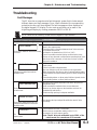
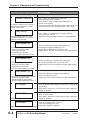
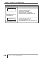
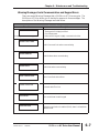
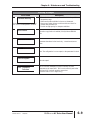
MAINTENANCE AND
TROUBLESHOOTING
CHAPTER
6
In This Chapter...
Maintenance and Inspection . . . . . . . . . . . . . . . . . . . . . . . . . .6–2
Monthly Inspection . . . . . . . . . . . . . . . . . . . . . . . . . . . . . . . . . . .6–2
Annual Inspection . . . . . . . . . . . . . . . . . . . . . . . . . . . . . . . . . . . .6–2
Recharge Capacitors (for unused drives) . . . . . . . . . . . . . . . . . . .6–2
Troubleshooting . . . . . . . . . . . . . . . . . . . . . . . . . . . . . . . . . . .6–3
Fault Messages . . . . . . . . . . . . . . . . . . . . . . . . . . . . . . . . . . . . . .6–3
Warning Messages: Serial Communication and Keypad Errors . . .6–7
Chapter 6: Maintenance and Troubleshooting
Maintenance and Inspection
Modern AC drives are based on solid state electronics technology. Preventive
maintenance is required to operate the AC drive in its optimal condition, and to
ensure a long life. We recommend that a qualified technician perform a regular
inspection of the AC drive. Some items should be checked once a month, and
some items should be checked yearly.
If the drive is stored or is otherwise unused for more than a year, the drive’s internal DC
link capacitors should be recharged before use. Otherwise, the capacitors may be
damaged when the drive starts to operate. We recommend recharging the capacitors
of any unused drive at least once per year.
WARNING! Disconnect AC power and ensure that the internal capacitors have fully
discharged before inspecting the AC drive!
Wait at least two minutes after all display lamps have turned off.
Monthly Inspection
Check the following items at least once a month.
1. Make sure the motors are operating as expected.
2. Make sure the installation environment is normal.
3. Make sure the cooling system is operating as expected.
4. Check for irregular vibrations or sounds during operation.
5. Make sure the motors are not overheating during operation.
6. Check the input voltage of the AC drive and make sure the voltage is within the
operating range. Check the voltage with a voltmeter.
Annual Inspection
Check the following items once annually.
1. Tighten and reinforce the screws of the AC drive if necessary. They may loosen
due to vibration or changing temperatures.
2. Make sure the conductors and insulators are not corroded or damaged.
3. Check the resistance of the insulation with a megohmmeter.
4. Check the capacitors and relays, and replace if necessary.
5. Clean off any dust and dirt with a vacuum cleaner. Pay special attention to
cleaning the ventilation ports and PCBs. Always keep these areas clean.
Accumulation of dust and dirt in these areas can cause unforeseen failures.
6. Recharge the capacitors of any drive that is in storage or is otherwise unused.
Recharge Capacitors (for unused drives)
Recharge the DC link before using any drive that has not been operated within a
year:
1. Disconnect the motor from the drive.
2. Apply input power to the drive for 2 hours.
6–2
DURAPULSE AC Drive User Manual
1st Ed. Rev. D
05/2013
Chapter 6: Maintenance and Troubleshooting
Troubleshooting
Fault Messages
The AC drive has a comprehensive fault diagnostic system that includes several
different alarms and fault messages. Once a fault is detected, the corresponding
protective functions will be activated. The fault messages are then displayed on
the digital keypad LCD display. The six most recent faults can be read on the
digital keypad display by viewing parameters P06.31 to P06.36.
NOTE: Faults can be cleared by a reset from the keypad or input terminal.
Fault Messages
Fault Name/Description
Corrective Actions
1. Check whether the motor's horsepower is equal to or less than
the AC drive output power.
2. Check the wiring connections between the AC drive and motor
The AC drive detects an abnormal increase for possible short circuits.
3. Increase the Acceleration time (P 1.01 or P 1.05).
in current.
4. Check for possible excessive loading conditions at the motor.
5. If there are any abnormal conditions when operating the AC drive
after short-circuit is removed, or fault does not clear, call ADC
Support for assistance.
OVER-CURRENT
OVER-VOLTAGE
The AC drive detects that the DC bus
voltage has exceeded its maximum
allowable value.
OVER-TEMPERATURE
The AC drive temperature sensor detects
excessive heat.
1. Check whether the input voltage falls within the rated AC drive
input voltage.
2. Check for possible voltage transients.
3. Bus over-voltage may also be caused by motor regeneration.
Either increase the decel time or add an optional braking resistor.
4. Check whether the required braking power is within the specified
limits.
5. Check braking resistor on drives under 20HP and dynamic brake
unit & braking resistor on drives 20HP and above.
1. Ensure that the ambient temperature falls within the specified
temperature range.
2. Make sure that the ventilation holes are not obstructed.
3. Remove any foreign objects on the heat sinks and check for
possible dirty heat sink fins.
4. Provide enough spacing for adequate ventilation.
UNDER-VOLTAGE
The AC drive detects that the DC bus
voltage has fallen below its minimum
allowable value.
OVERLOAD
The AC drive detects excessive drive
output current.
1st Ed. Rev. D
05/2013
Check whether the input voltage falls within the rated AC drive
input voltage.
1. Check whether the motor is overloaded.
2. Reduce torque compensation setting as set in P 2.03.
3. Increase the AC drive’s output capacity.
Note: The AC drive can withstand up to 150% of the
rated current for a maximum of 60 seconds.
DURAPULSE AC Drive User Manual
6–3
Chapter 6: Maintenance and Troubleshooting
Fault Messages
Fault Name/Description
Corrective Actions
THERMAL OVERLOAD
If P 6.07 is set to ‘1’ to enable during steady state:
1. Check for possible motor overload.
2. Check electronic thermal overload relay setting (P 6.00)..
3. Increase motor capacity.
4. Reduce the current level so that the AC drive output current does
not exceed the value set by the Motor Rated Current P 0.01.
Parameter settings (P 6.07 to P 6.09)
An external condition has occurred to
cause an internal electronic or motor
thermal overload fault
OVER-TORQUE
Parameter settings (P 6.07 to P 6.09)
An external condition has occurred to
cause an over-torque fault.
If P 6.07 is set to ‘2’ to enable detection during accel/decel:
1. Reduce the motor overload.
2. Adjust the over-torque detection setting to an appropriate level.
OVER-CURRENT ACC
Over-current during acceleration:
1. Short-circuit at motor output.
2. Torque boost too high.
3. Acceleration time too short.
4. AC drive output capacity is too small.
1. Check for possible poor insulation at the output line.
2. Decrease the torque boost setting in P 2.02.
3. Increase the acceleration time P 1.01 and P 1.05.
4. Replace the AC drive with one that has a higher output capacity.
OVER-CURRENT DEC
Over-current during deceleration:
1. Short-circuit at motor output.
2. Deceleration time too short.
3. AC drive output capacity is too small.
1. Check for possible poor insulation at the output line.
2. Increase the deceleration time P 1.02 and P 1.06.
3. Replace the AC drive with one that has a higher output capacity.
OVER-CURRENT STD
Over-current during steady state operation
1. Short-circuit at motor output.
2. Sudden increase in motor loading.
3. AC drive output capacity is too small.
1. Check for possible poor insulation at the output line.
2. Check for possible motor stall.
3. Replace the AC drive with one that has a higher output capacity.
1. Switch off power supply.
2. Check whether the input voltage falls within the AC drive's rated
input voltage.
3.
Switch the AC drive back on. If fault does not clear, contact ADC
Internal memory IC cannot be programmed
Support for assistance.
CPU FAILURE 1
CPU FAILURE 2
Internal memory IC cannot be read.
CPU FAILURE 3
Internal memory IC failed to receive outputstatus
6–4
1. Reset drive to factory defaults P 9.08 to 99.
2. Switch off power supply
3. Switch the AC drive back on. If fault does not clear, contact ADC
Support for assistance.
1. Check all connections at L1, L2 and L3.
2. Verify correct voltage at L1, L2,L3.
3. Contact ADC Support for assistance.
DURAPULSE AC Drive User Manual
1st Ed. Rev. D
05/2013
Chapter 6: Maintenance and Troubleshooting
Fault Messages
Fault Name/Description
HARDWARE FAILURE
Hardware protection failure
Corrective Actions
1. Check all connections at L1, L2 and L3.
2. Verify correct voltage at L1, L2,L3.
3. Contact ADC Support for assistance.
MOM POWER LOSS
Check line power to drive
Input power has been lost
EXTERNAL FAULT
The external terminal EF-CM goes from
OFF to ON
When external terminal EF-CM is closed, the output will be turned
off (under Normally Open. External Fault.).
AUTO RAMP FAULT
Refer to Over-current or Over-voltage error
Auto accel/decel failure
GROUND FAULT
1. Possible unbalanced load
2. Possible current leakage
EXT. BASE-BLOCK
AC drive output is turned off.
1. Check the motor for possible insulation damage.
2. Check for possible poor insulation at the output line.
1. When the external input terminal (base-block) is active, the AC
drive output will be turned off.
2. Disable this connection and the AC drive will begin to work
again.
INPUT POWER LOSS
One phase of the input power is lost
1. Check for possible poor connection on the input power line.
2. Check for possible loss of phase on input power line.
OUTPUT SHORTED
Contact ADC Support for assistance.
IGBT Short Circuit
PID FBACK LOSS
PID Warning:
PID Feedback Loss - The 4-20mA PID signal has been lost.
The corrective action can be set with the PID Feedback Loss
1. If P 7.27 = 0, (warn and AC drive stop),
parameter (P 7.27). The available settings are:
PID feedback loss recorded.
00 - Warn and AC Drive Stop
2. If P 7.27 = 1, (warn and continue
01 - Warn and Continue
operation), PID feedback loss not
The default setting is 00.
recorded.
1st Ed. Rev. D
05/2013
DURAPULSE AC Drive User Manual
6–5
Chapter 6: Maintenance and Troubleshooting
Fault Messages
Fault Name/Description
Corrective Actions
ENCODER LOSS
1. Verify that the encoder board has power
1. If P 10.05 = 1 or 2 (warn and AC drive 2. Check to be sure it is not mis-wired
stop), Encoder feedback loss would be
3. Check for incorrect voltage or encoder set-up
recorded.
4. Check both the mechanical and electrical integrity of the
2. If P 10.05 = 0 (warn and continue
encoder.
operation), Encoder feedback loss
would not be recorded.
ENC SIGNAL ERROR
1.Verify power to the encoder feedback card
2. Verify encoder and feedback card wiring
Encoder A/B phase signal is in error when 3. Check encoder feedback card dip switch settings and encoder
voltage requirements
the control mode is from the encoder
6–6
DURAPULSE AC Drive User Manual
1st Ed. Rev. D
05/2013
Chapter 6: Maintenance and Troubleshooting
Warning Messages: Serial Communication and Keypad Errors
There are several Warning Messages that a DURAPULSE AC Drive may give. The
DURAPULSE AC Drive allows you to decide its response to these messages. The
descriptions of the Warning Messages are listed below.
Warning Messages
Error Name
No display shown on the keypad
Description
1. The Keypad LCD display has failed.
2. Check input power
3. Make sure the keypad is tightly connected to the drive.
Invalid Cmd Code
Invalid Command Code when communicating
Invalid Address
Invalid Address when communicating
Invalid Data
Invalid Data when communicating
Slave Comm Fault
Slave Comm Fault device failure
Comm Time-Out
Communication Time Out
Drive Error
Drive model doesn’t match keypad
EEPROM Fault
1st Ed. Rev. D
05/2013
When the copy function is enabled (P 9.40), there is a Read/Write
EEPROM Fault
DURAPULSE AC Drive User Manual
6–7
Chapter 6: Maintenance and Troubleshooting
Warning Messages
Error Name
Description
Rating Mismatch
Data range doesn’t match
Group# Overflow
When the copy function is enabled (P 9.40), keypad’s group
number data is more than the drive’s.
No Space
When the copy function is enabled (P 9.40),EEPROM data block in
the keypad is full.
Delete Failure
When the copy function is enabled (P 9.40), delete EEPROM block
fails.
No Data
R1 Detect Error
Failure to detect motor resistance during
Auto-tune procedure
No Load Error
Failure to detect any motor load during
Auto-tune procedure
When the copy function is enabled (P 9.40), EEPROM data block
is null.
1. Check to make sure the motor is connected to the drive
correctly.
2. Check line power to drive
3. STOP key was pressed during Auto-Tune procedure
1. Check to make sure the motor is connected to the drive
correctly.
2. Check line power to drive
3. STOP key was pressed during Auto-Tune procedure
Copy Error-COMMS
1.Check connection between the keypad and drive and make sure
it is not loose
2.
Check communications protocol for correct settings
Communications error during Copy Keypad
function
Copy Error-Data
Data error during Copy Keypad function
6–8
1. Check connection between the keypad and drive and make
sure it is not loose
2. Check communications protocol for correct settings
DURAPULSE AC Drive User Manual
1st Ed. Rev. D
05/2013
Chapter 6: Maintenance and Troubleshooting
Warning Messages
Error Name
Overheat Warning
The AC drive temperature has exceeded
85% of the Over-temperature condition.
Description
1. Ensure that the ambient temperature falls within the specified
temperature range.
2. Make sure that the ventilation holes are not obstructed.
3. Remove any foreign objects on the heat sinks and check for
possible dirty heat sink fins.
4. Provide enough spacing for adequate ventilation.
Write Failure
When the copy function is enabled (P 9.40),Write to EEPROM
fails.
Parameter Locked
Parameters have been locked: read only - cannot be set/cannot
write.
--- ERR --Error: The configuration is not accepted, or the parameter is locked.
Value Accepted
Value Accepted.
Error: Duplicate
Function
1st Ed. Rev. D
05/2013
This occurs when attempting to set two mutually exclusive
parameters to the same value. This is most commonly seen when
P4.00 and P4.13 are both set to the same value.
(Firmware version 1.04 or higher only.)
DURAPULSE AC Drive User Manual
6–9
Chapter 6: Maintenance and Troubleshooting
6–10
DURAPULSE AC Drive User Manual
1st Ed. Rev. D
05/2013