1
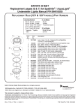
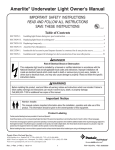
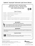
b. Hold the ends of the unitension clamp together. Insert the bolt through one end of the bend end and then
insert the other end through the other bent end and thread the bolt into the nut. Using a #3 Phillips head
screwdriver tighten the screw and nut until the distance between the ends of the clamp equals 0.6CM or
less; see Figurer 3.
F. Replace the light assembly into the niche and tighten the special pilot screw.
WARNING
UL-S100 and UL-S300
Stainless Steel Underwater Light
Operating Instruction
Use only the special pilot screw provided with this underwater light. This screw mounts and electrically
grounds the housing securely to the mounting ring and wet niche. Failure to use the screw provided could create
an electrical hazard which could result in death or serious injury to pool users, installers or others due to
electrical shock.
G. Fill pool until the underwater light is completely submerged in water before operating the light for
more than 10 seconds. Turn on main switch or circuit breaker, as well as the switch which specifically
operates the underwater light, to check for proper operation.
ORIENTATION OF WIRE CLAMP AND BOLT CONNECTION
CIRCULAR CLAMP
A
0.6CM OR LESS
90 DEGREES
PILOT SCREW
POSITION OF CIRCULAR CLAMP
PILOT SCREW
PILOT SCREW
BOLT IS TO BE TIGHTENED AT APPROX. 90 DEGREES
FROM THE PILOT SCREW ON THE FACE RING AS SHOWN ABOVE.
Figure 3
Figure 2
PLEASE READ THE FOLLOWING CAREFULLY AND
KEEP THIS USER MANUAL SAVE FOR FUTURE REFERENCE
1
8
2
3
Item
4
5
6
7
Underwater Light Replacement Parts
Description
1
Part
Number
040201
2
040901
Face ring assembly
3
040902
Wire with nut
4
040903
Bolt
5
040904
Lens
6
040905
Gasket
7
040906
Floodlamp 300W/12V
8
040201
Pilot screw
9
040202
Face ring assembly
10
040203
Wire with nut
11
040204
Bolt
12
040205
Gasket
13
040207
Lens
14
040206
Floodlamp 100W12V
9
DANGER
RISK OF ELECTRICAL SHOCK OR ELECTROCUTION
Pilot screw
10
11
12
13
This underwater light fixture must be installed by a licensed or certified electrician or a qualified serviceman in
accordance to the requirements of your government standard or local authorities. Improper installation will create
electric hazards which could result in serious injury, death as well as damage to the property. Before servicing the
light, disconnect the power supply from the circuit breaker. Failure to do so could result in serious injury, death
and or damage to the property.
WARNING
Before installing this underwater light, read and follow all warning notices and instructions accompanying this
light. Failure to follow safety warnings and instructions can result in severe injury, death, or property damage.
14
Important Notice
Attention Installer.
This manual contains important information about the installation, operation and safe use of this product.
This information should be given to the owner/operator of this equipment.
EMLI06083035
4-4
1-4
I. Installing light fixture during new pool construction.
A. The electrician must complete preparatory steps before light fixture is installed;
see Figure 1.
120CM MIN.
TO GFCI. CIRCUIT
BREAKER AND
POWER SOURCE
2. Cut the cord at the Junction BOX, leaving at least 15CM of cord to make connections.
3. Strip 15CM of the outer cord jacket to expose the three insulated wires. Be careful not to damage the
insulation on the three (3) inner wires.
4. Connect all three (3) wires to the corresponding circuit wires in the Junction Box, and secure the Junction
Box cover in place.
WARNING
10CM MIN.
20CM MIN. JUNCTION BOX OR
LOW VOLTAGE TRANSFORMER
Never operate this Underwater Light for more than 10 seconds unless it is totally submerged in water. Without
total submersion, the light assembly will get extremely hot, which may result in serious injury to pool users,
installers, or bystanders, or in damage to property.
5. Replace the light assembly into niche and tighten special pilot screw.
WARNING
2.5 CM RIGID CONDUIT
45.5CM MIN. FROM WATER LINE
TO TOP OF LENS
#8 AWG GROUND CONNECTOR BONDED TO REBAR.
CONCRETE MUST BE CUT BACK
AROUND NICHE TO ALLOW FOR
A COMPACTED PLASTER SEAL.
Use only the special stainless steel pilot screw provided with Underwater Light. Failure to use the screw
provided could create an electrical hazard which could result in death or serious injury to pool users, installers
or others due to electrical shock.
6. Fill the pool until the underwater light is completely submerged in water before operating the light for more
than 10 seconds. Turn on main switch or circuit breaker, as well as the switch which operates the underwater
light itself, to check for proper operation.
II. Replacing a lamp only:
DANGER
Always disconnect power to the pool light at the circuit breaker before servicing the light. Failure to do so could
result in death or serious injury to installer, servicemen, pool users, or others due to electrical shock.
Figure 1.
1. Ensure that the pool meets the requirements of the current National Electrical Code and all local codes and
ordinances. A licensed or certified electrician must install the electrical system to meet or exceed those
requirements before the underwater light is installed. Some of the requirements of the National Electrical
Code which the Pool's electrical system must meet are as follows.
a. The lighting circuit must have a Ground Fault Circuit Interrupter (GFCI), and must have an appropriately
rated circuit breaker.
b. The Junction Box (or, for 12 volt models, the low voltage transformer) must be located at least 20CM
above water level, at least 10CM above ground level, and at least 120CM from the edge of the pool; see
Figure 1.
c. The light fixture and all metal items within 152CM of the pool must be properly electrically bonded.
d. The wet niche must be properly installed so that the top edge of the underwater light's lens is at least 45.5
below the surface of the water in the pool; see Figure 1.
e. The wet niche must be properly electrically bonded and grounded via the No.8 AWG ground connector
located at the rear of the niche; see Figure 1.
NOTE: The pool or spa electrical system can be verified with a pool and Spa Electrical Qualification Test kit.
The electrical system inspection using this kit must be performed by trained and certified personnel.
2. To be certain that pool's electrical system meets all applicable requirements, the electrician should also
consult the local building department.
B. Steps to perform after the electrical system requirements are met.
1. Feed cord through conduit to Junction Box, leaving at least 120CM of cord at the light fixture to coil around
the light; see Figure 1. This 120CM of cord around the light allows the light to be serviced after the pool is
filled with water.
2-4
A. Turn off main electrical switch or circuit breaker, as well as the switch which operates the underwater
light itself.
B. You will need the following items:
1. A new lens gasket.
2. A lamp, refer to Table 1 for the correct type and wattage.
WARNING
Replace lamp with a similar type and wattage. Failure to replace lamp with the same type of lamp will damage
the light assembly and may cause an electrical hazard resulting in death or serious injury to pool users,
installers, or others due to electrical shock, and may also cause damage to property.
C. To remove light assembly, remove the special pilot screw at top of face ring, remove light assembly
from niche, and place assembly on deck.
D. Disassemble light fixture and remove bulb. Remove and discard old gasket.
E. Secure the face ring to the light fixture. Sealing screws must be tightened in the following manner to
ensure a proper seal.
1. For lights with stainless face ring:
a. Partly tighten the screw at the 3 o'clock position, and then partly tighten the screw at the 9 o'clock
position. Partly tighten the screw at another 'opposite' position, and then partly tighten the screw
directly across from it.
b. Continue partly tightening all screws in the above sequence until all screws are evenly and securely
tightened. Recommended 50CM pounds torque.
2. For lights with stainless steel face ring:
a. With the bent ends of the circular unitension clamp pointing down spread the clamp and place it in the
"U" recesses of the locking levers. Ensure that the bent ends of the clamp are located between the pair of
locking levers as shown in Figure 2, location A Check to see that the clamp is properly engaged with all
of the levers; see Figurer 2.
3-4