1
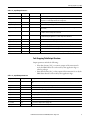
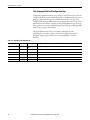
Reference Manual
Rockwell Automation Library of Process Objects:
Tank Strapping Table (P_StrapTbl)
Version 3.1
Important User Information
Read this document and the documents listed in the additional resources section about installation, configuration, and
operation of this equipment before you install, configure, operate, or maintain this product. Users are required to
familiarize themselves with installation and wiring instructions in addition to requirements of all applicable codes, laws,
and standards.
Activities including installation, adjustments, putting into service, use, assembly, disassembly, and maintenance are required
to be carried out by suitably trained personnel in accordance with applicable code of practice.
If this equipment is used in a manner not specified by the manufacturer, the protection provided by the equipment may be
impaired.
In no event will Rockwell Automation, Inc. be responsible or liable for indirect or consequential damages resulting from the
use or application of this equipment.
The examples and diagrams in this manual are included solely for illustrative purposes. Because of the many variables and
requirements associated with any particular installation, Rockwell Automation, Inc. cannot assume responsibility or
liability for actual use based on the examples and diagrams.
No patent liability is assumed by Rockwell Automation, Inc. with respect to use of information, circuits, equipment, or
software described in this manual.
Reproduction of the contents of this manual, in whole or in part, without written permission of Rockwell Automation,
Inc., is prohibited.
Throughout this manual, when necessary, we use notes to make you aware of safety considerations.
WARNING: Identifies information about practices or circumstances that can cause an explosion in a hazardous environment,
which may lead to personal injury or death, property damage, or economic loss.
ATTENTION: Identifies information about practices or circumstances that can lead to personal injury or death, property
damage, or economic loss. Attentions help you identify a hazard, avoid a hazard, and recognize the consequence.
IMPORTANT
Identifies information that is critical for successful application and understanding of the product.
Labels may also be on or inside the equipment to provide specific precautions.
SHOCK HAZARD: Labels may be on or inside the equipment, for example, a drive or motor, to alert people that dangerous
voltage may be present.
BURN HAZARD: Labels may be on or inside the equipment, for example, a drive or motor, to alert people that surfaces may
reach dangerous temperatures.
ARC FLASH HAZARD: Labels may be on or inside the equipment, for example, a motor control center, to alert people to
potential Arc Flash. Arc Flash will cause severe injury or death. Wear proper Personal Protective Equipment (PPE). Follow ALL
Regulatory requirements for safe work practices and for Personal Protective Equipment (PPE).
Allen-Bradley, Rockwell Software, Rockwell Automation, RSLogix, Logix5000, FactoryTalk, PlantPAx, and ControlLogix are trademarks of Rockwell Automation, Inc.
Trademarks not belonging to Rockwell Automation are property of their respective companies.
Table of Contents
Preface
Software Compatibility and Content Revision. . . . . . . . . . . . . . . . . . . . . . . . 5
Additional Resources . . . . . . . . . . . . . . . . . . . . . . . . . . . . . . . . . . . . . . . . . . . . . . . 6
Tank Strapping Table (P_StrapTbl)
Guidelines . . . . . . . . . . . . . . . . . . . . . . . . . . . . . . . . . . . . . . . . . . . . . . . . . . . . . . . . . 7
Functional Description . . . . . . . . . . . . . . . . . . . . . . . . . . . . . . . . . . . . . . . . . . . . . 7
Required File . . . . . . . . . . . . . . . . . . . . . . . . . . . . . . . . . . . . . . . . . . . . . . . . . . . . . . 8
Controller Code . . . . . . . . . . . . . . . . . . . . . . . . . . . . . . . . . . . . . . . . . . . . . . . . . . . 8
Tank Strapping Table InOut Structure. . . . . . . . . . . . . . . . . . . . . . . . . . . 8
Tank Strapping Table Input Structure . . . . . . . . . . . . . . . . . . . . . . . . . . . 8
Tank Strapping Table Output Structure . . . . . . . . . . . . . . . . . . . . . . . . . 9
Tank Strapping Table Local Configuration Tags . . . . . . . . . . . . . . . . 10
Operations . . . . . . . . . . . . . . . . . . . . . . . . . . . . . . . . . . . . . . . . . . . . . . . . . . . . . . 11
No Modes or Alarms . . . . . . . . . . . . . . . . . . . . . . . . . . . . . . . . . . . . . . . . . 12
Simulation . . . . . . . . . . . . . . . . . . . . . . . . . . . . . . . . . . . . . . . . . . . . . . . . . . . 12
Execution. . . . . . . . . . . . . . . . . . . . . . . . . . . . . . . . . . . . . . . . . . . . . . . . . . . . 12
Programming Example . . . . . . . . . . . . . . . . . . . . . . . . . . . . . . . . . . . . . . . . . . . 13
Rockwell Automation Publication SYSLIB-RM033C-EN-P - August 2014
3
Table of Contents
Notes:
4
Rockwell Automation Publication SYSLIB-RM033C-EN-P - August 2014
Preface
This document is updated throughout for version 3.1 of the Rockwell
Automation Library of Process Objects. Changes for this revision are marked by
change bars shown in the right margin.
Software Compatibility and
Content Revision
Table 1 - Summary of Changes
Topic
Page
Changed title from 'PlantPAx Library of Process Objects' to 'Rockwell Automation Library of Process
Objects'
Front Cover
Changed version of Rockwell Automation Library of Process Objects from 3.0 to 3.1
5, 8
Changed references to Knowledgebase Answer ID 62682 to Product Compatibility and Download
Center
5
Additional Resources table - added Rockwell Automation Library of Process Objects: Basic Analog
Input Reference Manual, publication SYSLIB-RM001
6
Input/Output Parameters Tables - Added 'Alias For' column
8, 9
Operations - added Simulation section
12
For the latest compatible software information and to download the Rockwell
Automation Library, see the Product Compatibility and Download Center at
http://www.rockwellautomation.com/rockwellautomation/support/pcdc.page.
For general library considerations, see Rockwell Automation Library of Process
Objects, publication PROCES-RM002.
Rockwell Automation Publication SYSLIB-RM033C-EN-P - August 2014
5
Preface
Additional Resources
These documents contain additional information concerning related products
from Rockwell Automation.
Resource
Description
PlantPAx Process Automation System Selection Guide,
publication PROCES-SG001
Provides information to assist with equipment
procurement for your PlantPAx system.
PlantPAx Process Automation System Reference Manual,
publication PROCES-RM001
Provides characterized recommendations for
implementing your PlantPAx system.
Rockwell Automation Library of Process Objects,
publication PROCES-RM002
Provides general considerations for the PlantPAx system
library of process objects.
FactoryTalk View Machine Edition User Manual,
publication VIEWME-UM004
Provides details on how to use this software package for
creating an automation application.
FactoryTalk View Site Edition User Manual,
publication VIEWSE-UM006
Provides details on how to use this software package for
developing and running human-machine interface
(HMI) applications that can involve multiple users and
servers, distributed over a network.
Logix5000™ Controllers Add-On Instructions Programming
Manual, publication 1756-PM010
Provides information for designing, configuring, and
programming Add-On Instructions.
Rockwell Automation Library of Process Objects: Basic
Analog Input Reference Manual, publication SYSLIB-RM001
Provides information on how to use the Add-On
Instruction to monitor one analog value, typically from
a channel of an analog input module, and deal with
alarms when the analog value exceeds user-specified
thresholds (high and low).
You can view or download publications at
http:/www.rockwellautomation.com/literature/. To order paper copies of
technical documentation, contact your local Allen-Bradley distributor or
Rockwell Automation sales representative.
6
Rockwell Automation Publication SYSLIB-RM033C-EN-P - August 2014
Tank Strapping Table (P_StrapTbl)
Function Block
The P_StrapTbl (Tank Strapping Table) Add-On Instruction calculates the
volume of product in an upright cylindrical tank, given the level of the product
and the tank calibration table. This instruction can optionally compensate for
free water at the bottom of the tank (given a product/water interface level) or for
thermal expansion of the tank shell (given the coefficient of linear expansion of
the shell material and product and ambient temperatures).
This instruction also can optionally compensate for a floating tank roof if the
product density is provided.
Guidelines
Use this instruction in these situations:
• You want to determine the volume of product in an upright cylindrical
tank given its level.
• You have the Strapping Table (tank calibration table) data for the tank.
This instruction interpolates level between strapping table calibration points
linearly. Do not use this instruction if you have a spherical tank, a conical tank, or
other tank shape for which the volume does not vary more-or-less linearly with
level.
To determine the mass of product in the tank, take the volume result from the
P_StrapTbl instruction and compensate for product density with further
calculations. See the American Petroleum Institute (API) Manual of Petroleum
Measurement Standards (MPMS) for the appropriate calculations.
Functional Description
The P_StrapTbl instruction is intended only as a calculation function, between
other blocks, and so no HMI components are provided.
For a faceplate or alarm, send the calculated corrected volume to a P_AIn
(Analog Input) instruction. See the Rockwell Automation Library of Process
Objects: Basic Analog Input (P_AIn) Reference Manual,
publication SYSLIB-RM001, for alarming and display information.
Rockwell Automation Publication SYSLIB-RM033C-EN-P - August 2014
7
Tank Strapping Table (P_StrapTbl)
The Add-On Instruction import, P_StrapTbl_3_1-00_AOI.L5X, must be
imported into the controller project to use the instruction in the project. The
service release number (boldfaced) can change as service revisions are created.
Required File
The import file can be downloaded from the Product Compatibility and
Download Center at
http://www.rockwellautomation.com/rockwellautomation/support/pcdc.page.
There are no visualization files because the P_StrapTbl object does not use
display elements or faceplates.
This section describes the parameter references for this Add-On Instruction.
Controller Code
Tank Strapping Table InOut Structure
InOut parameters are used to link the Add-On Instruction to external tags that
contain necessary data for the instruction to operate. These external tags must be
of the data type shown.
InOut Parameter
Data Type
Description
Cfg_CalTbl
P_StrapTblRow[N]
Tank calibration table (level to volume), each entry containing the following members:
• Major (Real): Number of major units (feet, meters)
• Minor (Real): Number of minor units (inches, centimeters, millimeters)
• Volume (Real): Tank volume (barrels, gallons, liters) at a given level
The array size [N] must be greater than or equal to the number of calibration points provided in the strapping table.
IMPORTANT: Make this array long enough to hold all of the strapping table entries for your tank. For example, if
your tank is 30 ft tall and the strapping table provides data every inch, create a tag of type P_StrapTblRow[361]
(361 entries = empty row+ 30 x 12 data rows).
Tank Strapping Table Input Structure
Input parameters include the following:
• Input data elements (Inp_) are typically used to connect field inputs from
I/O modules or signals from other objects.
• Configuration data elements (Cfg_) are used to set configurable
capabilities and features of the instruction.
Table 2 - P_StrapTbl Input Parameters
8
Input Parameter
Data Type
Default
Description
EnableIn
BOOL
1
Ladder Diagram:
If the rung-in condition is true, the instruction’s Logic routine executes. If the rung-in condition is false,
the instruction’s EnableInFalse routine executes.
Function Block Diagram:
If true, or not connected, the instruction’s Logic routine executes. If the parameter is exposed as a pin
and wired, and the pin is false, the instruction’s EnableInFalse routine executes.
Structured Text:
No effect. The instruction’s Logic routine executes.
Inp_Level
REAL
0.0
Input: Tank innage level (feet or meters).
Rockwell Automation Publication SYSLIB-RM033C-EN-P - August 2014
Tank Strapping Table (P_StrapTbl)
Table 2 - P_StrapTbl Input Parameters
Input Parameter
Data Type
Default
Description
Inp_FWLevel
REAL
0.0
Input: Tank innage free water (interface) level (feet or meters).
Inp_ObsAPI
REAL
30.5
Input: Observed density (degrees API) at product temperature. This is used for floating roof
compensation to calculate displacement based on weight of roof.
Inp_AvgProdTemp
REAL
60.0
Input: Average product temperature (degrees Fahrenheit or Celsius).
Inp_AmbTemp
REAL
60.0
Input: Ambient temperature (degrees Fahrenheit or Celsius).
Cfg_MinorPerMajor
REAL
12.0
Table Minor units (inches, centimeters, millimeters) per major unit (feet or meters) (type 0.0 if minor
units not used).
Cfg_HasCTSh
BOOL
0
0 = No correction for temperature of tank shell.
1 = Include correction for temperature of tank shell.
Cfg_HasFRA
BOOL
0
0 = Do not use floating roof adjustment.
1 = Include floating roof adjustment to account for displacement of fluid level.
Cfg_CalTemp
REAL
60.0
Temperature of tank calibration (typically 60 °F or 15 °C).
Cfg_ShellCoefOfExp
REAL
6.2E-06
Tank shell linear coefficient of thermal expansion (1 per degree Fahrenheit or 1 per Celsius).
Cfg_K
REAL
7.0
Temperature weighting (type 0.0 for insulated tank) (see API MPMS 2.2A app. D).
Cfg_FloatRoofLevel
REAL
0.0
Lowest level at which to add/subtract floating roof compensation (feet).
Cfg_FloatRoofCalAPI
REAL
30.5
Degrees API for which table includes floating roof data.
Cfg_FloatRoofVolPerAPI
REAL
-2.5
Adjustment to table values for API <> CalAPI (volume/degrees API, typically a negative number).
Tank Strapping Table Output Structure
Output parameters include the following:
• Value data elements (Val_) are numeric outputs of the instruction for
use by the HMI. Values also can be used by other application logic or
software packages.
• Status data elements (Sts_) are bit outputs of the instruction for use by the
HMI. Status bits also can be used by other application logic.
Table 3 - P_StrapTbl Output Parameters
Output Parameter
Data Type
Description
EnableOut
BOOL
Enable output: The EnableOut signal is not manipulated by this instruction. Its output state always reflects EnableIn input
state.
Val_TOV
REAL
Raw total observed volume from Cal. Table (barrels, gallons, liters).
Val_FW
REAL
Free Water Volume (barrels, gallons, liters).
Val_TSh
REAL
Calculated tank shell temperature (degrees Fahrenheit or Celsius).
Val_CTSh
REAL
Correction for temperature of tank shell (multiplier).
Val_FRA
REAL
Floating roof adjustment volume (barrels, gallons, liters).
Val_GOV
REAL
Primary value: Gross observed volume (see API MPMS 12.1.1).
Sts_UnderMin
BOOL
Inp_Level is below lowest level in strapping table.
Sts_OverMax
BOOL
Inp_Level is above highest level in strapping table.
P_StrapTbl
BOOL
Unique parameter name for auto-discovery.
Rockwell Automation Publication SYSLIB-RM033C-EN-P - August 2014
9
Tank Strapping Table (P_StrapTbl)
Tank Strapping Table Local Configuration Tags
Configuration parameters that are array, string, or structure data types cannot be
configured as parameters for Add-On Instructions. Configuration parameters of
these types appear as local tags to the Add-On Instruction. Local tags can be
configured with RSLogix 5000 software by opening the Instruction Logic of the
Add-On Instruction instance and then opening the Data Monitor on a local tag.
These parameters cannot be modified by using controller logic or RSLogix 5000
software export/import functionality.
The P_StrapTbl instruction does not include visualization elements
(global objects or faceplates). However, these local configuration tags for
descriptive strings are provided for use in custom visualization elements
if desired.
Table 4 - P_StrapTbl Local Configuration Tags
Tag Name
Data Type
Default
Description
Cfg_Desc
STRING_40
'Tank Strapping
Table'
Description for display on HMI. This string is shown in the title bar of the faceplate.
Cfg_Label
STRING_20
'Strapping Table'
Label for graphic symbol displayed on HMI. This string appears on the graphic symbol.
Cfg_LevelIEU
STRING_8
'Feet'
Level engineering units for display on HMI.
Cfg_Tag
STRING_20
'P_StrapTbl'
Tagname for display on HMI. This string is shown in the title bar of the faceplate.
Cfg_TempEU
STRING_8
'Deg F'
Temperature engineering units for display on HMI
Cfg_VolumeEU
STRING_8
'Gallons'
Volume engineering units for display on HMI.
10
Rockwell Automation Publication SYSLIB-RM033C-EN-P - August 2014
Tank Strapping Table (P_StrapTbl)
Operations
The P_StrapTbl Add-On Instruction uses tank calibration data and a tank level
measurement to calculate tank volume. Tank calibration data can be obtained
from the tank manufacturer or design firm, or determined through calibration.
Example calibration methods are provided by the American Petroleum Institute's
(API) Manual of Petroleum Measurement Standards (MPMS) section 2.2A
or 2.2B.
This instruction performs its calculations by using the same methods described in
API MPMS Section 12.1 Part 1. The instruction calculates the following items:
• Total Observed Volume (TOV)
• Free Water Volume (FW)
• Correction for Temperature of Tank Shell (CTSh)
• Floating Roof Adjustment (FRA)
• Gross Observed Volume (GOV, the primary output of this instruction)
All calculations require the overall level input and the tank calibration table
(‘strapping table’). The FW calculation is a specific requirement when calculating
petroleum storage to adjust for free water content. This requires an additional
level signal for the product/water interface.
The CTSh calculation compensates for thermal expansion of the storage tank. If
used, this calculation requires these measurements and configuration settings:
• Product temperature and the ambient temperature
• Configuration of the tank shell coefficient of linear expansion (fraction
per degree)
• Calibration temperature for the tank calibration table
• Configuration constant for weighting the two measured temperatures
(a reasonable default is provided)
The FRA calculation compensates the level measurement for displacement
caused by a floating roof. This calculation requires a measurement or input of the
product actual density and additional configuration data about the floating roof.
The final GOV calculation is provided without correction for product density
and temperature (other than the shell temperature above) or included sediment
and water. Those calculations depend on the product, not just the tank
calibration table, and are beyond the scope of this general-purpose instruction.
Rockwell Automation Publication SYSLIB-RM033C-EN-P - August 2014
11
Tank Strapping Table (P_StrapTbl)
No Modes or Alarms
The P_StrapTbl Add-On Instruction only performs calculations and does not
have any modes or alarms. The instruction does not contain any embedded
P_Mode or P_Alarm instructions.
To provide High-High, High, Low, and/or Low-Low threshold alarms for the
input or output of P_StrapTbl, use the P_AIn Analog Input instruction.
Refer to the Rockwell Automation Library of Process Objects: Basic Analog
Input (P_AIn) Reference Manual, publication SYSLIB-RM001, for more
information.
Simulation
The P_StrapTbl Add-On Instruction does not have simulation capability.
Use the simulation capability of associated analog input instructions to simulate
level or temperature inputs or volume outputs.
Execution
The following table explains the handling of instruction execution conditions.
Condition
Description
EnableIn False (false rung)
No EnableInFalse logic is provided. The instruction
maintains its last state when EnableIn is false.
Powerup (prescan, first scan)
No Pre-scan or First Scan logic is provided. The P_StrapTbl
instruction simply performs its calculation every scan
when EnableIn is true.
Postscan
No SFC Postscan logic is provided.
Refer to the Logix5000 Controllers Add-On Instructions Programming Manual,
publication 1756-PM010, for more information.
12
Rockwell Automation Publication SYSLIB-RM033C-EN-P - August 2014
Tank Strapping Table (P_StrapTbl)
Programming Example
This example uses the P_StrapTbl instruction to calculate the volume of product
in a storage tank based on the measured storage tank level and storage tank
strapping table information. In this example, there is no floating roof so there is
no compensation for displacement. There are no adjustments based on
temperature to account for thermal expansion of the tank.
The measured storage tank level is connected into the P_StrapTbl instruction by
using the input Inp_Level. In this example, the level is reported in units of feet.
The storage tank is a 4 ft tall tank, and strapping table information has been
provided by the tank vendor. Strapping tables often list data in terms of
major and minor units. In this example, data has been provided at 6-in
increments. The vendor-provided strapping table has nine rows and looks like
the following table.
Level (ft-in.)
Volume (barrels)
0-00
3.1
0-06
136.6
1-00
264.2
1-06
402.7
2-00
541.4
2-06
692.7
3-00
844.1
3-06
990.8
4-00
1137.5
To store the strapping table information in the controller, the tag
Tank1013StrapTbl is created as type P_StrapTblRow[9] (a nine-element array of
strapping table information).
Rockwell Automation Publication SYSLIB-RM033C-EN-P - August 2014
13
Tank Strapping Table (P_StrapTbl)
The parameter Cfg_MinorPerMajor is left at its default of 12, so that the
instruction can convert the input (feet) to major and minor units (feet and
inches). This allows the strapping table to be configured by using the same major
and minor units as provided by the vendor.
Table 5 - Strapping Table Calculation Examples
.Major
.Minor
.Volume
Tank1013StrapTbl[0]
0
0
3.1
Tank1013StrapTbl[1]
0
6
136.6
Tank1013StrapTbl[2]
1
0
264.2
Tank1013StrapTbl[3]
1
6
402.7
Tank1013StrapTbl[4]
2
0
541.4
Tank1013StrapTbl[5]
2
6
692.7
Tank1013StrapTbl[6]
3
0
844.1
Tank1013StrapTbl[7]
3
6
990.8
Tank1013StrapTbl[8]
4
0
1137.5
The InOut tag Cfg_CalTbl of the P_StrapTbl instruction is modified to point to
the new array Tank1013StrapTbl to provide the instruction with the strapping
table information. The output of P_StrapTbl is then connected to another
P_AIn instruction. The output is the calculated volume of the storage tank.
The local configuration tags Cfg_Desc, Cfg_Label, and Cfg_Tag are not
required to be set. The P_StrapTbl instruction does not include visualization
elements (global objects or faceplates). However, these string parameters are
provided for use in custom visualization elements, if desired.
14
Rockwell Automation Publication SYSLIB-RM033C-EN-P - August 2014
Rockwell Automation Support
Rockwell Automation provides technical information on the Web to assist you in using its products.
At http://www.rockwellautomation.com/support you can find technical and application notes, sample code, and links to
software service packs. You can also visit our Support Center at https://rockwellautomation.custhelp.com/ for software
updates, support chats and forums, technical information, FAQs, and to sign up for product notification updates.
In addition, we offer multiple support programs for installation, configuration, and troubleshooting. For more
information, contact your local distributor or Rockwell Automation representative, or visit
http://www.rockwellautomation.com/services/online-phone.
Installation Assistance
If you experience a problem within the first 24 hours of installation, review the information that is contained in this
manual. You can contact Customer Support for initial help in getting your product up and running.
United States or Canada
1.440.646.3434
Outside United States or Canada
Use the Worldwide Locator at http://www.rockwellautomation.com/rockwellautomation/support/overview.page, or contact your local
Rockwell Automation representative.
New Product Satisfaction Return
Rockwell Automation tests all of its products to help ensure that they are fully operational when shipped from the
manufacturing facility. However, if your product is not functioning and needs to be returned, follow these procedures.
United States
Contact your distributor. You must provide a Customer Support case number (call the phone number above to obtain one) to your
distributor to complete the return process.
Outside United States
Please contact your local Rockwell Automation representative for the return procedure.
Documentation Feedback
Your comments will help us serve your documentation needs better. If you have any suggestions on how to improve this
document, complete this form, publication RA-DU002, available at http://www.rockwellautomation.com/literature/.
Rockwell Automation maintains current product environmental information on its website at
http://www.rockwellautomation.com/rockwellautomation/about-us/sustainability-ethics/product-environmental-compliance.page.
Rockwell Otomasyon Ticaret A.Ş., Kar Plaza İş Merkezi E Blok Kat:6 34752 İçerenköy, İstanbul, Tel: +90 (216) 5698400
Publication SYSLIB-RM033C-EN-P - August 2014
Supersedes Publication SYSLIB-RM033B-EN-P - September 2013
Copyright © 2014 Rockwell Automation, Inc. All rights reserved. Printed in the U.S.A.