1
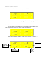
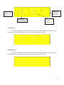
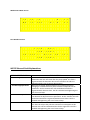
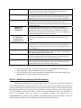
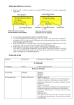
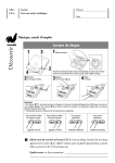
ML70S LCD Screen Usage Lift position and some datas are screened on LCD on ML70S card. When the car is on stand by position, floor number is on LCD topper line. Floor data F l o o r : 0 1 0 0 : 0 0 Direction data D i r . : U p Information screen C L : ± W a i t C a l l F l o o r : 0 1 0 0 : 0 0 T a r g e t : 0 5 Clock data Car lamp is ON or OFF Floor data D i r . : U p Target floor C L : + Information screen U p H i g h S p e e d Clock data When the car is moving, on the left side of LCD third line, there is target floor. ML70S Button Usage Explanations There are four buttons at the right side of M70S card. Some functions are appointed to these buttons except the situation that the car is stopped, stop signal is off or stop signal is cut and re‐ applied and inspection mode. ENTER BUTTON (Red) : Manual movement mode is started when pressed this button. At this situation, if safety circuit is OK, the car is moved with UP and DOWN buttons. Soft stop is done at the end of the movements for Speed Control Systems. ESC button must be pressed to exit Manual Movement mode. UP BUTTON (Brown): Situation screens are shown in order when pressed this button. The explanations related this function will be done below. DOWN BUTTON (Brown): Car calls function is started when pressed this buton. The explanations related this function will be done below. ESC BUTTON (Black): Registered fault observing function is started when pressed this button. The explanations related this function will be done below. 1 SITUATON SCREENS TRACING Situation screens datas can be reached with up buton and looked at between the screens. Car Cards Communication Screen F l o o r : 0 1 K a b i n ‐ R : ± 0 0 : 0 0 K a b i n ‐ K > A 1 ± A 2 ± B 1 ± B 2 ± G r o u p I D ‐ A : ± If there is communication with ML70S card, the sign will be “+” and if not, the sign will be “‐”. Floor Card Communication Screen This screen is belong to floor card near door A, if floor number is is bigger than 16, the second screen will be traced. The same situation is exist for the floor card near door B. F l o o r C A N C o m m . 0 0 0 0 0 0 0 0 0 0 1 1 1 1 1 1 0 1 2 3 4 5 6 7 8 9 0 1 2 3 4 5 + + + + + ‐ ‐ ‐ ‐ ‐ ‐ ‐ ‐ ‐ ‐ ‐ ‐ A If there is communication with ML70S card, the sign will be “+” and if not, the sign will be “‐”. Door Situation and Signals Screen Shown that “OPEN” signal exist F l o o r : 0 1 D O O R A S I T U A T I O N O P E N : * C L O S E : ‐ D o o r O p e n 0 0 : 0 0 F C : ‐ Shown that “PHOTOCELL” signal exist Shown that Door A situation Shown that “CLOSE” signal exist 2 Shown that “OPEN” signal exist F l o o r : 0 1 D O O R B S I T U A T I O N O P E N : ‐ C L O S E : ‐ D o o r O p e n 0 0 : 0 0 F C : * Shown that “PHOTOCELL” signal exist Shown that “CLOSE” signal exist Shown that Door B situation Car Calls Screen This screen is belong to floor card near door A, if floor number is is bigger than 16, the second screen will be traced. The same situation is exist for the floor card near door B. C a r C a l l s ‐ A 0 0 0 0 0 0 0 0 0 0 1 1 1 1 1 1 0 1 2 3 4 5 6 7 8 9 0 1 2 3 4 5 . . . . + . . + . . . + . . . . Floor Calls Screen This screen is belong to floor card near door A, if floor number is is bigger than 16, the second screen will be traced. The same situation is exist for the floor card near door B. U p . . + . . + . . . . . . . . . . C a l l 0 0 0 0 0 0 0 0 1 1 1 1 1 1 1 1 ( A ) D o w n . . . . 0 1 2 3 4 5 6 7 8 9 0 1 2 3 4 5 . . . . + + . . . . + . 3 Maintenance Date Screen 0 1 . 0 1 . 1 3 M a i n t . D a t 0 0 : 0 0 e : 0 7 . 0 4 . 1 3 R u n 0 0 0 0 0 0 0 0 Run Numbers Screen T o t a l R u n A f t e r M a i n t e n a n c e 0 0 0 0 0 0 0 0 ML70S General Fault Explanations ERROR SCREEN DISPLAY EXPLANATION Lock Signal Error When the lift will move, the situation that the lock signal is not detected at the lock wait time after the pomp pulled. The fault is registered with the direction data. At this situation the calls are deleted and lift is out of service during 10 sec. While the lift is high speed movement, the situation that floor changing is not detected from pulse bi‐stable in adjusted time at parameter. At this situation the calls are deleted and fault is registered with direction data. The lift is blocked with lightening the out of service lamp. While the lift is low speed movement, the situation that jf signal is not detected in adjusted time at parameter. At this situation the calls are deleted and fault is registered with direction data. The lift is blocked with lightening the out of service lamp. The situation that KRC contactor control input is not detected in 2 sec. after the relays that pulls the contactors are dropped. At this situation the calls are deleted and the fault is registered. The lift is blocked with lightening the out of service lamp. OverMaxHighSpeedTime OverMax LowSpeedTime Contactor Error 4 817‐818 BothNotExist Door OpenForLongTime StopNotExistLongTime R Phase Error S Phase Error T Phase Error R,S Phase Error R,T Phase Error S,T Phase Error R,S,T Phase Error Phase Sequence Error Driver Error Exist No817 BeforeFirstFl. No 818 BeforeLastFl. The situation that both necessary cutter is not exist at the same time. At this situation the calls are deleted and the lift is out of service till the one of the cutter is detected. The situation that the door is open till the end of the adjusted time at the door maximum time parameter. At this situation the calls are deleted and the lift is out of service till the door signal is detected. The situation that stop signal is remained cut till the end of the adjusted time at the door maximum time parameter. At this situation the calls are deleted and the lift is out of service till the stop signal is detected. The situation that one the phases is not exist. If this situation is occured while the lift is moving, the car is stopped by locating a call to the nearest floor in the same direction. If there is not a phase when the lift is stopped at the nearest floor or the car is stopped, the calls are deleted and the lift is out of service. The situation that two ot three of the phases are not exist. If the car is moving, it is stopped; the calls are deleted and the lift is out of service. The situation that the phases orders connected to phase protection terminals (R, S, T) are wrong. At this situation the calls are deleted and the lift is out of service (Phase order is only controlled when the lift is stopped). When one of the the gearless rescue options is selected, the driver fault control is done from EIN input. When this input is not detected, this fault warning is shown at lcd screen. Before coming the bottom floor, the situation of cutting 817 signal. The fault is registered with the direction data. At this situation the calls are deleted and lift is out of service during 10 sec. Before coming the top floor, the situation of cutting 818 signal. The fault is registered with the direction data. At this situation the calls are deleted and lift is out of service during 10 sec. Notes : 1‐ Controls that phases are not exist are shown at screen during ML70S card has power. 2‐ Phase order fault is only controlled when the lift is stopped. 3‐ If one of the lifts is out of service at doublex working because of any fault, external calls appointed on this lift are transfered to the other lift. ML70S – MLKR1 Door Bridging Fault Descriptions If MLKR1 door bridging card is used with ML70S card; it can be done re‐levelling and advanced door opening. When door bridging operation is done, if the faults that descriptions are belowed are occured, fault message is shown at lcd screen and registered to the memory. At this situation the lift is blocked by lightening out of service lamp. After the block operation, when the control panel power is cut and re‐applied, “MLKR1 Error Exist” is traced on lcd and blockage of the card is continues. To cancel the blockage, must be entered to “J.General Settings” and selected YES on “DeleteMLKR1Error?” menu in (J05) parameter, and registered fault must be deleted. To look the registered fault, UP button must be used that is explained in button descriptions. 5 FAULT SCREEN DISPLAY EXPLANATION ML1‐ML2 ShortCircuit ML1 and ML2 inputs are short circuit. RML1OrRML2Not PickUp RML1OrRML2NotDropped Not Bridged 140 On AfterBridging ML1 Shunt To 100 ML2 Shunt To 100 ML1AndML2 ShuntTo100 ML1 Not Detected ML2 Not Detected ML1AndML2NotDetected WHAT TO DO Check ML1 and ML2 inputs that they are short circuit or not. Use different switches for ML1 and ML2 re‐levelling zone mono‐stable swithes. There is no situation signal of 1‐Check ‘’ST’’ (RML1 or RML2 RML1 or RML2 bridging safety situation signal) terminal connection between ML70S relays on MLKR1 card. and MLKR1 cards. 2‐If there are ML1 and ML2 signals, check RML3 relay is dropped at the start of bridging and then RML1, RML2 relays are dropped. There is always situation signal 1‐ Check ‘’ST’’ terminal on ML70S and MLKR1boards is of RML1 or RML2 bridging not short circuit with 100. safety relays on MLKR1 card. 2‐ Check RML1 or RML2 relays are not pulled although there are no ML1 or ML2 signals. Check the connections The signal is not detected between “SF1” and “SF2” from ‘’140’’ input although bridging operations are done. terminals on MLKR1 card to “120” and “140” signals. Although the end of bridging Check RE relay on MLKR1 card operation, signal is detected is dropped. from ‘’140’’ input. 1‐Check ML1 and/or ML2 Detecting ML1 and/or ML2 input is not short circuit with signal when the lift is at low 100. speed movement because of 2‐Take the zone that the car detecting the target floor. passed to low speed to the front than the re‐levelling zone. Check ML1 and/or ML2 Not detecting ML1 and/or inputs. ML2 signal when the car is stopped at call floor. 6 ML1 ve ML2 mono‐stable swithes are shown how to be located below that will be used in the lift system do the re‐levelling when the door is open with using MLKR1. Mono‐stable switches 30 cm ML1 5cm ML2 Ribbon magnet Levelling Magnet Location Mono‐stable swithes using for UP and DOWN levelling and ribbon magnets are shown how to be located below that will be used in the lift system do the re‐levelling when the door is open with using MLKR1. 10cm Exact Floor Level 2cm 2,5cm 5cm 2,5cm UP levelling mono‐stable switch DOWN levelling mono‐stable switch 2cm 10cm 7 EXIT FROM INSPECTION When the lift is “INSPECTION” mode, if exit with Inspection Key, the lift is stil stays in “INSPECTION” mode. For this 130 signal must be cut once. Because of the security, when operator is on the car, in state of exit from inspection with unintendent movement, the door is need to open once time. DOOR TYPES SELECTION IN PROGRAMMING Door types on each floors can be selected A side and B side seperately. Door types can be indicated as; CarDo. (only car door automatic), F.Auto (floor +car door automatic), NoDoor (there is no door). C . D o o r ‐ ‐ ‐ ‐ ‐ ‐ ‐ S e t t i n g s ‐ ‐ ‐ ‐ ‐ ‐ ‐ ‐ ‐ ‐ ‐ ‐ ‐ 0 1 : A D o o r T y p e S e t t i n g F l o o r 0 0 C a r D o o r A door type selecting screen Door type that will be selected for each floor Floor number that will be selected For selection, with lightening left arrow by pressing ENTER button, required floor is selected. C . D o o r ‐ ‐ ‐ ‐ ‐ ‐ ‐ S e t t i n g s ‐ ‐ ‐ ‐ ‐ ‐ ‐ ‐ ‐ ‐ ‐ ‐ ‐ 0 1 : A D o o r T y p e S e t t i n g F l o o r 0 0 C a r D o o r A door type selecting screen Floor number that will be selected Door type that will be selected for each floor 8 If floor door type is required to change, it is pressed ENTER button second time and lightened right arrow and door type is selected. C . D o o r ‐ ‐ ‐ ‐ ‐ ‐ ‐ S e t t i n g s ‐ ‐ ‐ ‐ ‐ ‐ ‐ ‐ ‐ ‐ ‐ ‐ ‐ 0 1 : A D o o r T y p e S e t t i n g F l o o r 0 0 C a r D o o r A door type selecting screen Door type that will be selected for each floor Floor number that will be selected Also if all door types are the same type, “All” on the left side floor screen is selected, it is pressed ENTER button and door type is selected with second arrow on the right side and all floors door types are defined the same type. FLOOR DISPLAY SELECTION IN PROGRAMMING D . D i s p l a y S e t t i n g s ‐ ‐ ‐ ‐ ‐ ‐ ‐ ‐ ‐ ‐ ‐ ‐ ‐ ‐ ‐ ‐ ‐ ‐ ‐ ‐ 0 1 : F l o o r D i s p l a y S e t s 0 0 F l o o r D i s p 0 Floor number that will be selected Display trace selection for each floor It is used for trace type selection that is required to be traced on floor for every floor. To change the parameter; first, by pressing ENTER button, floor is selected with arrow on left side. By pressing ENTER button again, display that will be traced is adjusted with arrow on right side. If any floor display is adjusted a number value and the other floors displays are required to sort, it is pressed ENTER button during 2 seconds. “Enter To Order” is started to flash on LCD bottom line. At this situation if it is confirmed by ENTER, all floor displays are sorted. ESC cancels the operation. 9 FLOOR LEVEL CORRECTIONS IN PROGRAMMING I . S h a f t ‐ ‐ ‐ ‐ ‐ ‐ ‐ L e a r n i n g ‐ ‐ ‐ ‐ ‐ ‐ ‐ ‐ ‐ ‐ ‐ ‐ ‐ 0 8 : F l o o r L e v e l C o r r e c t F l o o r 0 0 0 0 m m Floor number that will be selected Distance correction for each floor For each floor in shaft learning, at the situation of the car doesn’t stop the floor level, it is used for accuracy correction. To enter the parameter, floor is selected with the arrow on left side by pressing ENTER button and by pressing again, distance correction is done as (‐) or (+) value with arrow on the right side. Distances are indicated one by one or by using “For All” option in the left side of parameter, the same correction for all floors can be entered. UNINTENDENT CAR MOVEMENT (UCM) DETECTION OF ML70S CARD For systems that are suitable to A3 standards, cards that will be used are shown below: System Geared Without Re‐levelling Geared With Re‐levelling Gearless Without Re‐levelling Gearless With Re‐levelling Hydraulic ML70S MLA3 MLKR1 * * * * * * * ‐ ‐ ‐ ‐ * ‐ * * Explanations about these systems are below. 10 For the lifts has geared machine: In these type systems, if re‐levelling will be done, MLKR1 door bridging card must be used. Because relevelling can be done with door opene or close. When the re‐levelling is being done, it si detected that the car exit out of door zone with “ST” output on MLKR1 by ML70S card. If it is detected that the car exit from this zone “UCM Error Detected” is traced on lcd and stopped running. At this situation lift is blocked with lightening out of service lamp. After the block operation, when the control panel power is cut and re‐applied, “UCM Error Detected” is traced on lcd and blockage of the card is continues. To cancel the blockage, must be entered to “J.General Settings” and selected YES on “Delete UCM Error?” menu in (J06) parameter, and registered fault must be deleted. In these type systems (with re‐levelling or without re‐levelling); OSG must have a steel bar which blocks UCM suitable to A3 standards. MLA3 card controls the selenoid that moves this steel bar on OSG. It is detected that safety relay on MLA3 card dropped or not with “MNT” input by ML70S card. If any problem is detected, operation is stopped with writing “MLA3 Card Error” on lcd. At this situation lift is blocked with lightening out of service lamp. After the block operation, when the control panel power is cut and re‐applied, “MLA3 Card Error” is traced on lcd and blockage of the card is continues. To cancel the blockage, must be entered to “J.GeneralSetings” and selected YES on “Delete UCM Error?” menu in (J06) parameter, and registered fault must be deleted. It is detected that the info coming from close contact of the switch that is dropping and pickin up with the selenoid on OSG and the selenoid dropped or not by ML70S card. If it is detected that the selenoid dropped not correctly, “OSG/Brake Error” is traced on lcd. At this situation lift is blocked with lightening out of service lamp. After the block operation, when the control panel power is cut and re‐ applied, “UCM Error Detected” is traced on lcd and blockage of the card is continues. To cancel the blockage, must be entered to “J.General Settings” and selected YES on “Delete UCM Error?” menu in (J06) parameter, and registered fault must be deleted. For the lifts has gearless machine: In these type systems, if re‐levelling will be done, MLKR1 door bridging card must be used. Because relevelling can be done with door opene or close. When the re‐levelling is being done, it is detected that the car exit out of door zone with “ST” output on MLKR1 by ML70S card. If it is detected that the car exit from this zone “UCM Error Detected” is traced on lcd and stopped running. At this situation lift is blocked with lightening out of service lamp. After the block operation, when the control panel power is cut and re‐applied, “UCM Error Detected” is traced on lcd and blockage of the card is continues. To cancel the blockage, must be entered to “J.General Settings” and selected YES on “Delete UCM Error?” menu in (J06) parameter, and registered fault must be deleted. In lift systems has a gearless machine, it is not needed to use MLA3 card. It is detected that the info coming from close contact of the switch that is dropping and pickin up with motor brake and the brake dropped or not by ML70S card. If it is detected that the brake dropped not correctly, “OSG/Brake Error” is traced on lcd. At this situation lift is blocked with lightening out of service lamp. After the block operation, when the control panel power is cut and re‐applied, “UCM Error Detected” is traced on lcd and blockage of the card is continues. To cancel the blockage, must be entered to “J.General Settings” and selected YES on “Delete UCM Error?” menu in (J06) parameter, and registered fault must be deleted. 11 For hydraulic lifts: In these type systems; because of not existing OSG, it is not needed to use MLA3 card. In kydraulic units suitable to A3 standards, there is one A3 protection valve. In down direction movement, tis valve is being dropped with down landing valve. In hydraulic with re‐levelling systems, while re‐levelling operation, it is detected that the car exit out of door zone with “ST” output on MLKR1 by ML70S card. If it is detected that the car exit from this zone “UCM Error Detected” is traced on lcd and stopped running. At this situation lift is blocked with lightening out of service lamp. After the block operation, when the control panel power is cut and re‐applied, “UCM Error Detected” is traced on lcd and blockage of the card is continues. To cancel the blockage, must be entered to “J.General Settings” and selected YES on “Delete UCM Error?” menu in (J06) parameter, and registered fault must be deleted. Manual test for unintendent car movement: In systems that are used MLKR1 card; there are UP and DOWN direction test menus of ML70S card for testing the detection of unintendent car movement (UCM) correctly. Before doing UP direction test operation, car is taken to the floor level of the floor that is under the the topper floor. Than to start the test, must be entered to “J.General Settings” and selected YES on “UCM Up Test” menu in (J07) parameter. Before doing DOWN direction test operation, car is taken to the floor level of the floor that is on the bottom floor. Than to start the test, must be entered to “J.General Settings” and selected YES on “UCM Down Test” menu in (J08) parameter. These test operations simulates unintendent car movement (UCM) error that occures when the door is open normally as closed door. During the test, car is moved with low speed to the test direction. When the car is exit from the door zone, unintendent car movement (UCM) error occures and reset operations of the fault must be applied the same. ! IMPORTANT WARNIG ! C2H – C2L connections between ML70S and MLKABIN-R (inspection box) must be done side by side in flexible cable and must be connected far from high voltages (phase,neutr, lirpomp, automatic door phase). CANCELING OSG SELENOID AND GEARLESS MACHINE BRAKE CONTROL: If B30 parameter is selected PASSIVE, OSG selenoid and gearless machine brake control is canceled. But while there is movement, control is still continues. If CANCEL A3 parameter is selected, all controls are canceled. 12 !! IMPORTANT WARNING ! If B30 parameter is selected PASSIVE from ML70S menü, some faults and errors can be occured on OSG selenoid and gearless machine brake control system because of un-tracking. Mikrolift does not take any responsibility for these. KUYU KOPYALAMA İÇİN YAPILMASI GEREKENLER: 1) As shown at ML70S_45 and ML70S_46 schemes, 30 cm ribbon magnets are used for each floor levels. 2) ML1 and ML2 that must be placed across these magnets must be electronic mono‐stable switches. 3) ML1 elektronic mono‐stable switch must be TOP. 4) ML1 ve ML2 elektronic mono‐stable swithes are must be placed to be between 5 cm as shown ML70S user manual. 5) Shaft learning must be done with INSPECTION speed and inverter inspection speed input must be connected to RV relay on ML70S (Recommended to select inspection speed between 0,30 ‐ 0,50 m/sec). 6) A, A¯,B, B¯and GND pins of encoder connected to inverter must be connected to ML70S card with screened encoder cable. Screen pin also must be connected to ground. In systems without evacuation and with USP evacuation, encoder’s + feed pin is connected to inverter. In systems with MLKS10 evacuation, encoder’s + feed pin must be connected to 15V terminal on ML70S card. For doing active 15V output, “jumper” near the terminal must be taken to the right two position. So 15V led wil be lighted. 7) In control panels used MLKS10; 100 is applied to RTCOM pin of RT relay on ML70S, RTC pin is connected to 142 input on MLKS10 card. 8) In systems with gearless machine, encoder must be on OSG. FLOOR LEVEL CORRECTIONS FROM THE CAR Is entered into “B.SystemSettings”. “B33.Elect.Re‐lev.” parameter is done ACTIVE. Is entered “I.Shaft Learning”. “I13.CorrectionMode” parameter is done ACTIVE. Shaft learning is done. Is exit from programming and is passed to normal mode. Then the car automatically will go to the bottom floor with position reset. While inside the car, is gone to down direction with calling all floors in order. If level correction needed at that floor, is holded down to “OPEN” button. After 3 seconds, “d” letter is traced on digital screen and for down and up direction movement, the command is waited from “0” and “1” calls inside the car. While holding down to “OPEN” button, the 13 car is moved to down direction if is holded down to “0” button; the car is moved to up direction if is holded down to “1” button. When the floor correction is done at that floor, “OPEN” button is dropped out. After 1 second is passed to normal working mode. If requested the correction again at that monent, the same process is done. When returned to normal working, is called another floor. After gone to bottom floor, the same processes are done for all floors to up direction to top floor in order. After floor level controls and floor corrections if needed are done with going to all floors for each direction, “I13.CorrectionMode” in “I.Shaft Learning” is selected PASSIVE. So exit “Correction Mode” and the temporary registered floor level corrections are saved permanent. After four times working of the numbers of floors, if “I13.CorrectionMode” parameter is still ACTIVE, program will select this parameter as PASSIVE and the temporary registered floor level corrections will be saved permanent. P.S. : Floor level corrections from the car can be done with MLSERI65 car serial communication card that has the software version 1.3 and up. I11.DISTANCE CALCULATION PARAMETER USAGE While “I11.Calc.Distance” parameter is PASSIVE, systems with shaft learning are working like M0 pulse systems as floor based. At floor based working, increasing and decreasing floors and passing from high speed to low speed was being in floors. Because of this, slowing distance is limited by floor height. If “I11.Calc.Distance” parameter is selected ACTIVE; distance to target floor will be always calculated as milimetric. So the slowing distance from high speed or middle speed can be selected without depending on floor heights. In systems that has very low floor height (min.50cm) or in high speed systems (bigger than 1,6m/sec.) is started to slowing before one stop or several stops. I12.Slowing Dist.3 PARAMETER This parameter is used in systems which has one floor or several floors that have low height less than normal height. In movement to next floor; if next target floor height is lower than the distance that is selected in “I03.Mid.Spd.Slow.” parameter, slowing distance is being the distance that registered in “I12.Slowing Dist.3” parameter. Usage Shaft Learning in 2 Stops Systems In 2 stops systems, before shaft learning, 30cm ribbon magnet is temporary placed to middle point of 0 and 1 stops. After the shaft learning operation, this ribbon magnet is placed out from its place. To be read the shaft as 3 stops by the program, “B03.Num. of Floor” parameter is again set as 2. 14 PROGRAMMING MLKAT‐D DOT MATRIX CARD There are two buttons back side of the card to enter into menu and adjust the parameters. These buttons and functions are like this: “PR” Button (Red) : It provides to enter into menu and to pass between the parameters. “P+” Button (Brown) : It provides to change the parameter value. Is pressed “PR” button for 2 seconds to enter into menu. After the end of time, “Floor Number” that is the first parameter value is being started to flash. If the parameter value is requested to change, “P+” button is used. When parameter value is changed, the flash on the screen is stopped. To pass the other parameter, “PR” button is used. If any button is pressed during 10 seconds, is exit from the menu automatically with saving the parameters. There are 4 parameters in card menu. These parameters and values are like below: 1 – Floor Number [ 0 , 1 , 2 … , 31 , ib(inside button) ] 2 – Door Selection [ AB , A , B ] 3 – Button Exist / Not [ + , ‐ ] ( “‐“ selection is used for top LCD.) 4 – Character Type Selection [ s1 , s2 ] (s1 : thin character , s2 : bold character) PROGRAMMING MLKAT‐D3 DOT MATRIX CARD There is one button (PR button) back side of the card to enter into menu and adjust the parameters. This button functions are like this: “PR” Button (Red) : It provides to enter into menu and to pass between the parameters. To change the parameter value, button must be connected to DOWN connector. Is pressed “PR” button for 2 seconds to enter into menu. After the end of time, “Floor Number” that is the first parameter value is being started to flash. If the parameter value is requested to change, the car button that is connected to DOWN connector is used. When parameter value is changed, the flash on the screen is stopped. To pass the other parameter, “PR” button is used. If any button is pressed during 10 seconds, is exit from the menu automatically with saving the parameters. There are 4 parameters in card menu. These parameters and values are like below: 1 – Floor Number [ 0 , 1 , 2 … , 31 , ib(inside button) ] 2 – Door Selection [ AB , A , B ] 3 – Button Exist / Not [ + , ‐ ] ( “‐“ selection is used for top LCD.) 4 – Character Type Selection [ s1 , s2 ] (s1 : thin character , s2 : bold character) 15 MLDATAKEY USER MANUAL This device is used to transfer all parameters on ML70S and ML65X cards menus and all floor heights read with shaft learning to another card. Connection to ML70S Card: MLDATAKEY connector is connected to CAN1 (floor wiring CAN‐BUS connector) on ML70S terminal cards MLKLMS or MLKLMS‐FA. CAN‐BUS cable on this connector must be removed and only MLDATAKEY must be installed. Led Definitons: There are 2 leds on device. The red led is on when the device is connected to 24V. The yelow led is on when 24V is given to device first time and tranferring data. The lighting style of yellow led is like this related to connection by card; When the first energy is given to MLDATAKEY, if the registered parameter is belong to ML70S, the led is ON during 3 seconds. If the registered parameter is belong to ML65X, the led is ON during 3 seconds by flashing. During the transferring data; when the device is connected to ML70S the led is always ON, when the device is connected to ML65X the led is ON by flashing. Loading the Parameters to MLDATAKEY: Is entered to menu after the device connected to card. “SaveToDatakey” parameter on “J.GeneralSettings” section is selected “Yes” (this parameter is ‐J10‐ on ML65X and –J12‐ on ML70S). Then the device and the card will be connected. If there is connection error, “Connect. Error” (connection error) will be traced on bottom line of LCD screen. If the connection is done, the loading process will be started and “PleaseWait…” will be traced on bottom line of LCD screen. During the transferring “d” letter will be flashed on right bottom of LCD screen. After the process is done, “OK” will be traced on bottom line of LCD screen. When “NO” is traced on bottom line of LCD screen, the device can be removed. If there is a conncetion error, the device can be removed for a short time and must be connected again. Then the loading process must be tried again. Reading Registered Parameters on MLDATAKEY: Is entered to menu after the device is connected to card. “Read Datakey” parameter on “J.GeneralSettings” section is selected “Yes” (this parameter is ‐J11‐ on ML65X and –J13‐ on ML70S). Then card will be communicated to device. If there is connection error, “Connect. Error” (connection error) will be traced on bottom line of LCD screen. If the connection is OK, reading will be started and “PleaseWait…” will be traced on bottom line of LCD screen. During the transferring “d” letter will be flashed on right bottom of LCD screen. After the process is done, “OK” will be traced on bottom line of LCD screen. When “NO” is traced on bottom line of LCD screen, the device can be removed. If there is a connection error, the device can be removed for a short time and must be connected again. Then the reading process must be tried again. 16