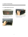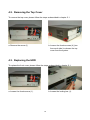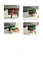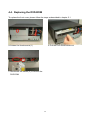
1
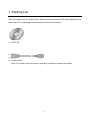
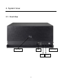
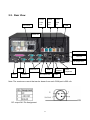
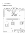
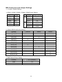
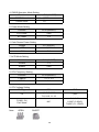
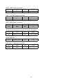
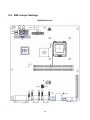
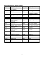
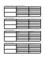
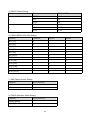
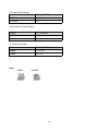
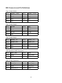
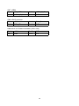
User Manual Revision v1.0 Orion December Copyright 2009 February All Rights Reserved Manual Version 1.0 Part Number: The information contained in this document is subject to change without notice. We make no warranty of any kind with regard to this material, including, but not limited to, the implied warranties of merchantability and fitness for a particular purpose. We shall not be liable for errors contained herein or for incidental or consequential damages in connection with the furnishing, performance, or use of this material. This document contains proprietary information that is protected by copyright. All rights are reserved. No part of this document may be photocopied, reproduced or translated to another language without the prior written consent of the manufacturer. TRADEMARK Intel®, Pentium® and MMX are registered trademarks of Intel® Corporation. Microsoft® and Windows® are registered trademarks of Microsoft Corporation. Other trademarks mentioned herein are the property of their respective owners. 2 Safety IMPORTANT SAFETY INSTRUCTIONS 1. 2. 3. 4. 5. 6. 7. 8. 9. To disconnect the machine from the electrical power supply, turn off the power switch and remove the power cord plug from the wall socket. The wall socket must be easily accessible and in close proximity to the machine. Read these instructions carefully. Save these instructions for future reference. Follow all warnings and instructions marked on the product. Do not use this product near water. Do not place this product on an unstable cart, stand, or table. The product may fall, causing serious damage to the product. Slots and openings in the cabinet and the back or bottom are provided for ventilation to ensure reliable operation of the product and to protect it from overheating. These openings must not be blocked or covered. The openings should never be blocked by placing the product on a bed, sofa, rug, or other similar surface. This product should never be placed near or over a radiator or heat register or in a built-in installation unless proper ventilation is provided. This product should be operated from the type of power indicated on the marking label. If you are not sure of the type of power available, consult your dealer or local power company. Do not allow anything to rest on the power cord. Do not locate this product where persons will walk on the cord. Never push objects of any kind into this product through cabinet slots as they may touch dangerous voltage points or short out parts that could result in a fire or electric shock. Never spill liquid of any kind on the product. CE MARK This device complies with the requirements of the EEC directive 2004/108/EC with regard to “Electromagnetic compatibility” and 2006/95/EC “Low Voltage Directive”. FCC This device complies with part 15 of the FCC rules. Operation is subject to the following two conditions: (1) This device may not cause harmful interference. (2) This device must accept any interference received, including interference that may cause undesired operation. 3 CAUTION ON LITHIUM BATTERIES There is a danger of explosion if the battery is replaced incorrectly. Replace only with the same or equivalent type recommended by the manufacturer. Discard used batteries according to the manufacturer’s instructions. LEGISLATION AND WEEE SYMBOL 2002/96/EC Waste Electrical and Electronic Equipment Directive on the treatment, collection, recycling and disposal of electric and electronic devices and their components. The crossed dustbin symbol on the device means that it should not be disposed of with other household wastes at the end of its working life. Instead, the device should be taken to the waste collection centers for activation of the treatment, collection, recycling and disposal procedure. To prevent possible harm to the environment or human health from uncontrolled waste disposal, please separate this from other types of wastes and recycle it responsibly to promote the sustainable reuse of material resources. Household users should contact either the retailer where they purchased this product, or their local government office, for details of where and how they can take this item for environmentally safe recycling. Business users should contact their supplier and check the terms and conditions of the purchase contract. This product should not be mixed with other commercial wastes for disposal. 4 Revision History Changes to the original user manual are listed below: Version Date 1.0 2009 December Description Initial release 5 Table of Content 1. 2. 3. 4. 5. 6. Packing List ..................................................................................................................7 System View .................................................................................................................8 2.1. Front View............................................................................................................8 2.2. Rear View ............................................................................................................9 Peripherals Installation ...............................................................................................10 3.1. B89 Cash Drawer Installation ............................................................................10 3.2. B99 Cash Drawer Installation ............................................................................12 System Disassembly ..................................................................................................14 4.1. Removing the Front Cover.................................................................................14 4.2. Removing the Top Cover ...................................................................................15 4.3. Replacing the HDD ............................................................................................15 4.4. Replacing the DVD-ROM...................................................................................17 4.5. Replacing the Power Supply..............................................................................18 4.6. Replacing the I/O & PCI Extension Module .......................................................19 4.7. Replacing the Memory.......................................................................................20 4.8. Replacing the Motherboard ...............................................................................20 Specification ...............................................................................................................22 Jumper Settings..........................................................................................................24 6.1. B89 Jumper Settings .........................................................................................24 6.2. B99 Jumper Settings .........................................................................................29 Appendix A: PCI Card Dimension ......................................................................................36 Appendix B: Driver Installation...........................................................................................37 Please insert the Driver CD into the drive and double click on the “index.htm” to select the models. You can refer to the drivers installation guide for each driver in the “Driver/Manual List”. ...................................................................................................................................37 6 1. Packing List Take the system unit out of the carton. Remove the unit from the carton by holding it by the foam inserts. The following contents should be found in the carton: a. Driver CD b. Power Cable Note: The power cord type various according to different country and region. 7 2. System View 2.1. Front View USB Key Lock Power Button HDD 8 Power 2.2. Rear View AC Power Power Power Power USB USB USB 24V 12V 5V USB COM2 & 4 COM 6 Line Out DC Output 24V LPT COM 3 & 5 USB Cash Drawer P/S 2 Keyboard VGA COM1 DC Output 12V LAN Note: The maximum current that can be drawn from each COM port is 500 mA. DC output 24V Pin Assignment 9 3. Peripherals Installation 3.1. B89 Cash Drawer Installation You can install a cash drawer through the cash drawer port. Please verify the pin assignment before installation Cash Drawer Pin Assignment 6 1 Pin Signal 1 GND 2 DOUT bit0 3 DIN bit0 4 12V / 24V 5 DOUT bit1 6 GND Cash Drawer Controller Register The Cash Drawer Controller use one I/O addresses to control the Cash Drawer. Register Location: 4B8h Attribute: Read / Write Size: 8bit BIT BIT7 BIT6 Attribute 7 X 6 X 5 X BIT5 Reserved 4 3 X 2 1 BIT4 BIT3 Read Reserved BIT2 0 X Reserved Cash Drawer “DOUT bit1” pin output control Cash Drawer “DOUT bit0” pin output control Reserved Cash Drawer “DIN bit0” pin input status Reserved 10 BIT1 Write BIT0 Reserved Bit 7: Reserved. Bit 6: Reserved. Bit 5: Reserved. Bit 4: Cash Drawer “DIN bit0” pin input status. = 1: the Cash Drawer closed or no Cash Drawer. = 0: the Cash Drawer opened. Bit 3: Reserved. Bit 2: Cash Drawer “DOUT bit0” pin output control. = 1: Opening the Cash Drawer = 0: Allow closing the Cash Drawer Bit 1: Cash Drawer “DOUT bit1” pin output control. = 1: Opening the Cash Drawer = 0: Allow closing the Cash Drawer Bit 0: Reserved Note: Please follow the Cash Drawer control signal design to control the Cash Drawer Cash Drawer Control Command Example Use Debug.EXE program under DOS or Windows98 Command Cash Drawer O 4B8 04 Opening O 4B8 00 Allow to closing Set the I/O address 4B8h bit2 =1 for opening the Cash Drawer by “DOUT bit0” pin control. Set the I/O address 4B8h bit2 = 0 to allow closing Cash Drawer. Command Cash Drawer I 4B8 Check status The I/O address 4B8h bit4 =1 means the Cash Drawer is closed or no Cash Drawer. The I/O address 4B8h bit4 =0 means the Cash Drawer is open. 11 3.2. B99 Cash Drawer Installation You can install a cash drawer through the cash drawer port. Please verify the pin assignment before installation. Cash Drawer Pin Assignment 6 Pin Signal 1 GND 2 DOUT bit0 3 DIN bit0 4 12V / 24V 5 DOUT bit1 6 GND 1 Cash Drawer Controller Register The Cash Drawer Controller use one I/O addresses to control the Cash Drawer. Register Location: 48Ch Attribute: Read / Write Size: 8bit BIT Attribute 7 X 6 BIT7 BIT6 Reserved 5 4 X X 3 2 1 0 X X BIT5 Read BIT4 Reserved BIT3 BIT2 Write Reserved Cash Drawer “DOUT bit0” pin output control Cash Drawer “DOUT bit1” pin output control Reserved Cash Drawer “DIN bit0” pin output control Reserved 12 BIT1 BIT0 Reserved Bit 7: Reserved Bit 6: Cash Drawer “DIN bit0” pin input status. = 1: the Cash Drawer closed or no Cash Drawer = 0: the Cash Drawer opened Bit 5: Reserved Bit 4: Reserved Bit 3: Cash Drawer “DOUT bit1” pin output control. = 1: Opening the Cash Drawer = 0: Allow close the Cash Drawer Bit 2: Cash Drawer “DOUT bit0” pin output control. = 1: Opening the Cash Drawer = 0: Allow close the Cash Drawer Bit 1: Reserved Bit 0: Reserved Note: Please follow the Cash Drawer control signal design to control the Cash Drawer. Cash Drawer Control Command Example Use Debug.EXE program under DOS or Windows98 Command Cash Drawer O 48C 04 Opening O 48C 00 Allow to close Set the I/O address 48Ch bit2 =1 for opening Cash Drawer by “DOUT bit0” pin control. Set the I/O address 48Ch bit2 = 0 for allow close Cash Drawer. Command Cash Drawer I 48C Check status The I/O address 48Ch bit6 =1 mean the Cash Drawer is opened or not exist. The I/O address 48Ch bit6 =0 mean the Cash Drawer is closed. 13 4. System Disassembly 4.1. Removing the Front Cover a. Use the key to unlock the front cover Remove the front cover b. Lift the front cover up in the direction as shown by the arrows c. Remove the front cover 14 4.2. Removing the Top Cover To remove the top cover, please follow the steps as described in chapter 5.1. a. Remove the screw (1) b. Loosen the thumb screws (4) (two from each side) to release the top cover from the system. 4.3. Replacing the HDD To replace the front cover, please follow the steps as described in chapter 5.1. a. Loosen the thumb screw (1). b. Loosen the locking bar (1). 15 c. Disconnect the cables (4). d. Use your finger to pull the HDD holder out. e. Remove the HDD. f. Repeat the step d. and e. to remove the other HDD. 16 4.4. Replacing the DVD-ROM To replace the front cover, please follow the steps as described in chapter 5.1 a. Loosen the thumb screw (1) b. Pull the DVD-ROM holder out c. Disconnect the cables (2) to remove the DVD-ROM 17 4.5. Replacing the Power Supply To replace the power supply, please follow the steps as described in chapter 5.1 and 5.2 d. Remove the screw (1) and slide the e. Disconnect the cables (3) to release the power supply holder in the direction as power supply holder from the system. shown by the arrow. f. Remove the screws (3) to separate the power supply from the holder. 18 4.6. Replacing the I/O & PCI Extension Module To replace the I/O and PCI extension module, please follow the steps as described in chapter 5.1 and 5.2 a. Remove the extension module by gently pulling it upwards taking care not to damage the connector. b. Disconnect the cables (3) and remove the I/O module from the holder. c. Disconnect the cables (2) and remove the screws (2) to release the PCI riser card from the holder. 19 4.7. Replacing the Memory To replace the memory, please follow the steps as described in chapter 5.1, 5.2, 5.5(a) a. Use your finger to push the DIMM slot ejector clips into the down position. b. Remove the memory module from the slot. 4.8. Replacing the Motherboard To replace the motherboard, please follow the steps as described in chapter 5.1, 5.2, 5.5(a) and 5.6(a) a. Disconnect the cables (2), remove the screws (2) and slide the HDD module in the direction as shown by the arrows to release the module from the motherboard Chassis b. Remove the screw (1) and disconnect the cables (9) as shown in the picture. 20 c. Remove the screws (7) d. Remove the hex screws (14) to release the motherboard from the chassis 21 5. Specification Mainboard CPU Support Chipset System Memory Graphic Memory B89 B99 Intel SK478 CPU Up to P4 2.6G, Intel P4 / Celeron / Core 2 Duo Celeron 2.5G, Mobile Celeron LGA775 1.2G INTEL 945G FSB 533 / 800 / INTEL 852GM + ICH4 1066 MHz + ICH7R Up to 4GB DDR ll RAM, Up to 2GB DDR RAM, 2 RAM-DIMM 2 RAM-DIMM Shared memory up to 232MB Shared memory up to 64MB Storage HDD ODD 2 x 3.5" SATA 2 x 3.5" PATA 1 x Slim PATA CD-ROM / CD-RW / DVD-ROM Drive Bay (optional) Expansion PCI Slot 2 slots supported from PCI riser card External I/O Ports Front I/O USB 2 ( USB1~2 ) 1 (USB 7) 10 / 100 / 1000 Mb 10 / 100Mb Rear I/O LAN PS/2 Keyboard 1 USB Power Serial RS232 4 ( USB3~ 6 ) 5 ( COM1, COM2, COM3, COM4, COM5 ) Serial RS232/422/485 1 ( COM6 ) Parallel 1 VGA 1 ( DB15 ) Line- out 1 Cash Drawer Port 1 DC 24V output 1 DC 12V output 1 22 Control / Indicators Power Button 1 (Front) LED_HDD/Power 2 Internal Header USB 1 ( USB8 ) Power Button 1 ( pin header) Peripherals (special feature) 80GB (optional) N/A Supports RAID 0, RAID 1 for 2 SATA HDDs N/A Second HDD (hot swap) RAID Built-in System ID Option Module ( Connectivity) Powered USB (12V) 2 Powered USB (24V) 1 Powered USB (5V) 1 USB 4 Environment EMC & Safety Operating Temperature Storage Temperature FCC Class A, CE, LVD 5°C~ 35°C (41°F ~95°F) -10°C~ 60°C (14°F ~140°F) Operating Humidity 20% - 85% RH non condensing Storage Humidity 5% - 90% RH non condensing Dimension (W x D x H) System Box 270 x 300 x 120mm 230W Power Supply 23 6. Jumper Settings 6.1. B89 Jumper Settings B89 Motherboard 24 B89 Connectors and Jumper Settings ◎ = Factory Default Setting 1. COM1 / COM2 / COM3 / COM4 / COM5 Power Setting COM Port Jumper COM1 JP4 COM2 JP8 COM3 Pin Function Jumper Setting ◎1-2 DCD# 1 +5V 3-4 JP6 +12V 5-6 COM4 JP5 RI# ◎7-8 COM5 JP3 +5V 9-10 +12V 11-12 9 2. COM 6 RS232/ 485/ 422 Setting Function ◎RS232 JP9 (1-2) v JP9 (3-4) v RS485 JP9 (4-6) JP9 (5-7) v v JP9 (7-8) v JP9 (9-10) JP10 (1-2) RS422 v v v JP10 (3-4) JP10 (5-6) v JP10 (7-8) v JP10 (9-10) v JP10 (11-12) v 3. 2ND Display Power Setting Function JP11 (SHORT) +12V 1-2 NC ◎1 25 4. CMOS Operation Mode Setting Function JP13 (SHORT) ◎N/C COMS Normal COMS Reset 1-2 5. Power Mode Setting Function JP15 (SHORT) ATX Power ◎N/C AT Power 1-2 6. Cash Drawer Power Setting Voltage JP7 (SHORT) +12V ◎1-2 + 24V 3-4 7. ACPI Mode Setting Function JP12 (SHORT) Disable 1-2 Enable ◎N/C 8. CPU Frequency Setting Function JP14 (SHORT) FSB400 ◎1-2, 3-4 FSB533 3-4 9. CPU Voltage Setting CPU Type JP16 JP17 P4 ◎1-2, 3-4, 5-6 7-8, 9-10, 11-12 ◎N/C N/C 3-4, 9-10 1-2(NC), 5-6(NC) 7-8(NC), 11-12(NC) P4-M(1.3V) Perf. Mode Note: OPEN SHORT 26 B89 Connector and Pin Definitions CN4: COM6 RS232/422/485 Pin 1 DB9_1 Pin 2 DB9_2 Pin 3 DB9_3 Pin 4 DB9_4 Pin 5 GND Pin 6 RS232_6_DSR# Pin 7 RS232_6_RTS# Pin 8 RS232_6_CTS# Pin9 RS232_6_RI Pin 10 N/C CN6: Speaker & MIC Connector Pin 1 LIN_OUT_L Pin 2 GND Pin 3 GND Pin 4 LIN_OUT_R Pin 5 GND Pin 6 MIC1 CN7: CD-IN & Line-In Connector Pin 1 CDIN_L Pin 2 CDIN_REF Pin 3 CDIN_R Pin 4 CDIN_REF Pin 5 GND Pin 6 LINE_IN_L Pin 7 LINE_IN_R Pin 8 GND GND Pin 2 PWR_OK Pin 1 +5V_USB1 Pin 2 USB20_R_P1- Pin 3 USB20_R_P1 + Pin 4 GND CN8: Hardware Reset Pin 1 CN10: USB5 CN12: Power LED Pin 1 +5V Pin 2 GND Pin 2 SW_PWRBT# CN13: Power Button Pin 1 GND 27 CN15: HDD Power Connector Pin 1 +12V Pin 2 GND Pin 3 GND Pin 4 +5V CN16: CD-ROM Power Connector Pin 1 +12V Pin 2 GND Pin 3 GND Pin 4 +5V CN17: HDD Power Connector Pin 1 +12V Pin 2 GND Pin 3 GND Pin 4 +5V CN18: Power Connector external 12V Power connector Pin 1 +12V Pin 2 GND Pin 3 GND (not used) Pin 4 +5V (not used) Pin 2 +5V CN19: IDE LED Pin 1 HDD_LED# FAN_CPU3: CPU FAN CONTROL Pin 1 GND Pin 3 FB Pin 2 +12V 28 6.2. B99 Jumper Settings B99 Motherboard 29 B99 Connectors and Jumper Settings Connectors Function Connectors Function BAT3 CMOS Battery Base ( use CR2023) FAN_CPU3 CPU Fan Connector CN3 LAN & USB5/ USB6 FAN_SYS3 System Fan Connector CN4 COM6 Connector IDE3 Primary IDE Connector (40pin pitch = 2.54mm) CN5 Speaker & MIC Connector PCI3 PCI Slot CN6 CD-in & Line-in Connector PRN3 Parallel Port CN7 USB8 PS3 PS2 Connector CN8 IrDA Connector PWR3 +24V Power Output CN9 Power Connector (+5V/+12V) PWR4 ATX Power Connector CN10 Power Connector (+5V/+12V) PWR5 VRM +12V Connector CN11 Hardware Reset Connector RJ11_3 Cash drawer Connector CN12 Power Connector (+5V/+12V) SATA1 Serial ATA CN13 Power Connector (+5V/+12V) SATA2 Serial ATA CN14 Internal Power Switch Connector SATA3 Serial ATA CN15 Power LED Connector SATA4 Serial ATA CN16 HDD Action LED Connector USB3 USB3/USB4 CN17 LAN Action LED Connector USB4 USB1 COM1_3 COM4/COM5 USB5 USB2 COM3_3 COM2/COM3 VGA3 VGA Port COM3 COM1 30 1. COM1 Power Setting ◎Factory Default Setting Pin 1 9 Function JP4 (SHORT) DCD# ◎1-2 +5V 3-4 +12V 5-6 RI# ◎7-8 +5V 9-10 +12V 11-12 Function JP8 (SHORT) DCD# ◎1-2 +5V 3-4 +12V 5-6 RI# ◎7-8 +5V 9-10 +12V 11-12 Function JP6 (SHORT) DCD# ◎1-2 +5V 3-4 +12V 5-6 RI# ◎7-8 +5V 9-10 +12V 11-12 Function JP5 (SHORT) DCD# ◎1-2 +5V 3-4 +12V 5-6 RI# ◎7-8 +5V 9-10 +12V 11-12 2. COM 2 Power Setting Pin 1 9 3. COM 3 Power Setting Pin 1 9 4. COM 4 Power Setting Pin 1 9 31 5. COM 5 Power Setting Pin 1 9 Function JP3 (SHORT) DCD# ◎1-2 +5V 3-4 +12V 5-6 RI# ◎7-8 +5V 9-10 +12V 11-12 6. COM 6 RS232/ 422/ 485 Setting Function ◎RS232 JP9 (1-2) v JP9 (3-4) v RS422 JP9 (4-6) JP9 (5-7) v v JP9 (7-8) v JP9 (9-10) JP10 (1-2) RS485 v v v JP10 (3-4) JP10 (5-6) v JP10 (7-8) v JP10 (9-10) v JP10 (11-12) v 7. 2ND Display Power Setting Function JP11 (SHORT) +12V 1-2 NC ◎1 8. CMOS Operation Mode Setting Function JP13 (SHORT) COMS Normal ◎N/C COMS Reset 1-2 32 9. Power Mode Setting Function JP14 (SHORT) ATX Power ◎N/C AT Power 1-2 Cash Drawer Power Setting Voltage JP7 (SHORT) +12V ◎1-2 + 24V 3-4 11. System Indicator Function JP15 (SHORT) Disable ◎1-2 3-4 Enable 5-6 7-8 Note: OPEN SHORT 33 B99 Connector and Pin Definitions CN4: COM6 RS232 Pin 1 RS485_TXRX- Pin 2 RS485_TXRX+ Pin 3 N/C Pin 4 N/C Pin 5 GND Pin 6 N/C Pin 7 N/C Pin 8 N/C Pin 9 N/C CN4: COM6 RS485 Pin 1 DCD# Pin 2 Rx# Pin 3 Tx# Pin 4 DTR# Pin 5 GND Pin 6 DSR# Pin 7 RTS# Pin 8 CTS# Pin 9 RI# CN4: COM6 RS422 Pin 1 RS422_TX- Pin 2 RS422_TX+ Pin 3 RS422_RX+ Pin 4 RS422_RX- Pin 5 GND Pin 6 N/C Pin 7 N/C Pin 8 N/C Pin9 N/C CN5: Speaker & MIC Connector Pin 1 AMP_ORL Pin 2 GND Pin 3 GND Pin 4 AMP_ORR Pin 5 GND Pin 6 MIC1 CN6: CD-IN Connector Pin 1 CDIN_L Pin 2 CDIN_REF Pin 3 CDIN_R Pin 4 CDIN_REF Pin 5 GND Pin 6 LINE_IN_L Pin 7 LINE_IN_R Pin 8 GND 34 CN7: USB8 Pin 1 +5V_USB1 Pin 2 USB20_R_P1 Pin 3 USB20_R_P1+ Pin 4 GND CN8: IrDA Connector Pin 1 +5V Pin 2 IRDA_RX Pin 3 IRDA_TX Pin 4 GND CN9/10/12/13: Power Connector (+5V/+12V) Pin 1 +12V Pin 2 GND Pin 3 GND Pin 4 +5V 35 Appendix A: PCI Card Dimension Maximum dimension of the PCI add-on card: Component Side: 130mm x 90.26mm ( D x W ) (Picture 1) 36 Appendix B: Driver Installation The shipping package includes a Driver CD in which you can find every individual driver and utility that enables you to install the drivers on the system. Please insert the Driver CD into the drive and double click on the “index.htm” to select the models. You can refer to the drivers installation guide for each driver in the “Driver/Manual List”. 37