1
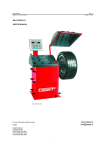
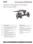
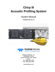
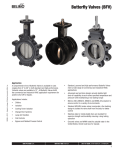
Sizing/Selection Characterized Control Valves™ (CCV) K20903 - 04/08 - Subject to change. © Belimo Aircontrols (USA), Inc. 2-Way Valve Flow Rate for Water Applications (Gallons Per Minute, GPM) Cv Maximum Rating Inches DN mm 2-Way CCV Pressure Drop Across the Valve 1 psi 2 psi 3 psi 4 psi 5 psi 6 psi 7 psi 8 psi 9 psi 10 psi 0.3 0.46 0.8 1.2 1.9 3 4.7 7.4 10 4.7 7.4 10 24 7.4 10 19 30 10 19 25 37 19 29 37 29 46 57 65 85 120 240 60 75 110 150 210 70 130 170 60 75 110 150 210 70 130 170 ½” ½” ½” ½” ½” ½” ½” ½” ½” ¾” ¾” ¾” ¾” 1” 1” 1” 1” 1¼” 1¼” 1¼” 1¼” 1½”” 1½” 1½” 2” 2” 2” 2” 2” 2” 2” 2½” 2½” 2½” 2½” 2½” 3” 3” 3” 2½” 2½” 2½” 2½” 2½” 3” 3” 3” 15 15 15 15 15 15 15 15 15 20 20 20 20 25 25 25 25 32 32 32 32 40 40 40 50 50 50 50 50 50 50 65 65 65 65 65 80 80 80 65 65 65 65 65 80 80 80 B207(B) B208(B) B209(B) B210(B) B211(B) B212(B) B213(B) B214(B) B215(B)* B217(B) B218(B) B219(B) B220(B)* B222 B223 B224 B225* B229 B230* B231 B232* B238 B239 B240* B248 B249 B250* B251 B252 B253 B254* B261 B262 B263 B264 B265* B277 B278 B280* B661 B662 B663 B664 B665* B677 B678 B680* 0.3 0.5 0.8 1.2 1.9 3.0 4.7 7.4 10 4.7 7.4 10 24 7.4 10 19 30 10 19 25 37 19 29 37 29 46 57 65 85 120 240 60 75 110 150 210 70 130 170 60 75 110 150 210 70 130 170 0.4 0.7 1.1 1.7 2.7 4.2 6.6 10 14 6.6 10 14 34 10 14 27 42 14 27 35 52 27 41 52 41 65 81 92 120 170 339 85 106 156 212 297 99 194 240 85 106 156 212 297 99 194 240 0.5 0.8 1.4 2.1 3.3 5.2 8.1 13 17 8.1 13 17 42 13 17 33 52 17 33 43 64 33 50 64 50 80 99 113 147 208 416 104 130 191 260 364 121 225 294 104 130 191 260 364 121 225 294 0.6 0.9 1.6 2.4 3.8 6.0 9.4 15 20 9.4 15 20 48 15 20 38 60 20 38 50 74 38 58 74 58 92 114 130 170 240 480 120 150 220 300 420 140 260 340 120 150 220 300 420 140 260 340 0.7 1.0 1.8 2.8 4.2 6.8 11 17 22 11 17 22 54 17 22 42 67 22 42 56 83 42 65 83 65 103 127 145 190 268 537 134 168 246 335 470 157 290 380 134 168 246 335 470 157 290 380 0.7 1.1 2.0 2.9 4.7 7.3 12 18 24 12 18 24 59 18 24 47 73 24 47 61 91 47 71 91 71 113 140 159 208 294 588 147 194 269 367 514 172 318 416 147 194 269 367 514 172 318 416 0.8 1.2 2.1 3.2 5.0 7.9 12 20 26 12 20 26 63 20 26 50 79 26 50 66 98 50 77 98 77 122 151 170 225 318 635 159 198 291 397 556 185 344 450 159 198 291 397 556 185 344 450 0.8 1.3 2.3 3.4 5.4 8.5 13 21 28 13 21 28 68 21 28 54 85 28 54 71 105 54 82 105 82 130 161 194 240 339 679 170 212 311 424 594 198 368 481 170 212 311 424 594 198 368 481 0.9 1.4 2.4 3.6 5.7 9.0 14 22 30 14 22 30 72 22 30 57 90 30 57 75 111 57 87 111 87 138 171 195 255 360 720 180 225 330 450 630 210 390 510 180 225 330 450 630 210 390 510 0.9 1.5 2.5 3.8 6.0 9.5 15 23 32 15 23 32 76 23 32 60 95 32 60 79 117 60 92 117 92 145 180 206 269 380 759 190 237 348 474 664 221 411 538 190 237 348 474 664 221 411 538 GPM = Cv x ∆p * = Models with no characterizing disc. The influence of the pipe geometry due to reduced flow is negligible for all valves 57 Cv and below with characterizing discs. 800-543-9038 USA 866-805-7089 Canada 203-791-8396 Latin America 3 Sizing/Selection Characterized Control Valves™ (CCV) 3-Way Valve Flow Rate for Water Applications (Gallons Per Minute, GPM) Cv Maximum Rating Inches DN mm 3-Way CCV Pressure Drop Across the Valve 1 psi 2 psi 3 psi 4 psi 5 psi 6 psi 7 psi 8 psi 9 psi 10 psi 0.3 0.46 0.8 1.2 1.9 3 4.7 10 4.7 7.4 24 7.4 10 30 10 19 25 19 29 37 46 29 37 46 57 68 83 ½” ½” ½” ½” ½” ½” ½” ½” ¾” ¾” ¾” 1” 1” 1” 1¼” 1¼” 1¼” 1½” 1½” 1½” 1½” 2” 2” 2” 2” 2” 2” 15 15 15 15 15 15 15 15 20 20 20 25 25 25 32 32 32 40 40 40 40 50 50 50 50 50 50 B307(B) B308(B) B309(B) B310(B) B311(B) B312(B) B313(B) B315(B)* B317(B) B318(B) B320(B)* B322 B323 B325* B329 B330 B331 B338 B339 B340 B341 B347 B348 B349 B350 B351 B352 0.3 0.5 0.8 1.2 1.9 3.0 4.7 10 4.7 7.4 24 7.4 10 30 10 19 25 19 29 37 46 29 37 46 57 68 83 0.4 0.7 1.1 1.7 2.7 4.2 6.6 14 6.6 10 34 10 14 42 14 27 35 27 41 52 65 41 52 65 81 96 117 0.5 0.8 1.4 2.1 3.3 5.2 8.1 17 8.1 13 42 13 17 52 17 33 43 33 50 64 80 50 64 80 99 118 144 0.6 0.9 1.6 2.4 3.8 6.0 9.4 20 9.4 15 48 15 20 60 20 38 50 38 58 74 92 58 74 92 114 136 166 0.7 1.0 1.8 2.8 4.2 6.8 11 22 11 17 54 17 22 67 22 43 56 43 65 83 103 65 83 103 128 152 186 0.7 1.1 2.0 2.9 4.7 7.3 12 24 12 18 59 18 24 73 25 47 61 47 71 91 113 71 91 113 140 167 204 0.8 1.2 2.1 3.2 5.0 7.9 12 26 12 20 63 20 26 79 27 50 66 50 77 98 122 77 98 122 151 180 220 0.8 1.3 2.3 3.4 5.4 8.5 13 28 13 21 68 21 28 85 28 54 71 54 82 105 130 82 105 130 161 192 235 0.9 1.4 2.4 3.6 5.7 9.0 14 30 14 22 72 22 30 90 30 57 75 57 87 111 138 87 111 138 171 204 249 0.9 1.5 2.5 3.8 6.0 9.5 15 32 15 23 76 23 32 95 32 60 79 60 92 117 146 92 117 146 180 215 263 K20903 - 04/08 - Subject to change. © Belimo Aircontrols (USA), Inc. GPM = Cv x ∆p * = Models with no characterizing disc. The influence of the pipe geometry due to reduced flow is negligible for all valves 83 Cv and below with characterizing discs. 800-543-9038 USA 4 866-805-7089 Canada 203-791-8396 Latin America Set-up and Wiring Instructions Characterized Control Valves™ (CCV) Set-Up 2-way Valve Specify upon ordering TR24-3-T US TR24-3 US Power to pin 2 will drive valve CCW. Power to pin 3 will drive valve CW. Stays in Last Position Non-Spring Return On/Off or Floating Point Actuators Note Fail Position Spring Return Power to pin 2 will drive valve CCW. Power to pin 3 will drive valve CW. TR24-SR-T US TR24-SR US NC: Closed A to AB, will open as voltage increases. NO: Open A to AB, will close as voltage increases. (Can be chosen with switch inside terminal block of actuator.) NC: Closed A to AB, will open as voltage increases. NO: Open A to AB, will close as voltage increases. (Can be chosen with switch inside terminal block of actuator.) LRB24 (-3), MFT, SR LRX24 (-3), MFT, SR ARB24 (-3), MFT, SR ARX24 (-3), MFT, SR Power to pin 2 will drive valve CW. Power to pin 3 will drive valve CCW. The above will function when the directional switch is in the “1” position, to reverse select the “0” position. NO: Open A to AB, will close as voltage increases or power applied. (Can be chosen with CW/CCW switch.) Power to pin 2 will drive valve CW. Power to pin 3 will drive valve CCW. The above will function when the directional switch is in the “1” position, to reverse select the “0” position. NO: Open A to AB, will close as voltage increases or power applied. (Can be chosen with CW/CCW switch.) TFX24 US LF24 US AF24 US NO/FO Valve: Open A to AB will drive closed. Spring Action: Will spring open A to AB upon power loss. NC/FC Valve: Closed A to AB will drive open. Spring Action: Will spring closed A to AB upon power loss. NO/FO Valve: Open A to AB will drive closed. Spring Action: Will spring open A to AB upon power loss. NC/FC Valve: Closed A to AB will drive open. Spring Action: Will spring closed A to AB upon power loss. TF (-3), MFT, SR LF (-3), MFT, SR AF (-3), MFT, SR NC/FO Valve: Closed A to AB will drive open. Spring Action: Will spring open A to AB upon power loss. NC/FC or NO/FC Valve: Closed A to AB or Open A to AB. (Can be chosen with CW/CCW switch.) Spring Action: Will spring closed A to AB upon power loss. NC/FO Valve: Closed A to AB will drive open Spring Action: Will spring open A to AB upon power loss. NC/FC or NO/FC Valve: Closed A to AB or Open A to AB. (Can be chosen with CW/CCW switch.) Spring Action: Will spring closed A to AB upon power loss. Proportional Type Actuators Floating Point or Proportional Type Actuators K20903 - 04/08 - Subject to change. © Belimo Aircontrols (USA), Inc. 3-way Valve Specify upon ordering Floating Point or Proportional Type Actuators NO/FO Valve: Open A to AB Spring Action: Will spring open A to AB upon power loss. (NO action can be chosen with CW/CCW switch.) NO/FO Valve: Open A to AB Spring Action: Will spring open A to AB upon power loss. (NO action can be chosen with CW/CCW switch.) General Wiring Instructions WARNING The wiring technician must be trained and experienced with electronic circuits. Disconnect power supply before attempting any wiring connections or changes. Make all connections in accordance with wiring diagrams and follow all applicable local and national codes. Provide disconnect and overload protection as required. Use copper, twisted pair, conductors only. If using electrical conduit, the attachment to the actuator must be made with flexible conduit. Always read the controller manufacturer's installation literature carefully before making any connections. Follow all instructions in this literature. If you have any questions, contact the controller manufacturer and/or Belimo. Transformer(s) Belimo actuators require a 24 VAC class 2 transformer and draws a maximum of 10 VA per actuator. The actuator enclosure cannot be opened in the field, there are no parts or components to be replaced or repaired. 800-543-9038 USA – EMC directive: 89/336/EEC – Software class A: Mode of operation type 1 – Low voltage directive: 73/23/EEC CAUTION It is good practice to power electronic or digital controllers from a separate power transformer than that used for actuators or other end devices. The power supply design in our actuators and other end devices use half wave rectification. Some controllers use full wave rectification. When these two different types of power supplies are connected to the same power transformer and the DC commons are connected together, a short circuit is created across one of the diodes in the full wave power supply, damaging the controller. Only use a single power transformer to power the controller and actuator if you know the controller power supply uses half wave rectification. 866-805-7089 Canada 203-791-8396 Latin America 5 Flow, Operation and Installation Characterized Control Valves™ (CCV) Flow Patterns 2-way Characterized Control Valves™ (Belimo B2 Series) (Belimo B6 Series) Flow direction Two-way valves should be installed with the disc upstream. 3-way Characterized Control Valves™ MIXING (Belimo B3 Series) DIVERTING The A-port must be piped to the coil to maintain proper control. Incorrect Piping The A-port must be piped to the coil to maintain proper control. B Coil Coil A B AB Three-Way Diverting Diagram Three-Way Diverting Valve Valve PipingPiping Diagram (1 Input, 2 Outputs) (1 Input, 2 Outputs) A ReturnReturn ReturnReturn AB Coil Coil A A SupplySupply SupplySupply B B AB AB WARNING! Do Not Pipe in this manner! Note Valve Porting! The A-port must be piped to the coil! Not the B-port! Flow is not possible from A to B. If AB-port is not piped as the common port, the valve must be re-piped. It is good practice to install a balancingvalve in the bypass line. These valves are intended for closed loop systems. Do not install in an open loop system or in an application that is open to atmospheric pressure. Operation/Installation – Correct Piping 2-way valves should be installed with the disc upstream. If installed with disc downstream, flow curve will be deeper. If installed “backwards” it is NOT necessary to remove and change. No damage or control problems will occur. 3-way valves must be piped correctly. They can be mixing or diverting. Mixing is the preferred piping arrangement. The BELIMO Characterized Control Valve is a CONTROL valve, not a manual valve adapted for actuation. The control port is the A-port. It is similar to the globe valve in that the middle port is the B or bypass port. The common port AB is on the main opposite the A-port. These diagrams are for typical applications only. Consult engineering specification and drawings for particular circumstances. Reduced B-Port Flow Note: The B-port flow of the 3-way CCV is lower than that of the A-port. In most applications this is beneficial since the reduced flow compensates for the inexistent pressure drop across the coil in the bypass mode. Therefore, proper sizing is important to avoid flow noise in particular when the system is designed with constant speed pumps. Please refer to our valve sizing and selection guidelines. The flow velocity in the pipe upstream and downstream of the valve should be considered as well. The typical HVAC design maximum flow is 4 to 8 ft/s to avoid noise issues. Also, the pipe reduction factor must be considered and can be found on pages 3 and 4. Pipe reducers decrease the Cv value of a valve and consequently increase the pressure drop across the valve, a situation that could lead to noise or a lower than designed flow. 800-543-9038 USA 6 866-805-7089 Canada 203-791-8396 Latin America K20903 - 04/08 - Subject to change. © Belimo Aircontrols (USA), Inc. Three-Way Mixing Diagram Three-Way Mixing Valve Valve PipingPiping Diagram (2 Inputs, 1 Output) (2 Inputs, 1 Output)