1
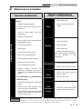
CFX-CHX-USER Rev B User’s Information Manual Models: 402 - 2072 WARNING If the information in this manual is not followed exactly, a fire or explosion may result causing property damage, personal injury or loss of life. This appliance MUST NOT be installed in any location where gasoline or flammable vapors are likely to be present. WHAT TO DO IF YOU SMELL GAS • Do not try to light any appliance. • Do not touch any electric switch; do not use any phone in your building. • Immediately call your gas supplier from a near by phone. Follow the gas supplier’s instructions. • If you cannot reach your gas supplier, call the fire department. • Installation and service must be performed by a qualified installer, service agency, or the gas supplier. Save this manual for future reference. Contents HAZARD DEFINITIONS .................................................... PLEASE READ BEFORE PROCEEDING ........................ 1. PREVENT COMBUSTION AIR CONTAMINATION..... 2. MAINTENANCE SCHEDULE ....................................... Maintenance Procedures ................................................... Appliance Must Be Serviced and Maintained .............. Check Appliance Area .................................................. Check Pressure Temperature Gauge........................... Check Vent Piping ........................................................ Check Air Piping ........................................................... Check Relief Valve ....................................................... Test Low Water Cutoff (if installed) .............................. Reset Button (low water cutoff) .................................... Check Appliance Piping (gas and water) ..................... Operate Relief Valve .................................................... Shut Appliance Down ................................................... 2 3 4 5 6 6 6 6 6 6 6 7 7 7 7 7 3. OPERATING INSTRUCTIONS ..................................... 8 4. SMART SYSTEM CONTROL MODULE Copper-fin II Control Module .............................................. 9 Access Modes .................................................................. 10 Saving Parameters ........................................................... 10 Viewable and Changeable Control Parameters .......... 10-12 Status Display Screens ............................................... 13-15 Revision Notes .................................................. Back Cover Hazard definitions The following defined terms are used throughout this manual to bring attention to the presence of hazards of various risk levels or to important information concerning the life of the product. DANGER DANGER indicates an imminently hazardous situation which, if not avoided, will result in death or serious injury. WARNING indicates a potentially hazardous situation which, if not avoided, could result in death or serious WARNING injury. CAUTION indicates a potentially hazardous situation which, if not avoided, may result in minor or moderate CAUTION injury. CAUTION CAUTION used without the safety alert symbol indicates a potentially hazardous situation which, if not avoided, may result in property damage. NOTICE NOTICE indicates special instructions on installation, operation, or maintenance that are important but not related to personal injury or property damage. 2 User’s Information Manual Please read before proceeding NOTICE WARNING This is a gas appliance and should be installed by a licensed electrician and/or certified gas supplier. Service must be performed by a qualified service installer, service agency or the gas supplier. If the information in these instructions is not followed exactly, a fire or explosion may result causing property damage, personal injury, or death. This appliance MUST NOT be installed in any location where gasoline or flammable vapors are likely to be present, unless the installation is such to eliminate the probable ignition of gasoline or flammable vapors. What to do if you smell gas – • Do not try to light any appliance. • Do not touch any electric switch; do not use any phone in your building. • Immediately call your gas supplier from a neighbors phone. Follow the gas supplier’s instructions. WARNING Checking equipment – Upon receiving equipment, check for signs of shipping damage. Pay particular attention to parts accompanying the appliance which may show signs of being hit or otherwise being mishandled. Verify total number of pieces shown on the packing slip with those actually received. In case there is damage or a shortage, immediately notify the carrier. Do not use this appliance if any part has been under water. The possible damage to a flooded appliance can be extensive and present numerous safety hazards. Any appliance that has been under water must be replaced. Owner warning – The information contained in this manual is intended for use by qualified professional installers, service technicians, or gas suppliers. Consult your local expert for proper installation or service procedures. NOTICE • If you cannot reach your gas supplier, call the fire department. Installation and service must be performed by a qualified installer, service agency, or the gas supplier. Warranty – Factory warranty (shipped with unit) does not apply to units improperly installed or improperly operated. Experience has shown that improper installation or system design, rather than faulty equipment, is the cause of most operating problems. 1. 2. Excessive water hardness causing a lime/scale build-up in the copper tube is not the fault of the equipment and is not covered under the manufacturer’s warranty (see Water Treatment and Water Chemistry in the Copper-fin II Installation and Operation Manual). Excessive pitting and erosion on the inside of the copper tube may be caused by too much water velocity through the tubes and is not covered by the manufacturer’s warranty (see Boiler Flow Rates and Temperature Rise for flow requirements in the Copper-fin II Installation and Operation Manual). Improper installation, adjustment, alteration, service or maintenance can cause injury or property damage. Refer to this manual for assistance or additional information, consult a qualified installer, service agency or the gas supplier. Consult and follow all local Building and Fire Regulations and other Safety Codes that apply to this installation. Consult a local gas utility company to authorize and inspect all gas and flue connections. Your conventionally vented gas appliance must have a supply of fresh air circulating around it during burner operation for proper gas combustion and proper venting. WARNING Should overheating occur or the gas supply fail to shut off, do not turn off or disconnect the electrical supply to the pump. Instead, turn off the manual gas control valve to the appliance at a location external to the appliance. Prevention of freezing – Heat exchangers and headers damaged by freezing are not covered by warranty. See Section 6, Startup - Freeze Protection in the Copper-fin II Installation and Operation for more information. 3 User’s Information Manual 1 Prevent combustion air contamination WARNING WARNING If the boiler combustion air inlet is located in any area likely to cause contamination, or if products which would contaminate the air cannot be removed, you must have the combustion air and vent re-piped and terminated to another location. Contaminated combustion air will damage the boiler, resulting in possible severe personal injury, death, or substantial property damage. If the boiler combustion air inlet is located in a laundry room or pool facility, for example, these areas will always contain hazardous contaminants. Pool and laundry products and common household and hobby products often contain fluorine or chlorine compounds. When these chemicals pass through the boiler, they can form strong acids. The acid can eat through the boiler wall, causing serious damage and presenting a possible threat of flue gas spillage or boiler water leakage into the building. Please read the information listed in Table 1A. If contaminating chemicals will be present near the location of the boiler combustion air inlet, have your installer pipe the boiler combustion air and vent to another location, per the Copper-fin II Installation and Operation Manual. Table 1A Corrosive Contaminants and Sources Products to avoid: Spray cans containing chloro/fluorocarbons Permanent wave solutions Chlorinated waxes/cleaners Chlorine-based swimming pool chemicals Calcium chloride used for thawing Sodium chloride used for water softening Refrigerant leaks Paint or varnish removers Hydrochloric acid/muriatic acid Cements and glues Antistatic fabric softeners used in clothes dryers Chlorine-type bleaches, detergents, and cleaning solvents found in household laundry rooms Adhesives used to fasten building products and other similar products Areas likely to have contaminants Dry cleaning/laundry areas and establishments To prevent the potential of severe WARNING personal injury or death, check for areas and products listed in Table 1A before installing the boiler or air inlet piping. Swimming pools Metal fabrication plants Beauty shops If contaminants are found, you MUST: • Remove contaminants permanently. —OR— • Relocate air inlet and vent terminations to other areas. Refrigeration repair shops Photo processing plants Auto body shops Plastic manufacturing plants Furniture refinishing areas and establishments New building construction Remodeling areas Garages with workshops 4 User’s Information Manual 2 Maintenance schedule Service technician Owner maintenance (see pages 6 - 7 for detailed instructions) • Check boiler area General: • Address reported problems • Inspect interior; clean and vacuum if necessary; Daily • Check pressure/temperature gauge • Check for leaks (water, gas, flue, condensate) • Examine venting system ANNUAL START-UP • Check system water pressure/system piping/expansion tank • Check control settings • Check vent piping Monthly • Check air piping • Check relief valve • Check igniter • Replace combustion air filter Note: More frequent replacement may be necessary in dirty environments. • Check wiring and connections • Check flue gas passageways • Flame inspection (stable, uniform) • Inspect and clean the burner Periodically • Test low water cutoff (if used) • Check manifold gas pressure • Reset button (low water cutoff) • Perform start-up checkout and performance verification per Section 6 in the Copper-fin II Installation and Operation Manual If combustion or performance indicate need: • Check boiler piping (gas and water) for leaks Every 6 months • Operate relief valve • Clean heat exchanger with a stiff bristle brush • Remove and clean burners using water. Dry before re-assembling. • Clean the blower wheel with a brush and vacuum. Do not let dirt from cleaning get pulled into the blower. WARNING End of season months • Shut boiler down (unless boiler used for domestic hot water) Follow the maintenance procedures given throughout this manual. Failure to perform the service and maintenance or follow the directions in this manual could result in damage to the boiler or system, resulting in severe personal injury, death, or substantial property damage. 5 User’s Information Manual 2 Maintenance schedule Maintenance procedures Check vent piping Appliance must be serviced and maintained 1. WARNING NOTICE The appliance must be inspected and started annually at the beginning of the heating season by a qualified service technician. In addition, the maintenance and care of the appliance designated on page 5 of this manual and explained on pages 6 and 7 must be performed to assure maximum appliance efficiency and reliability. Failure to service and maintain the appliance and system could result in equipment failure, causing possible severe personal injury, death, or substantial property damage. The following information provides detailed instructions for completing the maintenance items listed in the maintenance schedule on page 5. In addition to this maintenance, the appliance must be serviced and started up at the beginning of each heating season by a qualified service technician. WARNING To prevent potential of severe personal injury, death, or substantial property damage, eliminate all materials discussed below from the boiler/water heater vicinity and the vicinity of the boiler/water heater combustion air inlet. If contaminants are found: Remove products immediately from the area. If they have been there for an extended period, call a qualified service technician to inspect the appliance for possible damage from acid corrosion. If products cannot be removed, immediately call a qualified service technician to re-pipe vent and air piping and locate vent termination/air intake away from contaminated areas. 1. 2. Combustible/flammable materials -- Do not store combustible materials, gasoline or any other flammable vapors or liquids near the appliance. Remove immediately if found. Air contaminants -- Products containing chlorine or fluorine, if allowed to contaminate the appliance intake air, will cause acidic condensate in the appliance. This will cause significant damage to the appliance if allowed to continue. 6 Failure to inspect the vent system as noted above and have it repaired by a qualified service technician can result in vent system failure, causing severe personal injury or death. Check pressure/temperature gauge 1. Make sure the pressure reading on the boiler pressure/ temperature gauge does not exceed 24 PSI. Higher pressure may indicate a problem with the expansion tank. 2. Contact a qualified service technician if problem persists. Check vent piping 1. Check appliance area WARNING Visually inspect the flue gas vent piping for any signs of blockage, leakage, or deterioration of the piping. Notify your qualified service technician at once if you find any problems. Visually inspect the flue gas vent piping for any signs of blockage, leakage, or deterioration of the piping. Notify your qualified service technician at once if you find any problems. WARNING Failure to inspect the vent system as noted above and have it repaired by a qualified service technician can result in vent system failure, causing severe personal injury or death. Check air piping 1. Visually inspect the air inlet elbow to be sure it is unobstructed. Inspect the entire length of air piping to ensure piping is intact and all joints are properly sealed. 2. Call your qualified service technician if you notice any problems. Check relief valve 1. Inspect the appliance relief valve and the relief valve discharge pipe for signs of weeping or leakage. 2. If the relief valve often weeps, immediately contact your qualified service technician to inspect the appliance and system. User’s Information Manual 2 Maintenance schedule (continued) Test low water cutoff (if installed) 1. If the system is equipped with a low water cutoff, test the low water cutoff periodically during the heating season, following the low water cutoff manufacturer’s instructions. 2. Read the boiler pressure/temperature gauge to make sure the system is pressurized. Lift the relief valve top lever slightly, allowing water to relieve through the valve and discharge piping. 3. If water flows freely, release the lever and allow the valve to seat. Watch the end of the relief valve discharge pipe to ensure that the valve does not weep after the line has had time to drain. If the valve weeps, lift the seat again to attempt to clean the valve seat. If the valve continues to weep afterwards, contact your qualified service technician to inspect the valve and system. 4. If water does not flow from the valve when you lift the lever completely, the valve or discharge line may be blocked. Immediately shut down the appliance, following the operating instructions on page 8 of this manual. Call your qualified service technician to inspect the appliance and system. Reset button (low water cutoff) 1. Testing the low water cutoff shuts the unit off. Press the RESET button on the low water cutoff bracket to turn the unit back on. Check appliance piping (gas and water) 1. Remove the appliance front access door and perform a gas leak inspection per steps 1 through 7 of the Operating Instructions on page 8. If gas odor or leak is detected, immediately shut down the appliance following the procedures on page 8. Call a qualified service technician. 2. Visually inspect for leaks around water piping. Also inspect the circulators, relief valve, and fittings. Immediately call a qualified service technician to repair any leaks. WARNING 3. Have leaks fixed at once by a qualified service technician. Failure to comply could result in severe personal injury, death, or substantial property damage. 1. Follow “To Turn Off Gas to Appliance” on page 8 of this manual. 2. Do not drain the system unless exposure to freezing temperatures will occur. 3. Do not drain the system if it is filled with an antifreeze solution. 4. DO NOT shut down appliances used for domestic water heating, they must operate year-round. Replace the front access door. Operate relief valve 1. Shut appliance down (unless boiler is used for Domestic Water) Before proceeding, verify that the relief valve outlet has been piped to a safe place of discharge, avoiding any possibility of scalding from hot water. WARNING To avoid water damage or scalding due to valve operation, a metal discharge line must be connected to the relief valve outlet and run to a safe place of disposal. This discharge line must be installed by a qualified heating installer or service technician in accordance with the instructions in the Copper-fin II Installation and Operation Manual. The discharge line must be terminated so as to eliminate possibility of severe burns or property damage should the valve discharge. 7 User’s Information Manual 3 Operating instructions FOR YOUR SAFETY READ BEFORE OPERATING WARNING: If you do not follow these instructions exactly, a fire or explosion may result causing property damage, personal injury or loss of life. A. This appliance is equipped with an ignition device which automatically lights the burner. Do not try to light the burner by hand. B. BEFORE OPERATING smell all around the appliance area for gas. Be sure to smell next to the floor because some gas is heavier than air and will settle on the floor. FOR YOUR SAFETY "WHAT TO DO IF YOU SMELL GAS" Do not try to light any appliance. Do not touch any electrical switch; do not use any phone in your building. Immediately call your gas supplier from a neighbor's phone. Follow the gas supplier's instructions. If you cannot reach your gas supplier, call the fire department. C. Use only your hand to turn the gas control knob. Never use tools. If the knob will not turn by hand, don't try to repair it, call a qualified service technician. Force or attempted repair may result in a fire or explosion. D. Do not use this appliance if any part has been under water. Immediately call a qualified service technician to inspect the appliance and to replace any part of the control system and any gas control which has been under water. OPERATING INSTRUCTIONS 1. STOP! Read the safety information above on this label. 5. Push in gas control knob slightly and turn clockwise to "OFF." OFF 2. Turn off all electric power to the appliance. 3. Open control access panel. 4. This appliance is equipped with an ignition device which automatically lights the burner. Do not try to light the burner by hand. ON NOTE: On the 36C valve, knob cannot be turned to "OFF" unless knob is pushed in slightly. Do not force. 6. Wait five (5) minutes to clear out any gas. Then smell for gas, including near the floor. If you smell gas, STOP! Follow "B" in the safety information above on this label. If you don't smell gas, go to the next step". PSI 7. Turn gas control knob counterclockwise to "ON." OFF IN ON OFF GAS CONTROL KNOB SHOWN IN THE "ON" POSITION ON 8. Replace control access panel. 9. Turn on all electric power to the appliance. 10. If the appliance will not operate, follow the instructions "To Turn Off Gas To Appliance" and call your service technician or gas supplier. TO TURN OFF GAS TO APPLIANCE 1. Turn off all electric power to the appliance if service is to be performed. 3. Push in gas control knob slightly and turn clockwise to "OFF". Do not force. 2. Open control access panel. 4. Replace control access panel. OFF ON 8 LBL2084 REV D User’s Information Manual 4 SMART SYSTEM control module Copper-fin II control module Use the control panel (FIG. 4-1) to set temperatures, operating conditions, and monitor appliance operation. Figure 4-1_Control Panel - Operator Interface • Hold 5 seconds to enter code Input Mode (Menu Mode) • Press to move up one level in Menu Mode or to exit Menu Mode DISPLAY SCREEN MENU/EXIT UP • 2-Line / 16 character LCD display • Backlit LCD DOW N • Press to change boiler water temperature and/or tank water temperature set point during normal operation • Press to change displayed data values in Menu Mode • Press to navigate through menu listing in Menu Mode • Press to turn heater off or back on • Press to select a menu item • Press after parameter programming to store parameter data • Press to exit Service Mode ENTER/RESET PREVIOUS NEXT • Press to toggle display during normal operation to show outlet and return temperatures, fan speed, flame signal, etc. • Press to toggle between digits when entering access code or between hour, minutes, etc., when entering date and time • Press and hold both to enter Service Mode 9 User’s Information Manual 4 SMART SYSTEM control module Access modes User The user can adjust the space heating target temperature and the tank target temperature (if a tank sensor is used) by using the UP and DOWN buttons (FIG. 7-1) at any time during normal operation. By entering the USER code (0704), the user can also change temperature units, time and date, and night setback settings. In User Mode, the following parameters can be viewed but not changed: • • • • • Boiler outlet water target temperature in DHW Mode Appliance model number Software version Total operating hours Total cycles Installer Most parameters are available only to the installer, accessible only by entering the installer access code, see the Copper-fin II Service Manual. Saving parameters (reference the Parameter Table in the Copper-fin II Service Manual) Viewable and changeable control parameters CAUTION Before changing parameters, note the settings so that the unit can be returned to its original operating parameters. A: General A1: User code The User Code allows the user to access and change a limited number of control parameters. The access code can be changed by the user or the installer to a code of their choosing. To change the code, parameter A1 must be accessed. The default code is 0704. The code can be changed one digit at a time by using the arrow keys on the display. A2: Date and time The control uses an internal clock for the night setback feature and for logging of events. For these features to work correctly, the clock must be set when the unit is first installed or any time the unit has been powered off for more than 30 days. To set the clock, parameter A2 must be accessed. The date and time are displayed as “YY:MM:DD W hh:mm”. YY = year, MM = month, DD = date, W = day (1 = Monday, 2 = Tuesday, etc.), hh = hour (24 hour time; 2:00 PM = 14:00), mm = minutes. To save parameters and exit programming: Press the ENTER/RESET button, then the MENU/EXIT button 3 times. To keep parameter settings only for a current operating cycle: Press the MENU/EXIT button 3 times after making all desired parameter changes. NOTICE The internal clock does not adjust for Daylight Savings Time and therefore, will require a manual adjustment. A3: Software version The software version allows the user to view the software version in use by the control. This software controls the operation of the unit. When a new software version becomes available, the existing control can be replaced with a new control to update the software. To enter a parameter and continue programming: A4: Temperature units Press the MENU/EXIT button 1 time to return to the parameter listings; press again to return to the menu listings. Remember to press the ENTER/RESET button when finished programming in order to save the changes made. The control can be configured to display temperature in either °C or °F. This parameter can be changed by the user or the installer by accessing parameter A4. The default is °F. A5: SH Night setback offset See the Copper-fin II Service Manual for a detailed description of parameters and access modes. 10 Once the internal clock has been set correctly, the SH night setback feature can be used to program a lower set point. The value of this parameter will be subtracted from the normal set point to determine the set point used during night setback. This parameter can be changed by the user or the installer by accessing parameter A5. The temperature range for this parameter is 0°F to 90°F (50°C). The feature is turned off with a setting of 0°F. The default value is 0°F. User’s Information Manual 4 SMART SYSTEM control module A6: SH Night setback times If parameter A5 is set to anything other than 0°F, the night setback feature becomes active. This will require start and stop times to be programmed for the days that reduced temperatures are required. These times can be changed by the user or the installer by accessing parameter A6. Each day of the week (Monday through Sunday) will have an on and off time. Example: Monday ON: 22:30, Tuesday OFF: 6:45. If you wish to skip a day and have no night setback, set the on and off times to the same time, and prior to 12:00 p.m. To keep night setback active through the entire day, set the on and off time to the same time, and after 12:00 p.m. The default times for each day will be 08:00 (OFF) and 18:00 (ON). A7: DHW Night setback offset Once the internal clock has been set correctly, the DHW night setback feature can be used to program a lower SH set point during various times of the week. The value of this parameter will be subtracted from the normal set point to determine the set point used during night setback. This parameter can be changed by the user or installer by accessing parameter A7. The temperature range for this parameter is 0°F to 90°F (50°C). The default value is 0°F. A8: DHW Night setback times If parameter A7 is set to anything other than 0°F, the DHW night setback feature becomes active. This will require start and stop times to be programmed for the days that reduced temperatures are required. These times can be changed by the user or the installer by accessing parameter A8. Each day of the week (Monday through Sunday) will have an on and off time. If you wish to skip a day, set the on and off times to the same time, and prior to 12:00 p.m. To keep night setback active through the entire day, set the on and off times to the same time and after 12:00 p.m. (continued) B: Temperature settings (boiler only) B6: Manual reset high limit The SMART SYSTEM control includes an integrated manual reset high limit (MRHL) feature, based on the outlet temperature. The set point for the MRHL is adjusted using parameter B6. The temperature range of this parameter is 32°F (0°C) to 210°F (99°C) for water heaters and pool heaters, or 240°F (115°C) for boilers. The default value is 210°F (99°C) for boilers and water heaters, or 200°F (93°C) for pool heaters. B7: Auto reset high limit The SMART SYSTEM control also includes an integrated auto reset high limit (ARHL) feature, based on outlet temperature. The ARHL set point is fixed at 205°F (96°C) for water heaters, and 185°F (85°C) for pool heaters. For boilers, the temperature range of this parameter is 32°F (0°C) to 235°F (113°C). The default value is 200°F (93°C). E: DHW settings E1: DHW tank set point When a temperature sensor is installed in the DHW tank, the DHW tank set point sets the target temperature of the water in the tank. The user or installer can adjust this set point by accessing parameter E1. The temperature range of this parameter is 60°F (15°C) to 190°F (88°C). The default value is 120°F (49°C). E2: DHW boiler set point (boiler only) When an indirect DHW call for heat becomes active, the control will use the DHW boiler set point to determine the firing rate of the unit based on the actual outlet water temperature. This parameter can be changed by the installer by accessing parameter E2. The temperature range of this parameter is 32°F (0°C) to 261°F (127°C). The default value is 180°F (82°C). E3: Minimum tank set point The minimum allowable tank set point can be adjusted using parameter E3. The temperature range of this parameter is 60°F (16°C) to the value of parameter E4. The default value is 60°F (16°C). E4: Maximum tank set point The maximum allowable tank set point can be adjusted using parameter E4. The temperature range of this parameter is 60°F (16°C) to the value of parameter E3 to 190°F (88°C). The default temperature is 190°F (88°C). 11 User’s Information Manual 4 SMART SYSTEM control module F: Outdoor air reset (boiler only) G: Anti-cycling F5: Outdoor air shutdown G3: Ramp delay enable When the outdoor temperature rises above this point, the control will block all SH demands (DHW demands will still be active). This parameter can be changed by the user or the installer by accessing parameter F5. The temperature range of this parameter is 32°F (0°C) to 122°F (50°C). The default value is 80°F (27°C). F6: Outdoor air shutdown differential The outdoor air shutdown differential parameter is the number of degrees below parameter F5 the outdoor air temperature must go before the unit will respond to a SH demand. This parameter can be changed by the user or the installer by accessing parameter F6. The temperature range of this parameter is 0°F (0°C) to 90°F (50°C). The default value is 10°F (5°C). F8: Boost temperature If a SH demand lasts longer than the programmed time delay setting (F9) and there have been no DHW demands, the control will increase the SH set point by the amount in this parameter. If the SH demand continues through another time period, the set point will be increased again. This will continue until either the SH demand ends, a maximum of 20 increases has occurred, or the maximum set point has been reached. Once the SH demand has been satisfied the set point will revert back to its calculated setting. The boost temperature can be changed by the installer by accessing parameter F8. The temperature range of this parameter is 0°F (0°C) to 45°F (25°C). The default value is 0°F (0°C). This feature will be active if this parameter is set to anything other than 0°F (0°C). F9: Boost time The boost time parameter sets the amount of time that must elapse with a SH demand before the water temperature set point will be increased. This parameter can be changed by the installer by accessing parameter F9. The time range for this parameter is 1 minute to 250 minutes. The default value is 20 minutes. 12 When the ramp delay on/off parameter is active, the ramp delay limits the boiler firing rate when a SH cycle has started. There are six (6) limiting steps used to limit temperature overshoot and short cycles, reference the Copper-fin II Service Manual. This feature can be turned on or off depending on the installation. This parameter can be changed by the installer by accessing parameter G3. The control range of this parameter is 0 = Off, 1 = Ramp Up Only, and 2 = Ramp Up and Ramp Down. The default value is 0. G4: Ramp delay settings When ramp delay is active, there are up to six (6) limiting steps, as described above in Ramp Delay On/Off. Each step has its own time period and modulation limit. The installer can adjust these settings by accessing parameter G4. The settings for each step are displayed as follows: G4 Ramp n mm minutes ppp.p% Where n is the number of the step, mm is the length of time in that step, and ppp.p is the maximum firing rate allowed during that step. Upon selecting this parameter, the ramp number n will be flashing. Use the UP and DOWN keys to select the step you wish to adjust. Use the NEXT and PREVIOUS keys to select the setting you wish to adjust. Use the UP and DOWN keys to adjust the value of each setting. NOTE THAT THE FIRING RATE LIMIT IN STEP 6 WILL APPLY THROUGHOUT THE ENTIRE CALL FOR HEAT. If 100% rate is required, the rate limit in step 6 must be 100%. The default values are 2 minutes at 50% for step 1, 1 minute at 80% for step 2, and 1 minute at 100% for steps 3 through 6. I: Cascade I2: Max. outlet set point When the system supply sensor is connected, or the system supply temperature is provided through ModBus, this parameter determines the set point used by the individual boilers in a Cascade. When a boiler is commanded to fire by the Leader boiler, it will attempt to achieve this temperature at its outlet. The Leader boiler will limit the modulation of the last boiler to fire in order to hold the temperature at the system supply sensor to the user set point. If any of the boiler outlet temperatures reach the max. cascade set point, the boiler will then modulate down on its own in order to keep its outlet temperature within the max. cascade set point. Therefore, this parameter can be used to limit the outlet temperatures of all the boilers in a Cascade. Note that this parameter does not apply when the boiler is heating an indirect DHW tank. This parameter is adjustable by the installer by accessing parameter I2. The temperature range for this parameter is 32°F (0°C) - 261°F (127°C). The default max. cascade set point is 185°F (85°C). User’s Information Manual 4 SMART SYSTEM control module (continued) Status display screens Status Display Screens By using the Previous/Next (, ) arrow keys on the SMART SYSTEM display panel, you can navigate through the 11 display screens. Each screen will contain two (2) viewable items. The following is a description of the individual items and what they can display: Screen # Screen #1 Line 1 Screen #1 Line 2 Display Shows Description HTR: OFF The unit has been turned OFF by the Enter/Reset button on the SMART SYSTEM display panel. HTR: STAND-BY The unit has not received a call for heat from a remote thermostat nor has it received a call for heat from a DHW thermostat. HTR: SETPOINT MET The unit has met the water temperature set point, but is still receiving a call for heat from either a remote thermostat, a DHW thermostat, or a BMS. HTR: PRE-PURGE The unit has initiated the pre-purge upon a call for heat. HTR: IGNITER * ON The unit has begun the heatup time prior to the trial for ignition. Display will show IGNITOR A or IGNITOR B depending on which stage has priority. HTR: RUN STG **** Or HTR: DHW STG **** The unit has fired and is running at the displayed number of stages (1,2,3,4) HTR: POST-PURGE The call for heat has been satisfied and the unit runs the fan for an additional post-purge period to clear the combustion chamber and vent system of residual flue products. HTR: SERVICE MODE The unit has been placed in a temporary mode that will allow the unit to fire for the purpose of combustion analysis. OUT: ***F (***) When the outlet sensor has been selected as the control sensor (default), the control will display the outlet temperature as well as the set point in parenthesis. OUT: ***F If the outlet sensor has not been selected as the control sensor or a system supply sensor is connected, only the outlet temperature will be displayed. OUT: OPEN The control does not detect the outlet sensor. OUT: SHORTED The outlet sensor wires or the sensor itself has become shorted. Press the Next arrow key on the SMART SYSTEM display to access Screen #2. 13 User’s Information Manual 4 SMART SYSTEM control module Status Display Screens (cont’d) By using the Previous/Next (, ) arrow keys on the SMART SYSTEM display panel, you can navigate through the 11 display screens. Each screen will contain two (2) viewable items. The following is a description of the individual items and what they can display: Screen # Screen #2 Line 1 Screen #2 Line 2 Display shows: Description INLET: ***F (***) When the inlet sensor has been selected as the control sensor, the control will display the inlet temperature as well as the set point in parenthesis. INLET: ***F If the inlet sensor has not been selected as the control sensor or a system return sensor is connected, only the inlet temperature will be displayed. INLET: OPEN The control does not detect the inlet sensor. INLET: SHORTED The inlet sensor wires or the sensor itself has become shorted. RISE: ***F The difference between the inlet temperature and the outlet temperature is displayed. Press the Next arrow key on the SMART SYSTEM display to access Screen #3. Screen #3 Line 1 Screen #3 Line 2 SYSSUP: ***F (***) When the system supply sensor has been selected as the control sensor, the control will display the system supply temperature as well as the set point in parenthesis. SYSSUP: ***F If the system supply sensor has not been selected as the control sensor, only the system supply temperature will be displayed. SYSSUP: OPEN The control does not detect the system supply sensor. SYSSUP: SHORTED The system supply sensor wires or the sensor itself has become shorted. SYSRTN: ***F (***) When the system return sensor has been selected as the control sensor, the control will display the system return temperature as well as the set point in parenthesis. SYSRTN: ***F If the system return sensor has not been selected as the control sensor, only the system return temperature will be displayed. SYSRTN: OPEN The control does not detect the system return sensor. SYSRTN: SHORTED The system return sensor wires or the sensor itself has become shorted. Press the Next arrow key on the SMART SYSTEM display to access Screen #4. Screen #4 Line 1 Screen #4 Line 2 14 OUTDOOR: ***F The control will display the outdoor air temperature as sensed by the outdoor air sensor. OUTDOOR: OPEN The control does not detect the outdoor air sensor. OUTDOOR: SHORTED The outdoor air sensor wires or the sensor itself has become shorted. TANK: ***F The control will display the tank temperature as sensed by the tank sensor. TANK: OPEN The control does not detect the tank sensor. TANK: SHORTED The tank sensor wires or the sensor itself has become shorted. User’s Information Manual 4 SMART SYSTEM control module (continued) Status Display Screens (cont’d) By using the Previous/Next (, ) arrow keys on the SMART SYSTEM display panel, you can navigate through the 11 display screens. Each screen will contain two (2) viewable items. The following is a description of the individual items and what they can display: Screen Display shows: Description Press the Next arrow key on the SMART SYSTEM display to access Screen #5. Screen #5 Line 1 Screen #5 Line 2 0 – 10V BMS: **.*V The control displays the BMS voltage input from 0 to 10 volts. STG DEMAND: **** The control displays the number of stages being called by the control. Press the Next arrow key on the SMART SYSTEM display to access Screen #6. Screen #6 Line 1 Screen #6 Line 2 FAN SPEED: *** The control will display either OFF, LOW, or HIGH depending upon fan speed requirements of number of stages firing. 0 – 10V RATE: **.*V The control will display 0 to 10 volts based upon the number of stages firing. Press the Next arrow key on the SMART SYSTEM display to access Screen #7. Screen #7 Line 1 Screen #7 Line 2 SH CFH: *** The control will display either ON or OFF based upon a demand (call for heat) for space heating. WHR CFH: *** The control will display either ON or OFF based upon a demand (call for heat) for DHW (domestic hot water). Press the Next arrow key on the SMART SYSTEM display to access Screen #8. Screen #8 Line 1 Screen #8 Line 2 SYS PUMP: *** The control will display either ON or OFF based upon system pump requirements upon demand for space heating. SYSPUMPSPD: **.*V The control will display the 0 – 10V input voltage from the system pump based upon system pump speed. Press the Next arrow key on the SMART SYSTEM display to access Screen #9. Screen #9 Line 1 Screen #9 Line 2 UNIT PUMP: *** The control will display either ON or OFF based upon unit pump requirements upon demand for space heating. UNIT PUMP: DELAY The control will display delay in unit pump operation after the space heating requirements have been satisfied. DHW PUMP: *** The control will display either ON or OFF based upon unit pump requirements upon demand for DHW. DHW PUMP: DELAY The control will display delay in unit pump operation after the DHW requirements have been satisfied. Press the Next arrow key on the SMART SYSTEM display to access Screen #10. Screen #10 Line 1 Screen #10 Line 2 FLM SIG – A: **.* µA The control displays the igniter flame signal of igniter A in microamps. FLM SIG – B: **.* µA The control displays the igniter flame signal of igniter B in microamps. Press the Next arrow key on the SMART SYSTEM display to access Screen #11. Screen #11 Line 1 Screen #11 Line 2 IGN * AMPS: *.* A The control displays the current of either igniter A or B. MIX VAL POS: ** % The control displays the mixing valve percentage open to the system. 15 Revision Notes: Revision A (ECO C08226) initial release. Revision B (ECO C11124) reflects the update of ignition timing information on page 13. CFX-CHX-USER Rev B 08/12