1
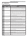
C(F,H,P)X-MODB Rev A Copper-fin II/IIE Boiler, Water Heater and Pool Heater ModBus Communication Instructions Models: 402 - 2072 (Boiler & Water Heater) Models: 502 - 2072 (Pool Heater) WARNING This manual must only be used by a qualified heating installer / service technician. Read all instructions, including this manual, the Installation and Operation Manual, and the Service Manual, before installing. Perform steps in the order given. Failure to comply could result in severe personal injury, death, or substantial property damage. Save this manual for future reference. Contents 1. INTRODUCTION Definitions .................................................................... 2 Minimum System Requirements.................................. 2 2. CONFIGURATION Addressing ................................................................... 3 Timing Specifications ................................................... 4 Parity............................................................................ 4 Data Transmission Mode............................................. 4 ModBus Board Diagnostics ......................................... 4 Internal Faults......................................................... 4 ModBus Function Set ............................................. 5 ModBus Exception Codes ........................................... 6 3. MEMORY MAP Primary Data Tables .................................................... . 7 Copper-fin II/IIE Memory Map ..................................... 7-8 1 Input Registers ....................................................... . 8 Holding Registers ................................................... . 8 Configuration Bits ........................................................ . 8 4. WIRING REQUIREMENTS ModBus Mounting/Wiring Instructions ....................... 9-10 Physical Wiring ...................................................... . 11-13 Typical Boiler System Wiring .................................. 14-15 5. UNIT OPERATION Unit Operation with ModBus Communications...... 16-19 6. TROUBLESHOOTING........................................... 20-21 7. DIAGRAMS Ladder Diagram ..................................................... 22-23 Connection Diagram ................................................24-25 Revision Notes ................................................... Back Cover Introduction The information contained in this manual provides general guidelines for the implementation of ModBus communication with the Lochinvar Copper-fin II/IIE. All ModBus networks are implemented utilizing a master-slave arrangement where all Copper-fins are slaves and the master is a building automation system capable of communicating over a RS-485 serial connection. Definitions Abbreviation or Acronym Meaning ASCII American Standard Code for Information Interchange BAS Building Automation System Baud (Baud Rate) Number of data bits transmitted per second (bps) EMS Energy Management System FDX Full-Duplex HDX Half-Duplex Hex Hexadecimal Number (0 - 9, A - F) I/O Box Input/Output (I/O) LSB Least Significant Byte ModBus® A serial, half-duplex data transmission protocol developed by AEG Modicon MSB Most Significant Byte RS232 A standard for serial, full-duplex (FDX) transmission of data based on the RS232 Standard RS485 A standard for serial transmission of data based on the RS-485 Standard RTU Remote Terminal Unit Minimum System Requirements • BAS system or computer with a serial or USB port with a converter to RS-485. • Copper-fin II/IIE equipped with ModBus communication board. • Shielded twisted pair communication cable. 2 Copper-fin II/IIE Boiler, Water Heater and Pool ModBus Manual 2 Configuration The ModBus communication board is equipped with a set of ten dip switches that are used to set the board configuration (address, baud rate, and parity settings). The first eight are used to set the address of each board. The ninth baud rate. The tenth is parity. Figure 2-1_ModBus Communication Board DIP SWITCHES LED'S Addressing The ModBus addressing space is comprised of 256 different addresses. • 0 is reserved for broadcast messages from the master device • 1 - 247 are free to use for each unique device • 248 - 255 are reserved To set the ModBus address the dip switches can be set in either the 0 position or the 1 position. For switches set to the 1 position their value will be added together to determine the address. Each switch set to the 1 position has the following value: Example: To set the address of the ModBus board to 50, dip switches 2, 5, and 6 have to be set to the 1 position. The address is determined by adding the values of all the dip switches together. Address = Value of Dip switch 1 + Value of Dip switch 2 + Value of Dip switch 3 + Value of Dip switch 4 + Value of Dip switch 5 + Value of Dip switch 6 + Value of Dip switch 7 + Value of Dip switch 8 In this example: Address = 0 + 2 + 0 + 0 + 16 + 32 + 0 + 0 = 50 Dip switch 1 = 1 Dip switch 2 = 2 Dip switch 3 = 4 Dip switch 4 = 8 Dip switch 5 = 16 Dip switch 6 = 32 Dip switch 7 = 64 Dip switch 8 = 128 Any dip switch set to 0 has a value equal to 0. 3 Copper-fin II/IIE Boiler, Water Heater and Pool ModBus Manual 2 Configuration Timing Specifications Data Transmission Mode The baud rate for the ModBus board is selectable with dip switch #9. Many ModBus bus master devices can be configured to transmit data in either ModBus RTU or ModBus ASCII modes. Since RTU messages can be formatted to use fewer data bits and are therefore more efficient, RTU has been chosen to be used with all Lochinvar ModBus communication. Please ensure that the master device is transmitting ModBus RTU. 1 = 19200 bps 0 = 9600 bps Each message is started by at least 3.5 character times of silence. The maximum delay between frames is 1.5 character times. When the system temperature and/or tank temperature is provided by the BAS to the boiler, it is critical that the temperature be updated every few seconds. If the boiler does not receive updated temperatures within a timeout period (installer adjustable), the control will revert to using its own sensor inputs (if sensors are connected). The timeout is programmable by accessing parameter H7 (see the Copper-fin Service Manual for the procedure on how to set parameters). The timeout is adjustable between 1 and 255 seconds. The default timeout is 10 seconds. When the BAS is not providing either of these temperatures, but is still controlling the boiler (such as providing a modulation command), the BAS must refresh these commands at least every 4 minutes. If the commands are not refreshed, the boiler will revert to operating based on its own inputs. Parity Parity is set by the position of Dip switch #10. 0 = No Parity 1 = Even Parity If No Parity is selected there will be two stop bits, otherwise there will be one. 4 ModBus Board Diagnostics The ModBus board is equipped with three LED’s for visual diagnostics: Two yellow LED’s and one green. One yellow LED (D5) is used to indicate reception of data. The other yellow LED (D6) is used to indicate transmission of data. The green LED (D7) is used to show internal faults. Internal Faults: Normal Operation = 1 second bright, 1 second dim Controller Fault = Continuously on No Burner Control Communication = 0.5 seconds on, 1.5 seconds off No ModBus Communication = 1.5 seconds on, 0.5 seconds off ModBus Communication The ModBus communication commands and exception codes that are supported by the ModBus communication board can be found on pages 5 and 6 of this manual. Copper-fin II/IIE Boiler, Water Heater and Pool ModBus Manual 2 Configuration (continued) ModBus Function Set Function Sub Function Dec HEX Description Dec HEX 1 01 Read Coil Status 2 02 Read Input Status 3 03 Read Holding Registers 4 04 Read Input Registers 5 05 Force Single Coil 6 06 Preset Single Register 7 07 Read Exception Status 8 08 0 00 Diagnostic - Return Query Data 1 01 Diagnostic - Restart Communication 2 02 Diagnostic - Return Diagnostic Register 4 04 Diagnostic - Force Listen Mode 10 0A Diagnostic - Clear Counters and Diagnostic Registers 11 0B Diagnostic - Return Bus Message Count 12 0C Diagnostic - Bus Communication Error Count 13 0D Diagnostic - Bus Exception Error Count 14 0E Diagnostic - Return Slave Message Count 15 0F Diagnostic - Return Communication Error Count 16 10 Diagnostic - Return Slave NAK Count 17 11 Diagnostic - Return Slave Busy Count 18 12 Diagnostic - Return Bus Character Overrun Count 20 14 Diagnostic - Clear Overrun Counter and Flag 11 0B Get Communication Event Counter 12 0C Get Communication Event Log 15 0F Write Multiple Coils 16 10 Write Multiple Registers 17 11 Report Slave ID 23 17 Read / Write Multiple Registers 5 Copper-fin II/IIE Boiler, Water Heater and Pool ModBus Manual 2 Configuration ModBus Exception Codes ModBus Exception Codes Code Name Meaning ILLEGAL FUNCTION The function code received in the query is not an allowable action for the server (or slave). This may be because the function code is only applicable to newer devices, and was not implemented in the unit selected. It could also indicate that the server (or slave) is in the wrong state to process a request of this type, for example because it is unconfigured and is being asked to return register values. ILLEGAL DATA ADDRESS The data address received in the query is not an allowable address for the server (or slave). More specifically, the combination of reference number and transfer length is invalid. For a controller with 100 registers, the PDU addresses the first register as 0, and the last one as 99. If a request is submitted with a starting register address of 96 and a quantity of registers of 4, then this request will successfully operate (address-wise at least) on registers 96, 97, 98, 99. If a request is submitted with a starting register address of 96 and a quantity of registers of 5, then this request will fail with Exception Code 0x02 “Illegal Data Address” since it attempts to operate on registers 96, 97, 98, 99 and 100, and there is no register with address 100. 03 ILLEGAL DATA VALUE A value contained in the query data field is not an allowable value for server (or slave). This indicates a fault in the structure of the remainder of a complex request, such as that the implied length is incorrect. It specifically does NOT mean that a data item submitted for storage in a register has a value outside the expectation of the application program, since the ModBus protocol is unaware of the significance of any particular value of any particular register. 04 SLAVE DEVICE FAILURE An unrecoverable error occurred while the server (or slave) was attempting to perform the requested action. 05 ACKNOWLEDGE Specialized use in conjunction with programming commands. The server (or slave) has accepted the request and is processing it, but a long duration of time will be required to do so. This response is returned to prevent a timeout error from occurring in the client (or master). The client (or master) can next issue a Poll Program Complete message to determine if processing is completed. 06 SLAVE DEVICE BUSY Specialized use in conjunction with programming commands. The server (or slave) is engaged in processing a long -- duration program command. The client (or master) should re-transmit the message later when the server (or slave) is free. MEMORY PARITY ERROR Specialized use in conjunction with function codes 20 and 21 and reference type 6, to indicate that the extended file area failed to pass a consistency check. The server (or slave) attempted to read record file, but detected a parity error in the memory. The client (or master) can retry the request, but service may be required on the server (or slave) device. 01 02 08 0A 0B 6 Specialized use in conjunction with gateways, indicates that the gateway was unable to allocate an internal communication path from the input port to the GATEWAY PATH UNAVAILABLE output port for processing as the request. Usually means that the gateway is misconfigured or overloaded. GATEWAY TARGET DEVICE FAILED TO RESPOND Specialized use in conjunction with gateways, indicates that no response was obtained from the target device. Usually means that the device is not present on the network. Copper-fin II/IIE Boiler, Water Heater and Pool ModBus Manual 3 Memory Map Primary Data Tables Table Data Type Read / Write Discrete Inputs Single Bit Read Only Coils Single Bit Read / Write Input Registers 16-Bit Word Read Only Holding Registers 16 Bit Word Read / Write Copper-fin II/IIE Memory Map Address Description 00001 00002 00003 00004 00005 Stage 1 Enable Stage 2 Enable Stage 3 Enable Stage 4 Enable Tank Thermostat 10001 10002 10003 10004 10005 10008 10009 10010 10011 10012 10013 10023 10024 10033 10034 10035 10036 10037 10038 10039 High Limits Flow Switch Gas Pressure Switch Louver Proving Switch Air Pressure Switch Flame 1 Stage 1 On Tank Thermostat Stage 2 On Stage 3 On Stage 4 On Flame 2 Enable 2 Runtime Contacts Alarm Contacts HTR Pump DHW Pump Louver Relay Gas Valve 1 System Pump Default Unit Coils 0 1=ON / 0=OFF 0 1=ON / 0=OFF 0 1=ON / 0=OFF 0 1=ON / 0=OFF 0 1=ON / 0=OFF Discrete Inputs 0 1=ON / 0=OFF 0 1=ON / 0=OFF 0 1=ON / 0=OFF 0 1=ON / 0=OFF 0 1=ON / 0=OFF 0 1=ON / 0=OFF 0 1=ON / 0=OFF 0 1=ON / 0=OFF 0 1=ON / 0=OFF 0 1=ON / 0=OFF 0 1=ON / 0=OFF 0 1=ON / 0=OFF 0 1=ON / 0=OFF 0 1=ON / 0=OFF 0 1=ON / 0=OFF 0 1=ON / 0=OFF 0 1=ON / 0=OFF 0 1=ON / 0=OFF 0 1=ON / 0=OFF 0 1=ON / 0=OFF Min. Max. Resolution Calculation Factor 0 0 0 0 0 1 1 1 1 1 1 1 1 1 1 1 1 1 1 1 0 0 0 0 0 0 0 0 0 0 0 0 0 0 0 0 0 0 0 0 1 1 1 1 1 1 1 1 1 1 1 1 1 1 1 1 1 1 1 1 1 1 1 1 1 1 1 1 1 1 1 1 1 1 1 1 1 1 1 1 1 1 1 1 1 1 1 1 1 1 1 1 1 1 1 1 1 1 1 1 7 Copper-fin II/IIE Boiler, Water Heater and Pool ModBus Manual 3 Memory Map Copper-fin II/IIE Memory Map Address 10046 10047 10048 30001 30002 30003 30004 30005 30006 30007 30008 30009 30010 30011 30012 30014 30015 30016 40001 40002 40003 40004 40005 40006 40007 40008 Description Default Gas Valve 2 Gas Valve 3 Gas Valve 4 Unit Min. 0 1=ON / 0=OFF 0 0 1=ON / 0=OFF 0 0 1=ON / 0=OFF 0 Input Registers Discrete Inputs 1 - 16 0 N/A 0 Discrete Inputs 17 - 32 0 N/A 0 Discrete Inputs 33 - 48 0 N/A 0 System / Cascade Set point 0 °C 0 System Pump Speed 0 % 0 Cascade Total Power 0 % 100 Cascade Current Power 0 % 0 Outlet Set point 0 °C 0 Outlet Temperature 0 °C 0 Inlet Temperature 0 °C -20 Pool Temperature 0 °C -20 Firing Rate 0 % 0 Status Code 0 N/A 0 Blocking Code 0 N/A 0 Lockout Code 0 N/A 0 Holding Registers Configuration 0 N/A 0 Coils 0 N/A 0 0 - 10V Inp. / Rate Cmd / Setp. Cmd 0 % 0 Pool Set point 0 °C 0 Tank Temperature 0 °C -20 Outdoor Temperature 0 °C -40 System Supply Temperature 0 °C -20 System Return Temperature 0 °C -20 1 1 1 1 1 1 Calculation Factor 1 1 1 65535 65535 65535 130 100 800 800 130 130 130 130 100 65535 65535 65535 1 1 1 0,5 1 1 1 0,5 0,1 0,1 0,1 1 1 1 1 1 1 1 0,5 1 1 1 0,5 0,1 0,1 0,1 1 1 1 1 65535 65535 100 87,5 130 60 130 130 1 1 1 0,5 0,1 0,1 0,1 0,1 1 1 1 0,5 0,1 0,1 0,1 0,1 Max. Resolution Configuration Bits Address 40001 contains configuration bits sent from the BAS to the boiler. These bits tell the boiler to use its own internal inputs, or inputs from the BAS. When a bit is set to 1, the boiler will ignore the corresponding value contained internally, and expect the BAS to write that value into the Holding Registers. The configuration bits are as follows: Bit 0 (LSB): Boiler Enable Bit 1: Tank Thermostat Bit 2: Rate Command / 10 - 10V Input / Set point Command Bit 3: Tank Set point 8 Bit 4: System Supply Temperature Bit 5: Outdoor Temperature Bit 6: Tank Temperature Bit 7: System Return Temperature Bit 8 - 15: Not Used (Default = 0) Copper-fin II/IIE Boiler, Water Heater and Pool ModBus Manual 4 Wiring Requirements ModBus Mounting/Wiring Instructions 1. Turn OFF power at the source. 2. Remove the left and right access panels to access the inside of the unit. 3. Mount the ModBus board as shown in FIG. 4-1. - Set dip switch settings (reference Section 2 Configuration) and make the necessary ground connections. 4 Locate the control panel (see FIG. 4-2 on page 10). Locate the bushing on the right-hand side of the control panel (FIG. 4-2). 5. Route the ModBus harness (WRE20129) A1, A2, A3, and A4 housing through the bushing on the right-hand side of the control panel. 6. Locate and disconnect the controller transformer from the line voltage harness (FIG. 4-2). 7. Plug ModBus harness A1 into the line voltage harness connection (FIG. 4-2). 8. Plug ModBus harness A1 into the line voltage harness connection (FIG. 4-2). 9. Locate the digital harness connector (FIG. 4-2). Plug ModBus harness A3 into the digital harness connector. Figure 4-1_Mounting the ModBus Control Board INSTALLATION: LOCATE MODBUS BRACKET ON DV PANEL AND SECURE WITH SELF DRILLING SCREWS. ADD ALUMINUM SPACERS TO BRACKET STUDS. ADD MODBUS CONTROL BOARD (MTR01) AND SECURE WITH MOUNTING NUTS. ADD MODBUS COVER AND SECURE WITH SHEET METAL SCREWS. REPLACEMENT: REMOVE SHEET METAL SCREWS AND MODBUS COVER. REMOVE MOUNTING NUTS AND MODBUS CONTROL BOARD (MTR01). REPLACE BOARD AND SECURE WITH MOUNTING NUTS. ADD MODBUS COVER AND SECURE WITH SHEET METAL SCREWS. 10. Route WRE20129 along the front edge of the unit. Note: Take care not to run the wiring over any sharp edges. 11. Locate the ModBus cover. Run ModBus power A5 through the top bushing of the ModBus cover. 12. Run ModBus harness A6 and A7 through the lower bushing of the ModBus cover. 13. Wire the ModBus as follows (FIG. 4-2): • Connect A5 to ModBus board X1 • Connect A6 to ModBus board X4 • Connect A7 to ModBus board X6 14. If it is desired to ground the communication cable shield at the heater, install a jumper wire between pins 1 and 3 of X5. 15. Replace the ModBus cover. Secure the cover using the two (2) screws provided with the ModBus. 16. Test the unit before replacing the access panels. 17. Replace the left and right access panels and turn ON power at the source. Resume operation. 9 Copper-fin II/IIE Boiler, Water Heater and Pool ModBus Manual Wiring Requirements 4 Figure 4-2_Schematic / Wire Connections LINE VOLTAGE HARNESS 23 22 A SHIELD SENSOR TANK DIGITAL HARNESS 24 28 27 - RATE OUT - BMS IN + 0-10V SHIELD B 29 + 0-10V A SHIELD 30 33 SHIELD B 32 31 26 25 CN2 34 35 CONNECTION BOARD CN6 CN1 A3 A4 A1 CONTROL PANEL CONNECTION BOARD A2 BUSHING CONTROLLER TRANSFORMER MODBUS HARNESS WRE20129 RECOMMENDED HARNESS ROUTING A5 A6 A7 WRE20129 MODBUS BOARD MODBUS BOARD 10 CASCADE MODBUS Copper-fin II/IIE Boiler, Water Heater and Pool ModBus Manual 4 Wiring Requirements (continued) Note that when the System Supply Temperature and/or the Tank Temperature are provided by the BAS, they need to be refreshed every few seconds. This is required in order to prevent unwanted fluctuations in these temperatures. If these values are not provided every few seconds (timeout is programmable), the boiler will revert to its own internal control. If neither of these temperatures is provided by the BAS, but any of the other control signals are being provided, the BAS will still need to refresh these inputs at least every 4 minutes. Physical Wiring RS-485 Communication Bus • Maximum Length = 4000 feet • Cable Specification = 24 AWG / A,B (twisted pair) and GND Shielded, with characteristic Impedance = 120 ohm • Maximum Load = 32 units (32 nodes) NOTE: Cable must be terminated with 120 ohm impedance matching resistor on each end. EXTERNAL SEQUENCER/ BUILDING AUTOMATIC CONTROL TANK 23 SENSOR 24 SHIELD B 25 A A 26 B 27 SHIELD 28 + 0-10V 29 - BMS IN 30 + 0-10V 31 - RATE OUT 32 SHIELD 33 A 34 B 35 SHIELD A B OPTIONAL MODBUS OPTIONAL MODBUS SHIELD A B MODBUS FROM PREVIOUS HEATER TO NEXT HEATER (if used) 22 CASCADE Figure 4-3_Terminal Strip Connections CN2 TO NEXT BOILER SHIELD A B 11 Copper-fin II/IIE Boiler, Water Heater and Pool ModBus Manual 4 Wiring Requirements Figure 4-4_Control Inputs OUTDOOR SENSOR (OPTIONAL) SYSTEM SUPPLY/ ENABLE SENSOR (OPTIONAL) SYSTEM RETURN/ POOL SENSOR (OPTIONAL ON BOILER) (STD ON POOL HEATER) LOW VOLTAGE CONNECTION BOARD SYSTEM PUMP SPEED (OPTIONAL) SENSOR CONNECTION BOARD (BOILER AND POOL HEATER ONLY) CASCADE DHW THERMOSTAT (OPTIONAL) ROOM THERMOSTAT/ ZONE CONTROL (OPTIONAL) SEQUENCER BUILDING MANAGEMENT SYSTEM (FIELD PROVIDED) LOUVER PROVING SWITCH (FIELD PROVIDED) TANK SENSOR (OPTIONAL) MODBUS SMART SYSTEM CONTROL BOARD MODBUS BOARD (OPTIONAL) INLET TEMPERATURE SENSOR OUTLET TEMPERATURE/ LIMIT SENSOR LOW WATER CUTOFF (OPTIONAL) GAS PRESSURE SWITCH (OPTIONAL) MANUAL RESET HIGH LIMIT (OPTIONAL) AIR PRESSURE SWITCH FLOW SWITCH DISPLAY PANEL PC INTERFACE (OPTIONAL) PC INTERFACE 12 Copper-fin II/IIE Boiler, Water Heater and Pool ModBus Manual 4 Wiring Requirements (continued) Figure 4-5_Control Outputs MODBUS BOARD (OPTIONAL) MODBUS LOW VOLTAGE CONNECTION BOARD 0-10V RATE CASCADE THREE WAY VALVE (OPTIONAL ON BOILER) (STD ON POOL HEATER) LOUVER RELAY BUILDING MANAGEMENT SYSTEM RUN TIME CONTACTS ALARM CONTACTS SMART SYSTEM CONTROL BOARD ALARM (OPTIONAL) HEATER PUMP (BOILER ONLY) PC INTERFACE SYSTEM PUMP RELAY DHW PUMP RELAY (BOILER) DHW PUMP (WATER HEATER) HOT SURFACE IGNITER BLOWER GAS VALVES DISPLAY PANEL PC INTERFACE (OPTIONAL) INDICATES CONNECTIONS MADE TO THE LINE VOLTAGE TERMINAL STRIP LOCATED IN THE CONTROL PANEL AREA 13 Copper-fin II/IIE Boiler, Water Heater and Pool ModBus Manual 4 Wiring Requirements Figure 4-6_Control Location CONTROL PANEL MODBUS COMMUNICATION BOARD (MTR01) CONTROL PANEL CONNECTION BOARD CONNECTION BOARD Models 402 - 752 Models 992 - 2072 Typical Boiler System Wiring Physical Configuration: Cascade without Individual Monitoring ModBus RS485 Port on Gateway or Building System ModBus RS485 Communication Bus Cascade Daisy Chain Connection 14 MODBUS COMMUNICATION BOARD (MTR01) Copper-fin II/IIE Boiler, Water Heater and Pool ModBus Manual 4 Wiring Requirements (continued) Physical Configuration: Cascade with individual Monitoring ModBus RS485 Port on Gateway or Building System ModBus RS485 Communication Bus Cascade Daisy Chain Connection Physical Configuration: Direct Control ModBus RS485 Port on Gateway or Building System ModBus RS485 Communication Bus 15 Copper-fin II/IIE Boiler, Water Heater and Pool ModBus Manual 5 Unit Operation Unit Operation with ModBus Communications A Building Automation System (BAS) can monitor the Copper-fin II/IIE without the need to change the default configuration of the SMART SYSTEM control. When the BAS is to provide commands or values to the control, parameter H6 ModBus must be set to Active (reference the Copper-fin II/IIE Service Manual for the procedure on how to set parameters). The SMART SYSTEM control is equipped with two (2) ModBus communication timers. The first is used whenever the control receives the system temperature and/or the tank temperature through ModBus. These values need to be updated on a regular basis to prevent unwanted temperature variations. This timer is programmable from 1 to 255 seconds. It is Lochinvar’s recommendation that this timer be set as short as possible. This timeout can be adjusted by accessing parameter H7 ModBus Time. The timer is reset with the ModBus Time setting every time the temperatures are updated. The second timer is used for all other commands and values provided through ModBus. It has a fixed timeout of four (4) minutes. If either of these timers expire before the next update, the SMART SYSTEM control will revert to using its local inputs. When a BAS is to control a Copper-fin II/IIE, the installer must configure the SMART SYSTEM control to receive commands and data through ModBus. There are several different control methods available, as described in this section. These methods are determined by the settings in four (4) different parameters. Control Mode 1 In this configuration the heater is enabled and disabled through ModBus. The heater uses its own local set points. All sensors and limiting devices should be connected directly to the terminal strip(s) inside the Copper-fin II/IIE control compartment. The Enable 1 and/or Tank Thermostat signals will be sent to the heater through ModBus. Holding Registers Definition Bit Value (HEX) Action 40001 Configuration 00 01 00 02 00 03 Read Enable 1 status Read Tank Thermostat status Read Enable 1 and Tank Thermostat status 40002 Coils 00 01 00 02 00 03 Enable 1 only active Tank Thermostat only active Enable 1 and Tank Thermostat active NOTE: To ensure proper operation, re-send the configuration bits to holding register 40001 prior to issuing commands. Control Mode 2 In this configuration, each stage is enabled directly (boiler only). Control Mode 2 - Setup (Configuration Parameters) To control each stage separately, access parameters H5 Sequencer, and set it to Active (reference the Copper-fin II/IIE Service Manual for the procedure on how to set the parameters). Control Mode 2 - Setup (Command Parameters) The holding register will need to be set as follows: Holding Registers Definition Bit Value (HEX) Action 40001 Configuration 01 01 03 01 07 01 Read Enable 1 and 2 (2-stage heaters) Read Enable 1, 2, and 3 (3-stage heaters) Read Enable 1, 2, 3, and 4 (4-stage heaters) Coils 00 01 00 03 00 07 00 0F Enable Stage 1 Enable Stages 1 and 2 Enable Stages 1, 2, and 3 Enable Stages 1, 2, 3, and 4 40002 NOTE: To ensure proper operation, re-send the configuration bits to holding register 40001 prior to issuing commands. 16 Copper-fin II/IIE Boiler, Water Heater and Pool ModBus Manual 5 Unit Operation (continued) Control Mode 3 In this configuration, the heater receives its enable signal and a rate command through ModBus. All sensors and limiting devices should be connected directly to the terminal strip(s) inside the Copper-fin II/IIE control compartment. Control Mode 3 - Setup (Configuration Parameters) To send a rate signal to the SMART SYSTEM control, access parameter H3 BMS input and set it to Active (reference the Copperfin II/IIE Service Manual for the procedure on how to set parameters). Control Mode 3 - Setup (Command Parameters) The holding register will need to be set as follows: Holding Registers Definition Bit Value (HEX) Action 40001 Configuration 00 05 Read Enable 1 and 0-10V input 40002 Coils 00 01 Enable 1 Active 40003 0-10V Input 00 ## Sets % rate NOTE: To ensure proper operation, re-send the configuration bits to holding register 40001 prior to issuing commands. See the Rate and Temperature Conversions Section on page 19 for instructions on how to send the % rate. Control Mode 4 In this configuration, the heater receives its enable signal and set points through ModBus. All sensors and limiting devices should be connected directly to the terminal strip(s) inside the Copper-fin II/IIE control compartment. Control Mode 4 - Setup (Configuration Parameters) To send a Space Heating set point to the SMART SYSTEM control, access parameter H3 BMS input and set it to Active. Also, access parameter J1 BMS Type and set it to Set point (reference the Copper-fin II/IIE Service Manual for the procedure on how to set parameters). The space heating set point will be derived from the 0-10V input value, based on the BMS settings in the control. Reference the Copper-fin II/IIE Service Manual for details of these parameters. Control Mode 4 - Setup (Command Parameters) The holding register will need to be set as follows: Holding Registers Definition Bit Value (HEX) Action 40001 Configuration 00 05 00 08 00 09 00 0D Read Enable 1 and 0-10V input Read Tank/Pool Set point Read Enable 1 and Pool Set point Read Enable 1, 0-10V input, and Tank Set point 40002 Coils 00 01 Enable 1 active 40003 0-10V Input 00 ## Sets space heating set point 40004 Tank/Pool Set point 00 ## Sets Tank or Pool set point NOTE: To ensure proper operation re-send the configuration bits to holding register 40001 prior to issuing commands. See the Rate and Temperature Conversions Section on page 19 for instructions on how to send the Tank/Pool set point. 17 Copper-fin II/IIE Boiler, Water Heater and Pool ModBus Manual 5 Unit Operation Control Mode 5 In this configuration, the heater receives its enable and its rate or set point using the 0-10V input through ModBus. All sensors and limiting devices should be connected directly to the terminal strip(s) inside the Copper-fin II/IIE control compartment. Control Mode 5 - Setup (Configuration Parameters) To use the 0-10V input as an enable, access parameter H2 Enable input in the SMART SYSTEM control, and set this parameter to Inactive. Also, access parameter H3 BMS input and set it to Active. If you wish to control the set point, access parameter J1 BMS Type and set it to Set point. The enable function and the space heating set point will be derived from the 0-10V input value, based on the BMS settings in the control. Reference the Copper-fin II/IIE Service Manual for the details of these parameters. Control Mode 5 - Setup (Command Parameters) The holding register will need to be set as follows: Holding Registers Definition Bit Value (HEX) Action 40001 Configuration 00 04 Read 0-10V input 40003 0-10V Input 00 ## Sets space heating rate or set point NOTE: To ensure proper operation, re-send the configuration bits to holding register 40001 prior to issuing commands. See the Rate and Temperature Conversions Section on page 19 for instructions on how to send the rate. Hot Water Generation Hot water generation can be accomplished with one of two methods when a Copper-fin II/IIE is connected to a BAS system, DHW with direct control, and DHW with remote control. DHW with direct control: This is the typical installation with a hot water generator in close proximity to the boiler with the tank thermostat, or tank temperature sensor, wired to the terminal strip of the unit. DHW with remote control: This installation may or may not have the hot water generator in close proximity to the boiler. Its sensors and thermostat values are only available through the ModBus communication bus. To ensure that the Copper-fin II/IIE can properly respond to a call for hot water generation the following holding registers must be set in addition to other commands: Holding Registers Definition Bit Value (HEX) Action 40001 Configuration 00 4A Set Configuration to read 40002, 4 & 5 40002 Coils 00 08 Enables Tank Tstat (00 00 disables unit) 40004 Tank Set point 0# ## Sets Set point 40005 Tank Temperature 0# ## Passes tank temp from remote sensor NOTE: To ensure proper operation re-send the configuration bits to holding register 40001 prior to issuing commands. For proper hexadecimal conversion of rate percentage, please refer to the Rate and Temperature Conversion section on page 19 of this manual. 18 Copper-fin II/IIE Boiler, Water Heater and Pool ModBus Manual 5 Unit Operation (continued) Cascade In order to operate the Copper-fin II/IIE in Cascade with ModBus communications, configure the leader boiler per the demand configurations in this manual. Connect the remaining boilers in the cascade through the normal cascade communications wiring. Cascade control can then be accomplished automatically through the leader boiler. Please note that with ModBus communication connected to only the leader boiler, total Cascade information can be seen through the communications link. If you wish to see all the individual temperatures of each unit in the Cascade, each unit will have to have a ModBus communication board. However, each unit can be monitored without the need to control each one individually. Monitoring Only Any Copper-fin II/IIE can be equipped with the ModBus communication board and then be set up to operate with its own internal controls. If necessary, ModBus can be configured as a monitoring device by selecting demand configurations 1 - 3, and polling the ModBus board for the read only variables. Rate and Temperature Conversions: Rate When issuing a rate command the rate can be communicated as percent modulation or a desired set point, depending on the setting of the BMS Type in the BMS Setup Menu. The proper data format for the modulation percentage is the direct conversion to hexadecimal. This conversion can be accomplished through online number based converters or some scientific calculators. For Example: Rate % HEX 0 20 45 60 80 95 100 00 14 2D 3C 50 5F 64 To send a desired set point, the hexadecimal value must be determined through linear interpolation of programmable parameters on the BMS Setup Menu: - BMS temperature set-point at low analog input - BMS temperature set-point at high analog input These variables set the temperature values corresponding to the minimum and maximum voltage settings of the 0-10 volt signal. The defaults are as follows: PARAMETER DEFAULT VALUES DEFAULT Deg C Deg F Voltages BMS temperature set point at low analog input 21 69.8 2 BMS temperature set point at high analog input 82 179.6 10 For Example: Send a set point of 110°F. The formula to use for the interpolation is: Rate Command = (Desired Set point – BMS Temp at Low Analog Input) (High Voltage-Low Voltage) + Low Voltage (BMS Temp at High Analog Input – BMS Temp at Low Analog Input) From the default values: Desired Set point = 110 BMS Temp at Low Analog Input =68 BMS Temp at High Analog=158 High Voltage =10 Low Voltage = 2 [(110-69.8)(10-2)/(179.6-69.8)] + 2 = 4.92 Volts (4.92/10) x 100 = 49.2 49 = 31 Hexadecimal A value of [00][31] in hexadecimal would be written to Holding register 40003 to issue a command for a 110°F set point. Temperature The Copper-fin II/IIE passes temperature data in degrees Celsius. Also, to accommodate decimal places the decimal value must be divided by 10. Here are the conversions to and from Celsius: Tc = (5/9) * (Tf-32) Tf = (9/5) * Tc+32 Example: Outdoor temperature from remote sensor on BAS System = 80°F 80°F = 26.7°C Data that needs to be transmitted is 26.7 * 10 = 267 Decimal Binary HEX 267 100001011 10B Outlet temperature from unit sensor = 155°F 155°F = 68.3°C Data transmitted from unit in HEX = 2AB = 683 683 ÷ 10 = 68.3 (°C) Decimal Binary HEX 683 1010101011 2AB 19 Copper-fin II/IIE Boiler, Water Heater and Pool ModBus Manual 6 Troubleshooting Should you encounter problems communicating over ModBus, the following items should be checked in this order: 1. 2. 3. 4. Physical Layer Communications Configuration and Port Settings ModBus Error Codes Unit Status / Blocking / Lockout Codes Physical Layer 1. 2. 3. 4. 5. 6. Check that all components have power (Boiler, Gateway, BAS Master) Check all wire lengths. Are any drops too long? Check proper shield grounding Check A, B terminal connections Check for Terminating Resistors (120 ohms) Check for broken wires Communications 1. 2. 3. 4. 5. Check Dip Switch Configuration of MTR-01 Board Check Baud Rate (9600, 19200) Check Parity Check Slave ID Check Port Setting on Master, Gateway, and Computers ModBus Error Codes 1. 2. 3. 4. 5. 6. Check ModBus communication for error codes (see page 6 for ModBus Exception Codes) Check ModBus PDU Check Slave ID Check ModBus Command Check Configuration bits for Holding Register 40001 Check Commands and data for Holding Registers 40002 - 40007 Unit Status Codes See Codes in this section Boiler Status The Copper-fin II/IIE displays a boiler state code on the Building Screen to help aid in troubleshooting. The boiler state indicates what the boiler is actually doing. This state should be compared to the command issued and what is expected. If the boiler state does not agree with the command issued, check communication and configuration. 20 Status Codes (Input Registers 30014 and 30023) 2 = Heat Demand blocked due to high absolute outlet temperature 3 = Heat Demand blocked due to high absolute flue temperature 4 = Heat Demand blocked due to high absolute Delta T (Outlet - Inlet) 8 = Heat Demand blocked due to Low 24 VAC 9 = Outdoor shutdown 10 = Block due to switch OFF boiler (ON/OFF of Display) 12 = Block due to no correct communication Cascade 16 = Service function 19 = DHW function Storage Tank 21 = SH function Heat demand from Room Thermostat 22 = SH function Heat demand from Boiler Management System 23 = SH function Heat demand from Cascade 30 = Heat demand activated by Freeze Protection 32 = DHW Pump Delay 33 = SH Pump Delay 34 = No heat function (after pump delay) 40 = Lockout 32764 = Busy with updating status 32765 = DHW blocked due to no present tank sensor 32766 = Burner control(s) manually shut down 32767 = Code not present Blocking Codes (Input Registers 30015 and 30024) 0= 1= 2= 3= 4= 5= No blocking _> is divided into sub blockings SH blocking Blocking Due to Low 24 VAC Supply Blocking due to General block Blocking MRHL is open Blocking due to Switched OFF boiler (Display ENTER switch) 6 = Blocking due to wrong communication of Cascade 7 = Blocking due to High Delta 8 = Blocking due to High Flue Temperature 9 = Blocking due to High Outlet Temperature 10 = Service blocking 12 = DHW blocking high outlet temperature (DHW configured as storage tank) 13 = Blocking anti-cycling time 14 = Storage Tank demand Blocked due to Fan problems 15 = No system sensor connected and leader control present 16 = Limit fan speed due to high outlet temperature 17 = Fan min decreased due to low flame current 18 = Limit max fan speed due to high Delta T 19 = Limit max fan speed due to high flue temp 32767 = Code not present Copper-fin II/IIE Boiler, Water Heater and Pool ModBus Manual 6 Troubleshooting (continued) Lockout Codes (Input Registers 30016 and 30025) 1. Turn OFF the main electrical power to the appliance. 161 = 2. Turn OFF the main manual gas shutoff to the appliance. 3. Unplug the three (3) wire harnesses on the MTR01 control board (see FIG. 6-1). 4. Unscrew the four (4) mounting nuts on the MTR01 control board and set aside. Remove the MTR01 control board (see FIG. 6-2). 5. Replace / install the new MTR01 control board. 6. Replace the four (4) mounting nuts removed in Step 4. 7. Reconnect all three (3) wire harnesses unplugged in Step 3. 8. Turn on the main electrical power and the main manual gas shutoff to the appliance. 9. Configure the MTR01 control board and unit controls per this manual and resume operation. EEPROM code Parameters not Re-Programmed by Lochinvar 164 = EEPROM code No Reset Allowed (> 15 minutes) 166 = EEPROM code Auto Reset High Limit 167 = EEPROM code Blocked Drain 168 = EEPROM code Louver Proving 169 = EEPROM code Gas Pressure Sw 170 = EEPROM code Flow Switch 177 = Sensor 3 short (Flue Sensor) 178 = Sensor 3 open (Flue Sensor) 179 = Sensor 2 short (Inlet Sensor) 180 = Sensor 2 open (Inlet Sensor) 192 = Sensor 1 short (Outlet Sensor) 193 = Sensor 1 open (Outlet Sensor) 204 = CRC EEPROM failed 205 = EEPROM programmed (display shows “PP”) 206 = EEPROM error in programming 207 = Write error EEPROM 229 = EEPROM code Watch Dog 230 = EEPROM code fan low (should be high) 231 = EEPROM code fan high (should be low) 232 = EEPROM code no flame when running 233 = EEPROM code no flame after ignition 234 = EEPROM code simultaneous output APS and Fan 235 = EEPROM code APS active not Closed 236 = EEPROM code APS active not Open 237 = EEPROM code flame out of sequence 239 = EEPROM code when gas valve relay test fails 240 = EEPROM code MRHL 32767 = Code not present Figure 6-2_Control Panel w/MTR01 Control Board INSTALLATION: LOCATE MODBUS BRACKET ON DV PANEL AND SECURE WITH SELF DRILLING SCREWS. ADD ALUMINUM SPACERS TO BRACKET STUDS. ADD MODBUS CONTROL BOARD (MTR01) AND SECURE WITH MOUNTING NUTS. ADD MODBUS COVER AND SECURE WITH SHEET METAL SCREWS. REPLACEMENT: REMOVE SHEET METAL SCREWS AND MODBUS COVER. REMOVE MOUNTING NUTS AND MODBUS CONTROL BOARD (MTR01). REPLACE BOARD AND SECURE WITH MOUNTING NUTS. ADD MODBUS COVER AND SECURE WITH SHEET METAL SCREWS. Installation / Replacement Procedure Figure 6-1_MTR01 Control Board UNPLUG THREE (3) WIRE HARNESSES 21 L 22 5A F6 5A F5 X2-1 X2-2 CIRCUIT BREAKER X12-5 X12-6 STAGE 3 GAS VALVE STAGE 4 GAS VALVE X12-2 X12-3 X6-4 X12-1 X10-6 X10-3 STAGE 2 GAS VALVE CHASSIS 120 VAC LOW VOLTAGE BOX DEPICTS OPTIONAL ITEMS X10-5 X1-3 X1-2 X1-12 X1-3 UNIT PUMP RELAY INTERGRATED CONTROL BOARD X10-1 X10⁻² STAGE 1 GAS VALVE TRANSFORMER TRANSFORMER DHW PUMP RELAY (BOILER) G X12-4 X10⁻⁴ WHERE POSSIBLE, SWITCHES ARE SHOWN WITHOUT UTILITIES (GAS, WATER OR ELECTRICITY) CONNECTED TO THE UNIT. AS SUCH, ACTUAL SWITCH STATES MAY VARY FROM THOSE SHOWN ON DIAGRAMS DEPENDING UPON WHETHER UTILITIES ARE CONNECTED OR A FAULT CONDITION IS PRESENT. SEE WIRING DIAGRAM FOR ADDITIONAL NOTES. MANUAL RESET HIGH LIMIT X1-10 STAGE 3 HSI X1-7 STAGE 1 HSI X1-4 UNIT PUMP RELAY HI/LO SPEED RELAY BLOWER RELAY N BLOWER SYSTEM / TERMINAL TERMINAL RECIRC STRIP STRIP PUMP RELAY LOW SPEED HIGH SPEED MODBUS INTERFACE BOARD CIRCUIT BREAKER OR FUSE X1-1 X1-2 F4 X1-1 X2-4 3.15A 5A X1-8 F2 INTERGRATED CONTROL BOARD HI/LO SPEED RELAY HI/LO SPEED RELAY N 7 X1 -6 ON/OFF SWITCH BLOWER RELAY TERMINAL STRIP Copper-fin II/IIE Boiler, Water Heater and Pool ModBus Manual Diagrams Figure 7-1 Ladder Diagram LOW WATER CUTOFF X6-7 X6-11 X6-14 CN5-10 CN5-12 CN5-4 STAGE 4 TANK TSTAT B COMPUTER DISPLAY BOARD X8-16 X8-6 X8-17 X8-7 CN6-7 CN6-3 X7-4 X7-8 CN6-10 CN6-5 X8-5 X8-15 CN6-9 CONNECTION BOARD 2 CN1-7 + SYSTEM PUMP CN1-8 SPEED INPUT - CASCADE A 0-10V + RATE OUTPUT - 0-10V + BMS INPUT - CN6-4 X6-15 CN5-3 STAGE 3 LOUVER PROVING X6-6 CN5-9 X13-1 CN5-8 X6-2 X6-16 STAGE 2 CN5-7 CN5-1 X6-1 X6-5 X6-12 X6-3 STAGE 1 / ENABLE CLOSE OPEN PROBE TEST (( ( (( 24V COM 24V 3 WAY VALVE CONNECTION BOARD 1 HIGH GAS PRESS SWITCH BLOCKED FLUE RESET J2 -2 J3-3 FLOW SWITCH X11 X4 CN5-11 10K X8-20 X8-10 X8-18 X8-12 X8-1 X8-8 X4-2 X4-1 X4-3 CN1 -1 MODBUS INTERFACE BOARD X6-2 X6-1 X6-3 CN1-2 CN1-3 CN1-1 CN6-8 CASCADE SHIELD TANK SENSOR S4 CONNECTION BOARD 1 CN6 -1 2ND OUTLET SENSOR S9 OUTLET SENSOR S1 X8-2 SYSTEM / POOL RETURN SENSOR S7 INLET SENSOR S2 CN6-6 CN1-6 CN1-5 SYSTEM / POOL SUPPLY SENSOR S6 20K 2ND POOL SUPPLY SENSOR S8 OUTDOOR SENSOR S5 CONNECTION BOARD 2 RUNTIME CONTACTS LOUVER RELAY X8-3 X8-13 X8-14 POOL X8-19 X8-11 BOILER CN1-2 CN4-6 X3-2 X6-10 CN4-5 X3-1 X6-13 ALARM 2 1 B A MODBUS RTU SHIELD CN5-5 ALARM CONTACTS CONNECTION BOARD 1 CONNECTION BOARD 1 SILENCE CN4-4 X3-4 ALARM RELAY CN4-1 X3-3 Diagrams CN5-6 LOW GAS PRESS J2 -1 J2-3 J3-4 J3-2 7 AIR PRESSURE J3-5 J3-6 Copper-fin II/IIE Boiler, Water Heater and Pool ModBus Manual (continued) Figure 7-1 Ladder Diagram cont’d LBL20083 REV B 23 Copper-fin II/IIE Boiler, Water Heater and Pool ModBus Manual 7 Diagrams Figure 7-2 Connection Diagram FIELD WIRING + ALARM 1 + CONTACTS 2 3 + RUNTIME TO MONITORING DEVICE + CONTACTS 4 + OPEN 3-WAY 5 + OPEN 24V CLOSE CLOSE CN4 VALVE 6 + COM COMMON 7 + S1 STAGE #1 8 S1 9 + + S2 CONNECT STAGE #2 10 S2 TO 11 + TERMINAL 12 + S3 STAGE #3 #19 S3 13 + (LOUVER 14 + S4 STAGE #4 RELAY) + S4 15 COM FIELD CN5 16 + LOUVER PROVING PROVE + SWITCHSUPPLIED 17 + LOUVER RELAY LINE WIRING R 18 M + COIL 19 + NEU TANK 20 AQUASTAT + AQUASTAT 21 CN3 + TANK TANK SENSOR 22 + SENSOR 23 24 + SHIELD CN6 + A UNITS 25 B 26 + SHIELD + 27 FROM 0-10V DC IN 28 + +0-10V BMS + -BMS IN COMMON 29 0-10V DC OUT TO 30 + +0-10V + -RATE OUT COMMON BMS 31 CN1 32 + SHIELD MOD + A BUS 33 + B 34 BMS SHIELD 35 + CN2 POOL OUT SAFETY OUTDOOR BK DOOR 10K 1 + SENSOR SUPPLY AIR G + 10K 20K 2 + SYS SUPPLY R 3 10K/20K W 10K SENSOR 10K + 10K 4 + SYS RETURN POOL/BOILER 10K 5 CN1 + SENSOR10K FROM 6 0-10V DC IN + 0-10V SYS PUMP 7 + - PUMP IN COMMON OUTPUT 8 CN2 OPT. ALARM HARNESS TO MONITORING DEVICE PR 1 3-WAY VALVE BL 2 Y LOUVERS STAGING BR R/O 3 T/W 4 Y 5 BL 6 3 5 P DIGITAL HARNESS 6 P 7 BR/W 8 R 9 R/BK 10 R/W G 12 GY 10 BK/W 8 BK 6 P 4 BR/W 2 F2 7 GY F4 3 W X1 1 PR 11 GY 12 W/BK CONTR F5 Y CASCADE 1 BR/W 3 BL 4 PR 5 6 R/W 7 BR BK 8 Y/G 9 BL/BK GY/W 2 GY/W 1 10 O/R P X2 F6 Y 3 2 Y 4 R 1 MODBUS MODULE CONNECTIONS POO L SUP SENSO R MODBUS 1 LOW VOLT HARNES 4 PR 1 5 2 T BK 4 PR 3 PR 2 P 1 P X3 6 W/R X10 7 R/BK X12 8 BK/R X9 BOILER/POOL HEATER SAFETY OUTLET SENSOR INLET SENSOR 10K/20K G 4 W 3 10K 2 1 W/BK 2 BK R W 1 4 Y 3 Y DISPLAY BR BR 24V COM G MAIN POWER HARNESS OPT. MODBUS HARNESS SYSTEM PUMP RELAY COIL R 120V W P Y 2 BL 3 3 2 Y BL CKT. BREAKER G BR BR BR BR BK G BR/ W BK W 120V/60Hz NEUTRAL SUPPLY LINE 24 60VA PR 1HP UNIT MAX PUMP GROUND 1 BK 3 W BK 1 G 2 3 W S3/S4 Y S1/S2 24V W CONTROLLER XFMR 120V IND-DHW PUMP RELAY COIL R 120V Y 24V GROUND BK CHASSIS GROUND W ON/OFF SWITCH 2 GY/W 4 GY/W 6 120V AC PUMP RELAY 120VAC COIL W BK/W Y 4 Y 5 Y 6 BL 1 R/O 2 R/W 3 1 BL 2 R 4 Y 5 Y 6 Y 3 R/BK 1 GY GY 1 3 GY GY 3 5 G G IGNITER 2 4 1 BK 3 G 5 BK/R MAIN UNIT 5 Copper-fin II/IIE Boiler, Water Heater and Pool ModBus Manual 7 Diagrams (continued) Figure 7-2 Connection Diagram cont’d W VOLT HARNESS Notes: 1. All wiring must be installed in accordance with : local, state , provincial and national code requirements per either N.E.C. in USA or C.S.A. in Canada. 2. If any original equipment wire as supplied with the appliance must be replaced , it must be replaced with wire having same wire gauge (AWG) and rated for a minimum of 105°C 3. Actual connector block locations may vary from those shown on diagrams . Refer to actual components for proper connector block locations when using diagrams to trouble shoot unit . OPT. ALARM R/BK 1 X13 F2 X8 F4 Y 1 W 2 BL 3 BL 19 GY 17 BR/W 5 O 1 O/BK 2 14 BK 13 W/R 12 10 O/R 4 BL 1 R 2 R 5 R/O 6 BR 7 O/R 2 BL 1 Y 12 T 13 GY 1 R/O 2 R/W 3 4 5 6 1 BL 2 R O/ BK R Y R 1 2 3 1 2 3 4 Y PR 2 1 Y BL BL PR 3 2 2 1 2 O/BK 1 O 2 1 2 O 1 O/BK P 5 4 1 PR PR Y R BL 120V LO - GAS R SILENCING SWITCH 2 ALARM BELL ALARM RELAY 120VAC COIL 15 12 R/W 16 BR/W 1 C 2 NC C NO AUXILLIARY 1 DIGITAL HARNESS HI-LIMIT GY O 2 3 G GROUNDING OPTION JUMPER LOW VOLT HARNESS 1 2 3 O O/BK R/BKY R/BK R/O Y R/O R/O Y R/O R/W Y R/W 1 2 3 6 Y G 5 1 2 3 1 2 3 S1 S2 S3 S3 S4 1 2 3 4 5 6 STAGE #1 STAGE #2 BURNER #1 HSI GROUND GY 3 1 2 3 S1 LOW GAS SWITCH STAGE #1 2 GY G G GY 1 BK 2 R 3 W 4 G HI HI LO LO NEU GND R STAGE #3 STAGE #3 BK/ W BK/ W BK/R 5 BK BK/ BK/ R W R HI LO 120V TO PWR W 120V G HI/LO SPEED RELAY 120VAC COIL 2 W 4 BK/W ! DANGER TO PREVENT ELECTRICAL SHOCK THIS HEATER MAY BE CONNECTED TO MORE THAN ONE BRANCH CIRCUIT. MORE THAN ONE DISCONNECT SWITCH MAY BE REQUIRED TO DE-ENERGIZE THE EQUIPMENT FOR SERVICING. BK BK W W GAS VALVE XFMR FIELD OPTIONS WIRE COLOR REFERENCE BL MAIN UNIT HARNESS 50VA 60VA 75VA 100VA BK 1 TO 1 2 3 W 3 XFMR W MODBUS ADAPTER FACTORY OPTIONS BL CIRCUIT BREAKER G TO CONNECTION BOARD 2 W BLOWER RELAY 120VAC COIL 1 BL G 2 120V 24V 3 BK 120V 1 G 2 1 3 4 GY/W BK R STAGE #4 BURNER #2 HSI GROUND GY/W BK 1 NEU W 3 GND G 4 GY/W 6 GY/W 1 4 P 6 CONNECTION BOARD BK 5 Y GY 1 MAIN UNIT 3 2-SPD BLOWER R Y R 3 R/BK NITER 4 6 5 O/BK 1 NOTE: NUMBER OF GAS VALVES VARIES BY MODEL O BL 5 LWCO 24VAC O BL CONSULT FACTORY SPLAY 6 TEST LWCO PROBE + + X9 1 RESET G CHASSIS GROUND O R 14 T/W IDENTIFICATION PLUG MODEL SPECIFIC X11 2 1 BL R X6 X5 X4 2 HI-GAS 11 W/BK 4 O/R FLOW SWITCH O/BK O/BK 3 BL 3 COM PR 10 T 4 O FLUE SWITCH NO AIR PROVE COM SWTICH P BL 8 O/BK 3 LOW VOLTAGE HARNESS T O/BK NC BLOCK T W 11 2 1 O 2 O/BK 12 R/W R X7 Y FLOW SWITCH 12 BL/BK 15 7 BL 1 2 Y 4 16 BK/R W/BK 8 CONTROLLER O BL LWCO 1 BL 18 Y/G R/BK 6 BR T 20 ~~~~ ~~~~ ~~~~ GITAL HARNESS BL BL Y Y W = WHITE BK = BLACK PR=PURPLE BL=BLUE P=PINK O=ORANGE Y/G = YELLOW WITH T=TAN Y=YELLOW BR=BROWN G=GREEN GY=GRAY R=RED GREEN STRIPE LBL20082 REV A 25 Copper-fin II/IIE Boiler, Water Heater and Pool ModBus Manual Notes 26 Copper-fin II/IIE Boiler, Water Heater and Pool ModBus Manual Notes 27 Revision Notes: Revision A (ECO #C08638) initial release. C(F,H,P)X-MODB Rev A 08/11