1
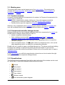
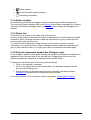
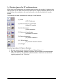
Help
© 2013 Vela Solaris AG | www.velasolaris.com
Table of contents
1
Getting started
4
2
Polysun menu bar
5
3
2.1
Project
2.1.1 Wizard
2.1.2 New project
2.1.3 Open project
2.1.4 Close project
2.1.5 Save project/Save project as
2.1.6 Rename project
2.1.7 Load photograph of property
2.1.8 Print
2.1.9 Close
6
6
6
7
7
7
7
7
7
7
2.2
Variant
2.2.1 Create new variant
2.2.2 Add template to project
2.2.3 Rename variant
2.2.4 Copy variant
2.2.5 Delete variant
2.2.6 Variant as reference
2.2.7 Comment on the variant
2.2.8 Save system diagram
2.2.9 Print system diagram
2.2.10
Zoom system diagram
8
8
8
8
8
8
8
9
9
9
9
2.3
Results
2.3.1 Results overview
2.3.2 Economic viability
2.3.3 System results
2.3.4 Component results
2.3.5 Tabular evaluation
2.3.6 Graphical evaluation
2.3.7 Fluid overview
2.3.8 PDF reports
10
10
10
11
11
11
11
12
12
2.4
Catalogues
2.4.1 View catalogue entries
2.4.2 Use catalogue entries
2.4.3 Create catalogue entries
2.4.4 Delete catalogue entries
2.4.5 Export catalogue entries
2.4.6 Import catalogue entries
13
13
13
13
14
14
14
2.5
Options
2.5.1 Settings
2.5.2 Add license
2.5.3 Subscription / Upgrade
2.5.4 Support and Help
2.5.5 Help
2.5.6 User manual
2.5.7 Support website
2.5.8 Support request
2.5.9 Info
15
15
15
15
15
16
16
16
16
16
Polysun main window (graphical user interface)
Polysun Help
Vela Solaris
17
2 / 32
3.1.1
3.1.2
3.1.3
3.2
4
Project overview
Location
Variants
17
18
18
Templates
19
3.3
Working area
3.3.1 System schemes
3.3.2 Component/controller dialogue boxes
3.3.3 Speedbuttons
3.3.4 Status window
3.3.5 Status line
3.3.6 Polysun component symbol bar (Designer only)
20
20
20
20
21
21
21
3.4
22
System planner for PV rooftop systems
Working with Designer
4.1.1 Edit system schemes
4.1.2 Add new components
4.1.3 Select components
4.1.4 Move or rotate components
4.1.5 Delete components
4.1.6 Connect components
4.1.7 Untie connections
4.1.8 Create system scheme from scratch
4.1.9 Particular features of given components
28
5
Print
30
6
Updater
31
7
FAQs
32
Polysun Help
Vela Solaris
28
28
28
28
28
28
29
29
29
3 / 32
1 Getting started
Welcome to Polysun!
This guide provides an overview of the main instructions to be followed to correctly
operate this program. Additional useful information can be found in the User manual
containing key technical background information; the FAQs appearing on the Vela
Solaris web site provide further guidance on the subject. For further information do not
hesitate to contact your distributor.
If you are working with Polysun for the first time we recommend you to use the provided
wizard which will guide you through the creation of a project from the selection of the
location and a suitable system to the entry of consumer values all the way to the first
simulation. Results available in different output formats are shown automatically.
Further relevant information can be found in the chapter describing the Results menu.
Finally the project may be further developed and edited in the Polysun main window.
This guide explains how components can be defined within system schemes and how
catalogues can be used. The User manual contains key technical background notes on
the subject.
Your Vela Solaris-Team wish you success in the use
of Polysun
Polysun Help
Vela Solaris
4 / 32
2 Polysun menu bar
The Polysun menu bar shows the following main menus: Project, Variant, Results
Catalogues, Options and ?; these are described in greater detail in the following pages.
Polysun Help
Vela Solaris
5 / 32
2.1 Project
A project includes all data required for a simulation. A project can be created, for
example, for a house for which the user defines a location and the relevant consumer
values creating, however, multiple system variants.
2.1.1 Wizard
The wizard is designed to guide the user through the process of creating a project with
a variant essentially matching his/her requirements. After the first simulation and the
first result analysis have been completed all settings may be adjusted directly on the
location page and in the component dialogue boxes.
Project
Define project name and location (select first region (continent), then country and finally
the location).
Should the desired location not appear in the list the software versions Professional and
above allow the user to set-up a new location.
Confirm selection with Continue.
Category
To select the required system category select Consumer and Energy Sources. Three
settings are available to this end:
(checkmark): only categories fulfilling the desired criterion are shown;
•
•
(cross): only categories not fulfilling the criterion are shown;
(dot): the criterion has no role in category selection.
•
Click the desired category (the image will be framed in red) and confirm with Continue.
Template
Select the desired template according to the same criteria as those used for category
selection.
Click the desired template (the image will be framed in red) and confirm with Continue.
Demand
Define values. The symbol refers to a catalogue. Click the entry shown next to it on
the right-hand side and select the desired catalogue entry.
Should the desired catalogue entry not appear in the list software versions Professional
and above allow the user to set-up a new entry. For further details see chapter Create
catalogue entries.
Confirm selection with Continue.
Setup/PV
Define values and catalogue entries as shown under Demand. Confirm with Accept.
Polysun carries out a first simulation. For further details see chapters Results and
Polysun main window.
2.1.2 New project
First step towards the creation of a project with no assistance from the Wizard. Name
project and confirm with OK.
Polysun Help
Vela Solaris
6 / 32
This command can be selected either from the Project menu or right-clicking the name
of an existing project. In the latter case the existing project will be closed. If the project
has not yet been saved Polysun will prompt the user to save the existing project.
2.1.3 Open project
This command allows the user to open Polysun projects in *.psp or *.pse format that
he/she created.
This command can be selected either from the Project menu or right-clicking the name
of a running project. In the latter case the running project will be closed. If the project
has not yet been saved Polysun will prompt the user to save the running project.
The software does not allow two projects to be opened at the same time. However the
user will be able to run two different Polysun installations in parallel on the same PC by
naming the relevant installation directories with different names. In this way the user will
be able to work on two projects at the same time.
2.1.4 Close project
This command can be selected either from the Project menu or right-clicking on the
project’s name.
Before unsaved Polysun projects are closed Polysun prompts the user to save the
project.
2.1.5 Save project/Save project as
This command can be selected either from the Project menu or right-clicking on the
project’s name.
This command allows the user to save Polysun projects as *.pse file.
2.1.6 Rename project
This command can be selected either from the Project menu or right-clicking on the
project’s name.
Rename project and confirm with OK.
2.1.7 Load photograph of property
Here the user can upload an external photograph available in *.jpg, *gif or *.png format.
The picture will then appear in the Project overview and in the PDF-Reports.
2.1.8 Print
The selected page will be shown as a PDF file (see chapter Print).
2.1.9 Close
This command allows the user to close Polysun.
Polysun Help
Vela Solaris
7 / 32
2.2 Variant
A variant is a system scheme which can be simulated through the settings available in
the dialogue boxes of the single components associated with other project data such as
location and consumer. A project may include any number of variants.
2.2.1 Create new variant
This function (available only in the Designer version) allows the user to create an
altogether new variant starting from a completely empty page. For further details see
chapter Working with Designer.
2.2.2 Add template to project
To add a template to a project select the desired template (highlight in pink) directly
from the template collection shown in the bottom left corner. After naming the variant
and confirming with OK the template becomes a new variant, i.e. is linked to other
specific data projects.
2.2.3 Rename variant
To do so select the variant (highlight in pink) that is to be re-named. Then two options
are provided:
a) Click on “Rename variant” in the Variant menu;
b) Right-click on variant name and select “Rename variant”.
In both cases enter new name and confirm with OK.
2.2.4 Copy variant
To do so select the variant (highlight in pink) that is to be copied. Then two options are
provided:
a) Click on “Copy variant” in the Variant menu;
b) Right-click on variant name and select “Copy variant”
In both cases enter name of copy and confirm with OK.
Tip: if two systems only differing in one or two settings are to be compared to one
another you may want to create first a new variant, copy it and finally only change the
desired settings in the copy. Simulation results can be thus compared meaningfully
being ensured that all remaining settings are equal.
2.2.5 Delete variant
To do so select the variant (highlight in pink) that is to be deleted. Then two options are
provided:
a) Click on “Delete variant” in the Variant menu;
b) Right-click on variant name and select “Delete variant”
In both cases confirm with Yes.
2.2.6 Variant as reference
A variant should be set as a reference if two variants are to be compared to one another
in a diagram. Proceed as follows:
• Select and copy a variant.
• Make changes in the component dialogue boxes of the new variant.
Polysun Help
Vela Solaris
8 / 32
•
Set a variant as a reference. To do so select the variant (highlight in pink) that is
to be set as a reference. Then two options are provided:
o Click on “Variant as reference” in the Variant menu
o Right-click on variant name and select “Variant as reference”
•
In the Result menu call-up the Result overview for the original blue-marked
variant. The variant is simulated.
Simulate the reference variant. Confirm the related message with OK.
The Result overview will be displayed together with two data sheets. Some of the
callable diagrams show both systems in comparison with one another.
•
•
Tip: it is always advisable that the more energetically unfavourable variant be set as a
reference.
The reference variant may be restored to a normal variant either by clicking again on
Variant as reference or selecting a different variant as a reference. In a project only one
variant may be set as a reference at the same time.
2.2.7 Comment on the variant
Here the user will be able to enter and confirm with OK a comment on the variant. This
comment will be shown on the Project overview page and in the PDF-Reports.
2.2.8 Save system diagram
The image of the system diagram referring to the selected (highlighted in pink) variant
can be saved as a *.png file.
2.2.9 Print system diagram
The system diagram referring to the selected (highlighted in pink) variant can be shown
as a PDF file. (see chapter Print).
2.2.10
Zoom system diagram
The system diagram of the selected (highlighted in pink) variant may be zoomed in or
out. You may want to zoom in on the system diagram in case of systems consisting of a
large number of components as basic settings will not allow them to be completely
shown on screen.
Tip: hold the Ctrl button pressed and roll the mouse wheel to zoom in or out.
Polysun Help
Vela Solaris
9 / 32
2.3 Results
Simulation results will be shown for the currently selected variant. Results may be
called-up either from the Results menu or clicking the
results) located on the upper part of the window.
button (Display selection of
Further information on the meaning of the single values can be found in the User
manual in the Simulation results chapter.
Attention: for the results to be displayed a variant must always be selected (highlighted
in pink). The user will then be able to call-up the desired view from the Results menu. If
since the last simulation data were edited or a dialogue box was opened and data were
confirmed with OK the software will repeat the simulation process for the variant. If no
data were edited or newly confirmed the results will be displayed directly.
If the system was incorrectly defined error messages will be displayed either during or
after the simulation. The message Energy demand not met indicates that the calculated
energy demand is not met in a considerable number of steps, i.e. the system cannot
often rely on the amount of energy required to meet the calculated demand. A detailed
analysis of component results will cue the user in on the possible source of error. In
most cases components turn out to have incorrect settings. Tip: review settings in the
templates and compare them with your settings. For further details see the User manual
in the chapter “Controllers”.
The results may be displayed in different formats. Depending on the different user levels
not all tables and graphs are available.
The following applies for all result display formats: click the
button (Print) to display
a PDF file (see chapter Print). Click the
button (Export results) to save results as a
*txt file.
Tip: selecting the heading of the respective data sheet (the data sheet title will be
framed in red) and pressing the Ctrl and C buttons results will be copied to the
clipboard; from there they may be later entered in a different program such as Microsoft
Excel.
2.3.1 Results overview
The results overview enables the user to get a first idea whether or not the system was
correctly defined. Only the most significant results are displayed; annual values are
presented in a tabular format. The values appearing in the selected lines are displayed
down below as a bar graph.
The result overview takes on a particular meaning if two systems appearing in a
diagram are to be compared with one another. To this end set a variant as reference.
2.3.2 Economic viability
In the upper tables economic viability is divided depending on the different energy
types. In each table purchasing and maintenance costs, fuel costs, incentives and other
values can be defined separately. After they are entered results are recalculated in the
Polysun Help
Vela Solaris
10 / 32
bottom part of the screen. A result overview as well as a report showing more detailed
information are displayed on screen.
Exiting the economic viability function by pressing OK all settings are stored with the
variant. In addition settings for new variants can be saved as preset values.
2.3.3 System results
Here the monthly values referring to the entire system and the single current and fluid
loops are displayed both in tabular format and as a bar graph. This display provides the
user with an excellent overview of the most significant values.
2.3.4 Component results
Here the monthly values referring to the single components are displayed both in
tabular format and as a bar graph (always the values included in the lines selected
within the table). This view proves very useful in analysing the functionality of the
different components and searching possible sources of error.
2.3.5 Tabular evaluation
This comprehensive table (available only in the Designer version) displays the hourly
values of all components.
Tip: clicking on the
button (Display selection window) a folder for the single
components will be displayed. Double-click on the desired components. Finally select a
value e confirm with OK. The table shows the corresponding columns.
2.3.6 Graphical evaluation
This function enables a detailed and customised graphical evaluation of simulation
results to be displayed. Proceed as follows:
• Select week or month.
• Click button „Add curve“.
• A window showing the folder tree for the single components is displayed. Doubleclick on the desired components. Finally select a value and confirm with OK.
• A curve showing the hourly values referring to the components selected for the
indicated period is displayed.
• Further curves can be added for data comparison purposes.
• Selected curves (highlighted in pink) may be deleted with button “Delete curve”.
Shift curves and optimize scaling
Using the
and
buttons the user will be able to shift curves and optimize the
scaling. Tip: vertically improve scaling if curves run over the lower edge of the graph.
Week or month
The shorter the selected period, the more precise will be the graphical representation of
hourly values. The software is unable to display a detailed annual curve as the graph
does not have enough pixels to display all values.
Tip: zoom in on the graph to gain even more insightful data. To do so hold the left
mouse-button pressed and draw a square over a portion of the curve from the top left
corner to the bottom right corner and release the mouse button.
Units and axes
Polysun Help
Vela Solaris
11 / 32
The graph has two vertical axes. This allows curves with up to two different units to be
meaningfully compared with one another. The respective reference axis may be
in the Axis column .
changed by clicking
Colours and lines
The user will be able to customise the graph choosing from a wide range of colours and
lines. Colours ad lines can be edited with a simple click.
Save graph
Clicking the
button (Save graph) the selected graph can be saved as a *.png file.
2.3.7 Fluid overview
The folder tree displayed by selecting this view shows which heat transfer fluid flows
through which loop and the components the relevant loops consist of.
The fluid can be changed with the
button (Change heat transfer fluid).
2.3.8 PDF reports
Different PDF reports differing in level of detail are available depending on user level
(see chapter Print).
These reports provide an ideal tool to present results to customers. Reports should be
created only when the user is satisfied with simulation results and has already reviewed
them in the other available output formats.
Polysun Help
Vela Solaris
12 / 32
2.4 Catalogues
Polysun provides for all system components separate catalogues (databases) in which
products are listed in tabular format together with the relevant specific data. Catalogues
include both anonymous component examples as well as products available on the
market for which an indication of the manufacturer or the testing institute is provided.
2.4.1 View catalogue entries
Catalogues can be viewed either directly from the Catalogues menu or through the
component dialogue box. The symbol refers to catalogues: double-clicking on the
product name appearing next to the symbol will open the related catalogue.
Many catalogues are hierarchically sorted; i.e. they contain sub-catalogues marked with
the symbol.
Tip: pausing with the mouse on a given column tool tips will be displayed providing
useful information on the respective values. Column width can be adjusted using the
mouse in the header.
Depending on the different user level not all catalogues are available.
2.4.2 Use catalogue entries
Catalogue entries may be only used by means of the respective component dialogue
boxes. Should a product be replaced with another in a variant the relevant component
of the existing variant should be double-clicked in the working area. A dialogue box will
open. Proceed then as follows:
• The symbol refers to the existing catalogues. Double-click the product name
appearing next to it to open the corresponding catalogue.
• Select the desired product. The selected line is highlighted in pink.
• Confirm with Accept.
• The catalogue shuts down and the selected product is displayed in the dialogue
box. Adjust further settings if required.
• Confirm settings with OK. The dialogue box shuts down.
Tip: the desired catalogue entries can be found more rapidly using a filter. Clicking the
blue header the values appearing in the relevant columns are sorted alphabetically and
numerically. This makes catalogue reading easier. Attention: the sorting process will
take a few seconds to complete in case of particularly large catalogues (e.g. location
catalogue).
2.4.3 Create catalogue entries
The function is only available for software versions Professional and above. The
creation of new catalogue entries will essentially require the amendment of existing
catalogues. Tip: it will be helpful to search for and amend an entry that is closest to the
one you wish to create.
• Select an existing entry. The selected line is highlighted in pink.
• Copy the selected line with the
button (Copy selected line).
• Enter a name for the new catalogue entry. Confirm with OK.
• Enable the copied line to be edited by pressing the
The relevant line should appear in red.
Polysun Help
Vela Solaris
button (Edit selected line).
13 / 32
• Make changes directly in the relevant fields and confirm either with the Enter button
or with Accept.
2.4.4 Delete catalogue entries
The user will be able to delete only catalogue entries he/she previously defined. To do
so proceed as follows:
• Select an entry you previously created. The selected line will be highlighted in
pink.
•
•
Click the
button (Delete selected line).
Answer the “Should the selected line be deleted?” question with Yes.
2.4.5 Export catalogue entries
Software versions Professional and above allow catalogue entries to be exported to be
made available to other users:
• Select an entry. The selected line will be highlighted in pink.
• Click the
button (Export selected line).
• Name and save the file as a *.psc file in the desired directory.
The file can be later sent via e-mail and imported by a different user.
Tip: it is always advisable to export the whole project. This allows all user-defined
components to be automatically saved and to be stored in the relevant catalogues in
case the project is imported.
2.4.6 Import catalogue entries
Software versions Professional and above allow catalogue entries to be imported by
other users:
• Click the
button (Import selected line).
• Select the relevant *.psc file. Beware that the selected *.psc file contains a variant
included in the open catalogue.
• Confirm selection with Open.
Polysun Help
Vela Solaris
14 / 32
2.5 Options
2.5.1 Settings
Project
Here the user will be able to decide whether (after it is started) Polysun should
automatically open the wizard, the latest project or a standard project. A standard
project can be selected by clicking on the
button.
Simulation
Should the reference variant be simulated upon confirmation, without confirmation or
never be simulated?
The preliminary simulation ensures that on simulation start (January 1st ) a realistic
situation is provided, the system has already been run in and it was not only put into
operation at the turn of the year.
Reports
PDF-Reports will show the entered company name, e-mail address and telephone
number as well as name and address of license holder. Clicking the
button you may
select your own company logo that will likewise appear in the PDF-Reports. In case of
relocation the license holder’s address can be changed collecting the license again (see
paragraph Add license).
Display
A variety of settings can be adjusted here including the automatic search for updates,
the display of Tool Tips, language, units and currency.
2.5.2 Add license
Should a license be added or renewed, e.g after your Polysun subscription has been
renewed, user-ID and e-mail address should be entered here like when the license was
first released. Review your information for accuracy on the ensuing page. It is important
that the entered information is correct as it will appear on all reports and your license
will be registered using such information. Collect your license again and edit your
information if you have relocated or changed your e-mail address.
A working Internet connection is required to collect the license. Ensure that the same
network cards are always activated (possibly not a wireless network-card) when
collecting your license and operating Polysun.
2.5.3 Subscription / Upgrade
If your Polysun subscription has expired or your wish to upgrade your Polysun (e.g from
Professional to Designer) here you will be able to order all required products. Do not
hesitate to contact your distributor any time. When your subscription has been renewed
you can renew your license under Add license.
2.5.4 Support and Help
This chapter covers the ? menu.
Polysun Help
Vela Solaris
15 / 32
2.5.5 Help
The file you are reading provides you with essential support in the use of your Polysun.
The Table of contents affords you an useful overview of the structure of this guide.
Useful technical background information is provided in the User manual.
2.5.6 User manual
The User manual contains important technical background information on Polysun.
Information and practical tips on the use of the program are provided in this guide.
2.5.7 Support website
This link takes you to the website of Vela Solaris where you will be able to find an
answer to the most frequently asked questions on Polysun (FAQ Frequently Asked
Questions).
2.5.8 Support request
Should you not find an answer to your questions in this Guide, in the User manual or in
the FAQ your distributor will be delighted to help you find a solution. In this dialogue box
you can read your distributor’s contact information as well as your user number (UserID); you should provide this information for each request.
Click the
button (Create support file) to create a support file to assist your distributor
in finding out a solution to your problem. After clicking the button a message shows you
the directory path where the file was stored.
2.5.9 Info
Here you will find information on the copyright and the different Polysun partners. Your
information is stored under License. Should you forget your user-ID you will be able to
read it here anytime.
Polysun Help
Vela Solaris
16 / 32
3 Polysun main window (graphical user interface)
Polysun’s graphical user interface is essentially divided into three parts: on the top left
are the project data, on the bottom left is the template collection; the working area is on
the right-hand side. The parting lines between the above areas can be easily moved
using your mouse so that the main window can be adjusted to fit the needs of all users.
1.
2.
3.
4.
5.
6.
7.
Menu bar
Toolbar
Project data (folder tree)
Working area
Template collection
Status window
Status line
3.1.1 Project overview
Photograph of property
Right-clicking on the field in the top left corner you will call-up the “Load photograph of
property” command. Confirm with the left mouse-button to upload external photographs
available in *.jpg, *gif or *.png format. To delete a picture from the project overview
right-click on it and select “Remove photograph”.
Polysun Help
Vela Solaris
17 / 32
Comments on the project
Here you will be able to enter comments that are of some interest for the relevant
project.
Variants
This field contains a list of the variants you already created. Selecting a variant
(highlighted in blue) the comments you entered on the variant appear in the field on the
bottom right. These can be edited from the Variant menu (Comment on the variant).
3.1.2 Location
Location
A location may be either selected from the database or found on ”openstreetmaps.com”.
This will require an active Internet connection.
Weather data
Clicking on “from location” the weather data referring to the selected location will be
calculated according to Meteotest.
Clicking on “from file“ the data of a file will be extracted together with hourly values
saved in the application folder of the Polysun installation. For further information please
open the catalogue “Profile”.
Tip: by typing in the first letter of the desired location name in the location selection list
the software will automatically go to the first location name starting with the typed in
letter. Typing then the remaining letters of the name the software will search for the
location name that comes closest to the entered sequence.
Cold water supply and storage room
Tool Tips provide an explanation for the single terms. The
that may be opened by clicking on the relevant data entry.
symbol refers to catalogues
Horizon
Use the slide controls to display a graphical representation of the position of the sun for
the selected location for every hour and day of the year. The yellow curve represents
the solar ecliptic on the selected day. The red line is the horizon that can be drawn in
the chart by clicking the graph or entering the exact horizon points. Tip: multiple values
(separated by a semi-colon) may be added from the clipboard directly to the table using
the Ctrl-C buttons.
3.1.3 Variants
Here a list is displayed of all project variants. The variant currently selected (highlighted
in pink) will be displayed in the working area.
For further details on how to create variants see chapter Variant (Polysun menu bar).
Polysun Help
Vela Solaris
18 / 32
3.2 Templates
Polysun’s template collection is shown in the main window’s bottom left portion.
Depending on the user level not all templates are available.
A template is a system scheme that becomes a variant and may be therefore simulated
only after being copied to a project.
Templates are divided into three main groups (Vela Solaris, Special, Companies),
consecutively numbered and sorted by category. Dragging your mouse over the list you
will get a preview of the available system schemes. Templates may be directly selected
off the list and copied to a project. Clicking them and confirming the related message
(see also chapter Variant, paragraph Add template to project).
Tip: use the wizard to make your search for the desired template easier.
Polysun Help
Vela Solaris
19 / 32
3.3 Working area
The working area takes up the largest part of the main window. The working area
includes the Project overview, the location page as well as the system schemes of
templates and variants.
3.3.1 System schemes
A system scheme displays all components of a system. In Polysun all components of a
variant may be clicked on:
• Select a component by simply clicking on it; four dots appear around the
component to confirm the selection (see also Working with Designer);
• Double-click to open the respective component dialogue box.
Attention: only components with a variant may be opened. Clicking on a template the
user will be asked whether the template should be added to the project.
3.3.2 Component/controller dialogue boxes
Dialogue boxes are the input windows displayed when the components of a variant are
double-clicked. Dialogue boxes allow the user to:
• Adjust component-related settings;
• Open catalogues and possibly use other catalogue entries or create new
catalogue entries for the respective components. The symbol refers to a
catalogue. Double-click on the catalogue entry appearing next to it to open the
relevant catalogue.
• Open a dropdown-menu. The symbol refers to a dropdown-menu: click on the
name appearing next to it to open the corresponding selection.
Double-click on a control to open a modified dialogue box. The above mentioned editing
functions are available. A special time profile can also be loaded. To this end the
availability times profile should be activated. Double-click on the profile name to open a
catalogue menu
In the User manual you will find comprehensive instructions on how to select the right
settings in the different component dialogue boxes.
3.3.3 Speedbuttons
The following buttons appearing (from left to right) at the top of the window can be used
as ”quick links“ to call-up the different features from the menu:
•
Wizard
•
New project
•
Save project
•
Open project
•
Copy variant
•
Rename variant
•
Save schematic system diagram
Polysun Help
Vela Solaris
20 / 32
•
Delete variant
•
Zoom schematic system diagram
•
Preliminary simulation
3.3.4 Status window
All simulation procedures are logged in the field appearing under the working area.
The command Copy message area in the Options menu allows messages to be copied.
The command Delete message areas in the Options menu allows al messages to be
deleted.
3.3.5 Status line
The status line is shown on the lower end of the window.
As soon as the project is saved the file name is displayed on the left-hand side in black
characters. After a change has been made the characters turn grey to show that the
current project was not yet saved.
If a variant was simulated the energy demand on the system is shown in black
characters on the right-hand side. After a change has been made the characters turn
grey to show that the value is no longer up-to-date and should be simulated again.
3.3.6 Polysun component symbol bar (Designer only)
In the Designer version a vertical bar showing the symbols of all system components is
displayed on the left-hand side of the working area. Dragging the mouse over the
different symbols the respective component names will be shown.
Components can be placed in the working area as follows:
• Click on the desired component.
• Click on the design area in the working area. The desired component will be
placed in the working area.
• Double-clicking on the component previously placed in the working area a
dialogue box opens and the components can be edited.
For further details on how to create a variant see chapter Working with Designer.
Polysun Help
Vela Solaris
21 / 32
3.4 System planner for PV rooftop systems
While user level Professional only enables users to enter the number of modules they
wish to place in a PV field, but not to edit their layout, Polysun Designer allows you to
actually place the modules on the roof surface so as to view the layout of inverter
strings.
The planning tool was expanded with a range of new features
(1) Arrow
(2) PV Catalogue
(3) Add and edit roof coordinates
(4) Add PV module
(5) Add dimensions
(6) Add obstacles
(7) Delete roof coordinates
(8) Delete PV module
(9) Delete dimensions
(10) Delete obstacles
(11) 3D roof-view
(12) Inverter allocation wizard
(13) Designs
Standard procedure in Polysun Designer
1. Open a new project by selecting “Project“/“Open Project…”
2. The “50a: Photovoltaik“ system is imported into the project from the template
folder. On delivery, the template is bookmarked as a favourite so that it will
regularly appear in the “Favorites”.
Polysun Help
Vela Solaris
22 / 32
3. In the “50a: Photovoltaik“ variant, from user level Professional the project tree
includes an additional entry for the roof surface. With a right mouse click, the roof
surface can be named as you wish.
4. Clicking on the “Add and edit roof coordinates“ (3) button, the key parameters of
the roof may be set or edited. The button also enables the user to enter the basic
details of the roof.
To set new coordinate points, simply click with the mouse on the roof edge line;
click and drag the coordinate points to move them. If you have a point selected,
you can move it also by entering the coordinates as a numerical value in the
fields appearing above the roof plan.
Polysun Help
Vela Solaris
23 / 32
5. Button (6) enables the user to place obstacles on the roof surface; to select the
different types of obstacles proceed as follows
The selected obstacle can then be placed on the roof surface with the mouse.
Using the “arrow“ button (1), obstacles can be clicked and altered in detail.
6. The “Open PV module catalogue“ button (2) enables the user to select a specific
PV module from the Polysun catalogue.
7. The user can view the different options available to add a module on the roof
surface by clicking the “Place PV module“ button. According to the selection,
modules are placed on the roof arranged in a serpentine pattern.
Polysun Help
Vela Solaris
24 / 32
8. To access the inverter design tool, click on the “Inverter wizard“ button (12); the
number of modules will be imported from the previous automatic placement.
9. After closing the “Inverter wizard, the different design variants are shown in a
window. Strings are numbered both in the design variants and in the roof plan.
By clicking on a string with the mouse, this will be marked in blue in the roof plan.
Polysun Help
Vela Solaris
25 / 32
10. String allocation can be modified by clicking on the relevant PV module in the
roof plan. Clicking on an already marked PV module, this will be released from
the current string. Clicking once a module from a different string, this will be
removed from it and, by clicking again, it will be imported into the marked string.
If the arrangement in the design variant does not match that in the roof plan, the
relevant strings will be marked in red in the design variant overview.
The user is constantly shown how many modules are currently allocated to the
string and the number of modules that should be allocated to it. The manual
string allocation is through when all strings are shown with a green check-mark
next to them.
11. The PV yield calculation can be started and graphically presented by selecting
the appropriate entries from the ”Results“ drop-down menu.
In the PDF report, the string allocation is printed out in roof plan format.
Polysun Help
Vela Solaris
26 / 32
If different PV fields appear on the Polysun design area, roofs are displayed each in a
separate planning tool where they can be individually edited.
Strings may not be dragged over different roofs. If roofs have a different pitch and
orientation, strings distributed over different roofs would result in a considerable loss in
yield; for this reason, in Polysun such a possibility is ruled out a priori.
Polysun Help
Vela Solaris
27 / 32
4 Working with Designer
The Designer version allows system schemes of existing variants to be edited and
enables the user to the create altogether new system schemes.
4.1.1 Edit system schemes
To do so the user should start from an existing template that he/she will add to the
project as a variant (see Add template to project). The user can then delete components
of the variant, add new components, connect components to one another and untie
existing connections.
4.1.2 Add new components
•
•
•
Click the desired component in the component symbol bar.
Click on the design area in the working area. The desired component will be
placed in the working area.
Double-click on the component you previously placed in the working area; a
dialogue box opens and components can then be edited.
4.1.3 Select components
Select a component by simply clicking on it; four dots appear around the component to
confirm the selection. To select multiple components keep the Shift button pressed;
select all components using the Ctrl-A buttons.
4.1.4 Move or rotate components
A previously selected component can be moved on the design area dragging it while
holding the left mouse-button pressed. Keep the Ctrl button pressed to move the
selected elements using the arrow buttons. Right-click on an element to display
additional functions to adjust or rotate it.
4.1.5 Delete components
•
•
•
Select a component by simply clicking on it; four dots appear around the
component to confirm the selection;
Right-click on the selected component;
Select Delete from the selection window – the component will be deleted.
4.1.6 Connect components
•
Click on the square connection of a component. The connection will be marked in
red.
• Click on the connection of a different component. The two components will be
connected.
Tip: if connecting two components that can only be joined by means of a pipe Polysun
automatically displays the required pipe. This allows the user to design large systems in
a time-saving and efficient manner. – To add a curve click on a given point of a pipe
while holding the left mouse-button pressed.
Polysun Help
Vela Solaris
28 / 32
4.1.7 Untie connections
Double-click on existing connections (black dots) to untie them.
4.1.8 Create system scheme from scratch
The command Create new variant in the variant menu enables the user to create a
variant from scratch starting with an empty page. Components can be added and
connected as described above.
Tip: it is advisable to begin by editing existing variants and reviewing default settings.
The user should proceed step by step and carry out frequent simulations to better
understand how changes are made.
4.1.9 Particular features of given components
•
•
•
•
Tank: if you wish to place a new tank you can choose between “Define a new
tank” and “Choose a tank from the catalogue”. This last option involves the
selection of an existing tank from the catalogue. Choosing “Define a new tank” a
new window opens in which the tank can be configured. First the basic structure
of the tank is defined. After confirming with OK the tank is displayed on the
design area. Finally the tank can be further edited by double-clicking on it (see
Polysun dialogue boxes and catalogues).
Deleting a tank the temperature sensors are also deleted. When a new tank is
placed the temperature sensors should be reset in the relevant controllers, i.e.
the entries should be redefined.
Controllers: when placing a controller the user should select the most suitable
one. Here too it is advisable to take a cue from the default settings of the
templates.
Heat generator: boiler or heat pump, with or without integrated pump. Please
ensure a flow-rate generator is available in the relevant loop.
Read by all means the comprehensive instructions on single components and
controllers provided in the User manual.
Polysun Help
Vela Solaris
29 / 32
5 Print
The program enables the user to print the different pages of the working area, all
dialogue boxes and all results. Click the
be later saved or printed.
button (Print) to display a PDF file that can
To display the PDF files you will need a free Adobe Acrobat Reader. For further details
on this product see the www.adobe.com website.
Respect the environment, only print PDF files when strictly required.
Polysun Help
Vela Solaris
30 / 32
6 Updater
Polysun is regularly updated. Updates do not only refer to catalogue data but also to
software functionalities that are constantly extended. It is therefore advisable to always
keep your Polysun updated to the latest version.
Users are entitled to free updates if they first picked-up their license or their latest
subscription expired less than twelve months before. If your license has expired you will
be informed by an appropriate message. Renew your subscription or contact your
distributor.
Choosing Look for updates in the first line (after Polysun has been started) under
Display in the settings of the Options menu Polysun automatically checks for updates
on the server. All you need is a working Internet connection.
If an update is available a message is displayed to inform the user. Proceed as follows:
• Close Polysun.
• Start the Polysun-Updater. To this end open the Program menu on your
computer and look up Polysun. Select Polysun; a window will be displayed to its
right with the following options: Deinstall Polysun – Polysun (to start the program)
– Polysun Updater. Select the updater.
• Ensure a stable Internet connection is available.
• The Updater shows which updates are available. Click on Continue to download
and automatically install the update.
• Finally click on Close to close the Polysun-Updater.
• Re-start Polysun. To see which version is currently installed check the start
window.
For further questions do not hesitate to contact your distributor.
Polysun Help
Vela Solaris
31 / 32
7 FAQs
For constantly updated questions and answers on Polysun check the website
http://www.polysun.ch/polysun.php?id=ps_faq.
Polysun Help
Vela Solaris
32 / 32