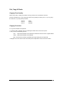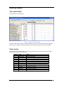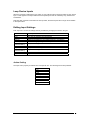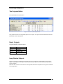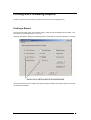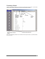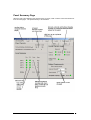
1
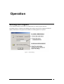
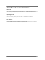
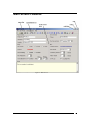
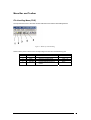
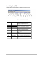
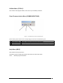
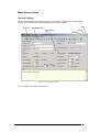
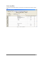
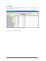
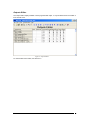
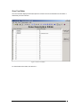
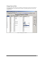
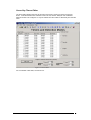
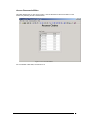
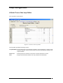
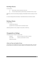
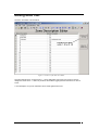
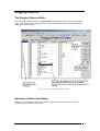
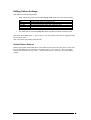
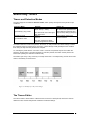
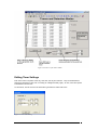
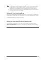
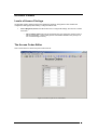
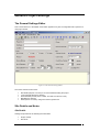
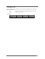
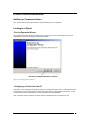
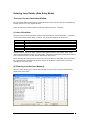
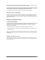
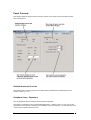
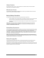
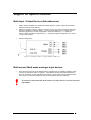
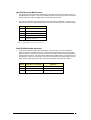
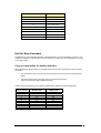
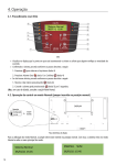
Dimension 2.0
Document No. 996-151 Issue 2
User Manual
1
Introduction
4
Notice ........................................................................................................................................ 4
Warnings and Cautions.............................................................................................................. 4
National Approvals.................................................................................................................... 4
Description
5
PC Requirements ....................................................................................................................... 5
Operation
6
Starting the Program.................................................................................................................. 6
Opening a File / Creating a New File ........................................................................................ 7
New File ...................................................................................................................... 7
Opening a File ............................................................................................................. 7
File History.................................................................................................................. 7
Main Screen Features ................................................................................................................ 8
Menu Bar and Toolbar ................................................................................................ 9
Main Screen Views ................................................................................................... 12
Loop Configuration ................................................................................................................. 20
A Quick Tour of the Loop Editor .............................................................................. 20
Inserting a Device...................................................................................................... 21
Deleting a Device ...................................................................................................... 21
Changing Device Settings ......................................................................................... 21
Cut, Copy & Paste ..................................................................................................... 22
Editing Inputs .......................................................................................................................... 23
The Inputs Editor....................................................................................................... 23
Panel Inputs ............................................................................................................... 23
Loop Device Inputs ................................................................................................... 24
Editing Input Settings................................................................................................ 24
Editing Outputs........................................................................................................................ 25
The Outputs Editor .................................................................................................... 25
Panel Outputs ............................................................................................................ 25
Loop Device Outputs................................................................................................. 25
Editing Output Settings ............................................................................................. 26
Editing Zone Text.................................................................................................................... 27
Ringing Patterns ...................................................................................................................... 28
The Ringing Patterns Editor ...................................................................................... 28
Selecting a Pattern for Editing................................................................................... 28
Editing Pattern Settings ............................................................................................. 29
Seven-Day Timers ................................................................................................................... 30
Timers and Detection Modes..................................................................................... 30
The Timers Editor ..................................................................................................... 30
Editing Timer Settings............................................................................................... 31
Setting the Timer Detection Mode ............................................................................ 32
Setting the Delayed and Verification Mode Times ................................................... 32
Access Codes........................................................................................................................... 33
Levels of Access Privilege ........................................................................................ 33
The Access Codes Editor .......................................................................................... 33
Editing and Testing User Access Codes.................................................................... 34
General Project Settings .......................................................................................................... 35
The General Settings Editor ...................................................................................... 35
Site Details and Notes ............................................................................................... 35
Device Loop Details.................................................................................................. 36
Miscellaneous Settings .............................................................................................. 36
Saving a File ............................................................................................................................ 38
Panel Communications ............................................................................................................ 39
Setting up Communications ...................................................................................... 39
2
Linking to a Panel ..................................................................................................... 39
Printing and Previewing Reports ............................................................................................. 41
Printing a Report ....................................................................................................... 41
Previewing a Report .................................................................................................. 42
Loop and Battery Calculator.................................................................................................... 43
Overview ................................................................................................................... 43
Panel Summary Page................................................................................................. 44
Loop Voltage Drop Calculation ................................................................................ 46
Entering Loop Details (Data Entry Mode) ................................................................ 49
Isolators and Startup Current..................................................................................... 50
Panel Currents ........................................................................................................... 51
Backup Battery Calculation....................................................................................... 52
Support for Specific Devices ................................................................................................... 53
Multi-Input / Output Devices (Sub-addresses) .......................................................... 53
Multi-sensor/ Multi-mode analogue input devices .................................................... 53
Hochiki Base Sounders ............................................................................................. 56
3
Introduction
Notice
•
The material and instructions covered in this manual have been carefully checked for
accuracy and are presumed to be correct. However, the manufacturer assumes no
responsibility for inaccuracies and reserves the right to modify and revise this
document without notice.
•
These instructions cover the use and operation of the Dimension Panel Windows
Configuration Tool. Refer to the Fire Alarm Control Panel Product Manual (P/N 996-147-001)
for information on setting up the Fire Panel to be programmed using the Configuration
Tool.
Warnings and Cautions
These instructions contain procedures to follow in order to avoid injury and damage to
equipment. It is assumed that the user of this manual has been suitably trained and is
familiar with the relevant regulations.
All equipment is to be operated in accordance with the appropriate standards applicable
National Approvals
This equipment must be installed and operated in accordance with these instructions and the
appropriate national, regional and local regulations specific to the country and location of the
installation. Consult with the appropriate Authority Having Jurisdiction (AHJ) for confirmation
of the requirements.
EN54-2 13.7
EN54
!
Maximum of 512
sensors /
manual call
points per
panel.
The Dimension range of panels has many features, which if used
inappropriately, may contravene the requirements of EN54. Where
such a possibility may arise, a suitable warning is given with brief
details of the EN54 requirement and the relevant section it pertains
to. A typical EN54 non-compliance warning is illustrated.
4
Description
PC Requirements
The program requires the following specification or better: Pentium 166MHz
Windows 95 (OSR 2), 98, NT 4.x, Me, 2000 or XP.
32Mbyte RAM
10Mbyte free hard disk space
The PC should be configured for operation with a monitor resolution of at least 640*480 and 8-bit colour
mode.
5
Operation
Starting the Program
On the Windows desktop, double click on the Dimension icon and the program will start.
The display will show a splash screen displaying the company logo, then the following window will
appear, which allows a new project to be created or an existing project to be opened.
Figure 1 Startup Dialog
6
Opening a File / Creating a New File
New File
A new file can be created by selecting new from the toolbar or from the file menu. After this operation, it
will be necessary to specify the loop protocol that will be used. This cannot be changed once set.
Opening a File
A file can be opened by selecting open on the toolbar or alternatively from the file menu.
File History
The program keeps a list of the 5 most recently used files, which can be accessed from the file menu.
The list is updated and reordered each time a file is opened or saved.
7
Main Screen Features
Figure 2 Main Screen
8
Menu Bar and Toolbar
File Handling Menu (FILE)
The top left-hand corner of the main window holds the menus and the file handling buttons:
Figure 3 Buttons for File Handling
These buttons (each of which has a corresponding menu item and accelerator key) are:
No.
1
2
3
4
5
Name
New
Open
Save
Print
Preview
Function
Create a new file
Open an existing file
Save the current project
Print all or part of data
Preview the print layout on
screen
Keystroke
<Ctrl> + N
<Ctrl> + O
<Ctrl> + S
<Ctrl> + P
None
9
Data Editing Menu (EDIT)
This menu allows the navigation between the different editor screens. These are:
Figure 4 Speedbuttons for Data Editing
Item No
1–4
Menu Item
Main loops
5
6
7
8
9
Cut
Copy
Paste
Zone text
Inputs
10
Outputs
11
Ringing Patterns
12
7-Day Timers
13
14
Access codes
General settings
Description
Displays a sub-menu of active loops (up to a
maximum of 4). Allows devices to be
inserted into a loop, deleted, or have settings
changed
Used in the Device Loop editor to cut, copy
and paste devices between addresses
Edits textual description of any zone
Displays the inputs associated with the panel
and with loop devices, and allows the
properties of each input to be edited
As with the Inputs editor, but for panel and
device outputs
Edits the response mode for each zone in a
pattern
Edits the time bands for each of 14 timers,
and allows the timer detection mode to be
changed
Allows up to 10 user access codes to be set
Allows miscellaneous panel properties and
project details to be edited, and comments to
be entered
10
Utilities Menu (TOOLS)
This contains useful program utilities, such as the Loop and Battery Calculator.
Panel Communication Menu (COMMUNICATIONS)
Figure 5 Speedbuttons for Panel Coomunication
These buttons (each of which has a corresponding menu item and accelerator key) are:
1
2
3
Name
Config PCÆPanel
Config PanelÆPC
Comms Setup
Description
Send the configuration data from the PC to the panel
Send the panel’s configuration data to PC (overwriting the existing PC data)
Allows the communications port to be specified
Help Menu (HELP)
This contains two drop-down items:
User Manual: opens a Help system (which is this manual in HTML Help format)
About…. : standard program information
11
Main Screen Views
General Settings
This is the default screen which appears whenever a new project is created or a configuration file is
opened. It also appears when the General Settings menu item is selected.
Figure 6 General Settings Editor
For more details of this editor, see Section 4.11.
12
Device Loop Editor
The device loop editor displays details for one device loop, and is selected from the toolbar or the Edit
menu.
Figure 7 Device Loop Editor
13
Inputs Editor
The Inputs editor displays details for each programmable input. It can be selected from the toolbar or
from the Edit menu.
Figure 8 Inputs Editor
For more details of this editor, see Section 4.5
14
Outputs Editor
The outputs editor displays details of each programmable output. It may be selected from the toolbar or
from the Edit menu.
Figure 9 Outputs Editor
For more details of this editor, see Section 4.6
15
Zone Text Editor
The zone text editor displays textual descriptions for all zones and can be selected from the toolbar or
alternatively from the Edit menu.
Figure 10 Zone Text Editor
For more details of this editor, see Section 4.7.
16
Ringing Patterns Editor
The ringing patterns editor displays the complete list of ringing patterns and the full zonal settings for
one highlighted pattern, and is selected from the toolbar, or by selecting Edit in the menu bar, then
Ringing Patterns.
Figure 11 Ringing Patterns Editor
17
Seven-Day Timers Editor
The timers editor displays the start day and time and end day and time for each of the panel’s
timers. It also allows the timers’ detection mode to be set, and the “Delayed” and “Verification”
detection modes to be configured. It may be selected from the toolbar or alternatively from the Edit
menu.
Figure 12 Timers Editor
For more details of this editor, see Section 4.9.
18
Access Passwords Editor
This editor displays the 10 user access codes. It can be selected from the Access button on the
toolbar or by selecting Access in the Edit menu.
Figure 13 Access Codes Editor
For more details of this editor, see Section 4.10.
19
Loop Configuration
A Quick Tour of the Loop Editor
The Loop editor is shown below: -
Figure 14 Features of the Loop Editor
The loop editor provides the following controls: Loop Edit Mode: The loop edit mode can be used when inserting or removing devices. Once the mode
has been selected, a device can be inserted or removed by double left clicking on the
required address.
Device List:
The drop down list of devices can be used to choose which device to insert.
Grid:
The grid shows the basic details of each loop address and sub address.
20
Inserting a Device
To insert a device:
(1)
Select the type of device required in the device list.
(2)
Insert at the desired address by double-clicking on the address column in the grid
Alternatively, a device can be inserted by navigating to desired address and then pressing the <Insert>
key.
If a device is already present at the address, it will be deleted before the new device is inserted.
Deleting a Device
To delete a device:
(1) Select “Remove devices”
(2) Double-click in the address column of the address required.
Alternatively (without the mouse), navigate to it and press the <Delete> key.
Changing Device Settings
Settings which may be changed for a device include:
Description
(this can be entered even if there is no device).
Zone number
(Can be any value between 1 and 80)
Isolation group number
A Note on Zone and Isolation Group
A device which is not sub addressed has only one “Zone” and “Isolation Group” setting. This means
that if the device has one input and one output per address, then the settings are common for both.
21
Cut, Copy & Paste
Copying Functionality
Within a loop editor, a facility is provided to cut/copy a device from one address to another.
The three operations (Cut, Copy, Paste) are carried out by clicking on buttons (see 4.3.1.2) or by using
the edit menu, or by using the key shortcuts
<Ctrl>+X
<Ctrl>+C
<Ctrl>+V
(CUT)
(COPY)
(PASTE)
Copying Procedure
To copy device details to the clipboard:
1. In the loop editor, navigate to the row containing the details of the device to be copied.
2. Carry out one of the following actions: CUT:
Copies device details to the clipboard and deletes the device from the original address
COPY: Copies device details to the clipboard
Note: These actions overwrite any details which might already be in the clipboard.
3. Navigate to the new device location and select paste to duplicate the device at the new location.
22
Editing Inputs
The Inputs Editor
The Inputs editor is shown below: -
Figure 15 Features of the Inputs Editor
The inputs editor can be used to configure the settings for each input of the panel and its loop devices.
Inputs cannot be inserted or deleted in this editor and are listed according to the loop configuration.
Panel Inputs
The panel itself has 14 inputs which are not part of any device loop. There are 9 “panel state” inputs,
and a further 5 monitored onboard inputs.
Input No
1
2
3
4
5
6
7
8
9
10
11
12
13
14
Type
Panel state
Panel state
Panel state
Panel state
Panel state
Panel state
Panel state
Panel state
Panel state
Onboard
Onboard
Onboard
Onboard
Onboard
Name
General reset state
Panel silenced state
Panel evac state
General fault state
Pre-Alarm state
General fire state
Day sensitivity mode active
Delayed mode (Stage 1 / 2) active
Verification mode active
Keyswitch state
Function key 1 toggle
Function key 2 toggle
Monitored input 1 state
Monitored input 2 state
23
Loop Device Inputs
Whenever a device is added in the loop editor, an entry will be made in the inputs editor for each device
input. These appear in the inputs editor below the panel inputs and are ordered by loop, address and
sub address.
Note that when a device is removed from the loop editor, the device inputs will no longer be accessible
in the inputs editor.
Editing Input Settings
Each input has a number of settings that may be edited by changing the values in the grid.
Grid Column
Input Name
Zone
Action
Latching
Isol Group
Day Sensor Mode
(HOCHIKI ONLY)
Day PreAlm
Day Alarm
Night Sensor Mode
(HOCHIKI ONLY)
Night PreAlm
Night Alarm
Description
The name of the input.
The zone to which the input is assigned
The action generated when the input criteria is met.
Determines whether the input will be latching or non-latching
The isolation group assigned to the input
Day mode setting for multi sensor and multi mode heat
Day mode pre-alarm
Day mode alarm setting
Night mode setting for multi sensor and multi mode heat
Night mode pre-alarm
Night mode alarm
Action Setting
The Input Action property is selected from a drop-down box. The following actions are permitted:
<no action>
Fire
Bomb alert
Fault
Security
Plant warning
Silence
Reset
Evacuate
Transparent
24
Editing Outputs
The Outputs Editor
The Outputs editor is shown below: -
Figure 16 Features of the Outputs Editor
This grid shows all of the configurable options for an output. The outputs are associated either with the
panel itself or with a loop device.
Panel Outputs
The panel itself has 5 onboard outputs: Output No
1
2
3
4
5
Name
Sounder 1
Sounder 2
Programmable relay
Function LED 1
Function LED 2
Loop Device Outputs
Whenever a device is added in the loop editor, an entry is made in the outputs editor for each device
output. These appear in the outputs editor below the panel outputs and are ordered by loop, address
and sub address.
Note that when a device is removed from the loop editor, the device outputs will no longer be accessible
in the output editor.
25
Editing Output Settings
Each output has a number of settings that may be edited by changing the values in the grid.
Grid Column
Name
Zone
Pattern No
Isol Group
Sounder
Silence
Evac
Pulse
Monitored
Output Level
(HOCHIKI ONLY)
Sounder Freq
(HOCHIKI ONLY)
Description
The name of the output
The zone number assigned to output
Pattern number assigned to output
Isolation group assigned to output
Determines whether the output will operate as a
sounder
Whether the output can be silenced using the silence
button on the panel.
Whether the output will operate when evacuate is
pressed on the panel.
Whether the output should pulse
Indicates if the output wiring is monitored for faults
The output level of a Hochiki output device.
The frequency to use for a Hochiki sounder.
26
Editing Zone Text
The Zone Text Editor is shown below:
Figure 17 Features of the Zone Text Editor
The panel has 80 zones, of which zones 1 – 40 are designated “Fire zones” and zones 41- 80 are
designated “Fault zones”. A button is provided, which allows toggling between the above two sets of
zones.
A text description of up to 20 characters can be made against each zone.
27
Ringing Patterns
The Ringing Patterns Editor
Each output will operate according to a Ringing Pattern, which describes how each zone triggers the
output. The panel provides 20 Ringing patterns, each of which may be edited in the Ringing Patterns
editor, which is shown below:
Figure 18 Features of the Ringing Patterns Editor
Selecting a Pattern for Editing
A pattern can be displayed by selecting the pattern number from the list of 20 patterns, which are
displayed along the left side of the window.
28
Editing Pattern Settings
Each pattern has the following settings:
•
Each of the 80 zones has an associated ringing mode, which can be any of the following:
ON
OFF
DELAYED
PULSED
COINCIDENCE
PULSE->ON
•
Trigger if any fire signal received
Do not trigger under any circumstances
When fire signal received, wait a designated time before triggering
As “ON” put give pulse rather than continuous tone
Trigger if more than 1 Fire signal received
Activate with pulse tone for a set time, then on continuously
The pattern has an associated delay time which is applied to all zones in Delayed mode
The screen shows either zones 1 – 40 or zones 41 – 80, and a button is provided for toggling between
the two sets of zones.
Note: The maximum time delay is 600 seconds.
Default Pattern Buttons
Buttons are provided which enable all the zones visible on the screen to be set to ON or to OFF. Note
that only the visible zones are set in this way (either zones 1 – 40 or zones 41 – 80), so that these
buttons could be used to set, eg. zones 1 – 40 to ON and zones 41 – 80 to OFF, for a given pattern
number.
29
Seven-Day Timers
Timers and Detection Modes
The panel supports four different detection modes, which specify the response of the panel to input
conditions:
Detection Mode
(1) No Action (“night”) mode
Settings
Pre-Alarm level (0 – 100 %)
Alarm level (0 – 100%)
(2) Sensitivity (“day”) mode
(3) Delayed mode
Pre-alarm level cannot be higher
than alarm level
Time T1
Time T2
Applies To:
Every sensor (analogue) input
can have its own pre-alarm and
alarm settings for both Day and
Night mode (4 settings per input)
These settings apply to the
panel as a whole
(4) Verification mode
The sum of these two values
cannot be higher than 600 secs
The default detection mode for the panel is “No Action”, ie. with pre-alarm and alarm settings to reflect
the premises being unoccupied (such as at night). These settings would generally be more sensitive
than during the day when the premises are occupied.
So, normally the panel will be in “No Action” mode. However, time periods may be set in which the
panel is in another mode. The panel supports 14 such time periods, all of which set the panel to the
same mode (making two detection modes in total).
The timers cycle every 7 days, and may not overlap each other. An example using 3 timers and a timer
mode of “Sensitivity” is shown below:
Figure 19 Example of 7-Day Timer Ranges
The Timers Editor
The Timers editor is shown below. It allows the user to set the 14 timer periods, the timers’ common
detection mode, and the Delayed and Verification mode time settings.
30
Figure 20 Features of the Timers Editor
Editing Timer Settings
Each of the timers comprises a start day, start time, end day and end time. They are all defaulted to
starting and finishing at 0:00 hours on Sunday (ie. midnight Saturday night). As such, each timer period
is defaulted to zero minutes.
To edit a timer, choose a timer in the timer editor grid and then select “Edit Timer”.
Figure 21 Timer Edit Dialog
31
Note :
a)
The “week” starts on Sunday and finishes on Saturday. However, it is permissible to have an
end date & time which appears earlier than the start. This will be most commonly used at
weekends, when a timer might start on Friday or Saturday and end on Sunday or Monday.
b)
If a timer has the same Start and End time (as with the default setting), then its active period is
zero minutes, and so it is effectively disabled.
Setting the Timer Detection Mode
All 4 timers have the same detection mode while they are active. To make use of the timers, this mode
should be different from the default “Unoccupied” detection mode, which is used when no timer is active.
The detection mode can be set using the “Timers Editor”.
Setting the Delayed and Verification Mode Times
In the “No Action” and “Sensitivity” detection modes, each input has its own pre-alarm and alarm
settings; these may be set in the Inputs editor. In the “Delayed” and “Verification” modes, the settings
apply to the panel as a whole.
32
Access Codes
Levels of Access Privilege
As with other panels, gaining access to the Dimension panels (ie. being able to view and alter the
configuration settings) requires entering a 4-digit numerical code.
•
Level 3 (Engineer) access: this allows the user to configure all settings, but not from a remote
connection.
o
Up to 10 User codes: also may be changed by the user, these give access to part of
panel’s functionality. These codes give the user Level 2 access to the panel (ie. all
non-commissioning functions).
The Access Codes Editor
This is shown below. It allows user pass codes to be set.
Figure 22 Features of the Access Code Editor
33
Editing and Testing User Access Codes
Passwords are entered as 4-digit numeric codes. Entering less than 4 digits will still produce a 4-digit
code; eg. entering “123” produces the code 0123, and entering “0” produces 0000.
Two or more pass codes may be identical. The default pass code of 0000 does not allow any access
privileges, ie. it is considered to be “not set”.
34
General Project Settings
The General Settings Editor
This is shown below. It is the default screen which appears every time a configuration file is opened or a
new project started.
Figure 23 The General Settings Editor
The screen contains 5 main areas:
•
•
•
•
•
Site Details (left part of screen): a set of text fields describing the project
Loops (general settings for devices).
Service Details (service phone number, and date next service is due)
Miscellaneous settings.
Notes (bottom of screen): a large text area for general use
Site Details and Notes
Site Details
Settings are provided for the following site information:
•
•
Project number
Site Name
35
•
Site Location
Each of these is optional and may be left blank if wished.
Notes
This is an area in which comments may be entered. This will be saved to file, but is not transmitted to
the panel.
Device Loop Details
Device Protocol
The device protocol is only displayed in the “General Settings Editor”, and cannot be changed once it
has been set for a project (ie. on opening a new project).
Number of Loops
This is the number of loops which the panel can support, and this parameter can be changed. Currently
a 1-loop, 2-loop or 4-loop panel may be specified. The default setting is 4 loops.
Device Blinking
This can be enabled or disabled, except for Hochiki protocol when it is always enabled.
Number of Repeaters
The number of repeaters can be set in the General Settings editor.
Auto Calibrate & Test
This can be enabled or disabled, and the time (in hours and minutes) set. The default is for auto
calibration to be disabled.
Note: This option is not available for Hochiki Protocol.
Miscellaneous Settings
Software Version
The software version is displayed if the PC has connected to a panel, otherwise “no panel connected” is
displayed.
Date Format
The date as it appears in the panel display can be set to American or UK/European format.
Control Key Timeout
The control key timeout period (in minutes) may be set, up to a maximum of 60 minutes.
36
Menu Timeout
The menu timeout period (in minutes) may be set, up to a maximum of 60 minutes.
Event Log
The panel may be set to log diagnostics information.
37
Saving a File
This can be done at any time from the File menu, the toolbar, or by keyboard shortcut. There are two
types of Save operation:
•
•
Save
Save As…
: Saves to the current file name if it exists, otherwise asks for a file name
: Always asks for a file name
To summarise:
Function
SAVE
SAVE AS…
Main Menu
Yes
Yes
Toolbar
Yes
No
Key Shortcut
<Ctrl> + S
<Ctrl> + s
38
Panel Communications
Setting up Communications
The “Comms Setup” menu option allows a communications port to be specified.
Linking to a Panel
The Configuration Wizard
The configuration wizard can be accessed from the toolbar or from the communications menu, and
simplifies the process of transferring configuration settings.
Figure 24 The Configuration "Wizard"
Configuring a Panel from the PC
This option can be selected from either the toolbar or the Communications menu. It provides the choice
of transferring an entire configuration of devices and their settings, ringing patterns, timers etc., or else
to transfer only zone text descriptions and text descriptions for loop addresses.
Note: The panel must be switched on with its memory unlocked and be connected to the PC.
39
Transferring a Panel Configuration to the PC
This option can be selected from either the toolbar or the Communications menu. It allows all settings to
be transferred or text only, if required.
Note: Prior to the transfer, the panel should be connected to the PC.
40
Printing and Previewing Reports
A facility to preview and print data is provided for each editor of the configuration tool.
Printing a Report
The File menu includes “Print” and “Preview” options, which are also accessible from the toolbar. The
Print option has a keyboard shortcut, <Ctrl>+P.
Selecting “Print Report” displays the following window, which allows a report print selection to be made.
All sections which are to be included in the report should be checked, and all those which are to be left
out should be unchecked.
41
Previewing a Report
Selecting “Preview Report” allows any one section of the project data to be previewed. To view another
section, simply select the required section from the column on the left-hand side.
Note: The Loop & Battery Calculator is not included in the above report sections; it is printed separately
from the LBC itself.
42
Loop and Battery Calculator
Overview
Purpose of LBC
The purpose of the Loop & Battery Calculator is to determine the ability of a panel’s electrical power
supply to maintain a given configuration of devices on a loop. It does this by testing four main criteria:
•
For each loop (including the Peripheral device loop), the voltage drop (from the panel to the far
end of the loop) is determined and checked against a maximum allowable value.
•
Also for each loop, the number of devices and their surge currents are checked against the
number of isolators, and the ability of the loop card to start the loop is determined.
•
The total current load (the sum of currents from all loops, additional interfaces and the panel
itself) is determined and checked against the panel’s current rating.
•
The required backup battery capacity (to maintain current for a given period of time) is
calculated, and checked against the panel’s ability to maintain the battery’s charge
Visual Layout
The LBC provides up to 6 pages of settings. These are:
•
A summary showing the status of each loop, the overall current consumption and the
backup battery requirements.
•
A page for each active loop, where details of devices and isolators may be viewed and
edited.
•
A page for the panel itself, where details of additional devices (eg. Repeaters and onboard
sounders) may be viewed and edited.
The loop and panel pages feed data to the summary and any changes made result in a recalculation of
the summary data.
The summary uses a “traffic light” system for quick determination of the panel’s ability to meet the
electrical criteria given above. For loop start-up and running status, overall current usage and battery
requirements, coloured “lights” are displayed. While the exact interpretation of the light colour depends
upon the criterion being reported and the method of calculation, generally the colour means the
following:
o GREEN: The panel is easily capable of meeting the criterion.
o AMBER: Caution should be exercised; Accuracy of calculation makes it uncertain whether the
criterion can be met
o RED: The criterion will not be met, making the overall configuration non-viable.
The LBC always uses the panel configuration that is currently active.
Activation
The Loop & Battery Calculator can be accessed using the “Tools” menu.
43
Panel Summary Page
When the LBC is first displayed, the panel summary is shown, which contains current sub-totals from
from the other pages. The panel summary is shown below:
44
The data is in 4 main parts:
1.
Panel type and current usage.
2.
Summary of each loop: the total quiescent and alarm currents for each loop, and status
indication of the voltage drop and startup load using indicator lights.
3.
Values for overall current usage in milliamps, and indication of whether they are within
permitted limits. For each panel, there are maximum values for current load; an overall rating
for charging the backup battery, quiescent and alarm state ratings for internal circuitry, and the
quiescent and alarm ratings for external loads (loops and sounders). The data is automatically
taken from the other pages.
4.
Backup battery calculation. This is the required minimum capacity of a battery which can
power the panel during mains power outage for a fixed period of quiescent current and another
of alarm condition, and is described in more detail in the section on Backup Battery Calculation.
Printing the LBC Summary Page
The summary page provides a print facility which allows the summary to be printed.
Note on Overall Current Usage
The current totals displayed in the Loop Currents section apply to the loop driver voltage, which is
dependent on device protocol and is usually greater than the panel voltage of 24 V DC. When
determining the overall external current values, the loop currents must first be converted for panel
voltage, which implies a current increase which is then compounded by applying a conversion efficiency
factor. The overall external current values will therefore differ from the total values in the Loop Currents
section.
45
Loop Voltage Drop Calculation
Each loop must satisfy two conditions during operation, and one during startup.
•
•
The device current for the loop (in the alarm state) must not exceed the limit of the loop driver
card.
The End-of-line (EOL) voltage must not be less than the limit for the loop.
•
The surge current on startup must not be so large as to simulate a short-circuit on the loop.
A page is provides for each loop, in which the devices and operating conditions are set, so that the
above criteria can be tested. This is shown below:
Loop Parameters
Cable Length
This is displayed in metres at the top right of the page, and a facility is provided which allows it
to be changed. The initial value is 1000 m, the maximum allowable value depends on the
device protocol and the minimum is zero.
Cable Type (ie. Specification)
This is displayed below the cable length. Currently, all cable is assumed to be of the same
material; the only factor determining the specification is therefore the diameter. In practice, this
is expressed as a cross-sectional area in millimetres squared (the greater the area, the lower
the electrical resistance per metre of cable). The available thickness of cable is presently 0.5,
1.0, 1.5 and 2.5 mm2.
46
Loop Device Distribution
The voltage drop across the loop depends not just on the device current consumption and the
cable specification, but also on the positions of the various devices on the loop. For this an
approximation is used.
Below the cable thickness display on a loop page, a sliding control is provided that defaults to a
value midway between two “best” and “worst” cases:
“Worst” represents the unlikely scenario where all the devices are clustered in the
same position on the loop, as far away from the panel as possible.
“Best” represents the theoretical best possible distribution in which the devices are
spaced evenly along the loop, with the same distance between pairs of adjacent
devices.
Note that the voltage drop for the worst-case scenario is twice that for the best case.
Environmental Conditions
The cable resistance increases with temperature, in turn increasing the voltage drop. The
usual default value for cable temperature is taken as 55 degrees Celsius (note that this is
current-carrying cable temperature, not ambient air temperature!). In most cases, this value
will be adequate, but in some extreme cases (very hot or cold ambient conditions, poor
insulation, cable buried or else immersed in liquid, etc.), temperature may have an effect. The
temperature settings on the LBC range from a minimum of 25 to a maximum 85 Celsius. The
two extreme settings alter the cable resistance by just over 10% of normal.
Note: This feature should be used with caution; a loop which fails at normal conditions but
passes at cold should be assumed to fail.
Calculation Mode
The LBC provides 3 different methods for calculating the viability of the loop. In each case, the loop
device current is determined from the selected data entry mode (see below). All methods involve
calculating the voltage drop from the loop current and other parameters.
1.
Direct Calculation of Loop Current:
In this method, the cable length and diameter, and the device distribution and environmental
conditions are all manually set. The LBC then makes a single voltage drop calculation and
tests the result against the maximum allowable voltage for the loop:
GREEN is shown if the maximum allowable voltage drop exceeds the calculated value by at
least 25% (the “Margin of Safety”).
AMBER is shown if the calculated voltage drop is less than the maximum, but less than the
margin of safety.
RED signifies that the voltage drop is greater than the maximum allowed so that the loop is
therefore not viable.
2.
Calculation of Cable Length:
In this method, the cable diameter, device distribution and environmental conditions are
manually set, and the maximum cable length is calculated for which the voltage drop is within
the margin of safety as described above:
GREEN signifies that the calculated maximum allowable cable length is equal to or greater
than the “nominal” value of 1000 m.
AMBER is shown if the calculated cable length is finite but is less than 1000 m.
47
RED implies that the loop is not viable for any cable length.
3.
Calculation of Cable Specification (Diameter):
The cable is specified in terms of its resistance per metre, although all cable is assumed to be
of the same material, so that in practice the resistance is a function of the cable diameter. The
cable length is manually set, along with the distribution and environment, and the minimum
cable diameter is calculated for a voltage drop that is within the margin of safety as in (1)
above:
GREEN is shown if the minimum cable diameter is 1.0 mm2 or smaller.
AMBER is shown if the minimum diameter is between 1.5 and 2.5 mm2.
RED is shown if the minimum diameter is greater than the largest available size of 2.5 mm2.
Note: Whichever calculation method is used, the result is displayed as: •
The value of the voltage drop (at the bottom of a loop page)
•
A coloured indicator light on the summary page
•
Text information in an Advice Box on each loop page.
48
Entering Loop Details (Data Entry Mode)
The Loop Current Calculation Window
The loop device details are displayed in a separate window, which is shown when the “View/Edit Loop
Devices” button on a “Loop” page is selected.
There are three ways of entering data to obtain the total device current. These are: -
(1) Auto-Calculation
The grid in the loop current calculation window is populated with the active configuration. It contains a
row for each address at which there is a device. The information displayed for each row is:
Column
Address
Description
External LED
IQuiescent
IAlarm
InFire
Description
The address of the device
A description of the device type
Whether an external LED is fitted
The device current during normal operation
The device current during an alarm
Whether the device will draw additional current in an alarm state
The panel will only turn on the LEDs of the first 4 fire detection devices, which detect a fire. These
devices will draw additional current in an alarm state, and all other fire detection devices will continue to
draw a quiescent current. All other devices will draw an alarm current.
When estimating the total loop device current in an alarm condition, the assumption is that the LEDs of
the 4 highest current consuming fire detection devices are illuminated. This ensures a worst case
estimation of the current used.
(2) Entering Loop Devices Manually
When the device mode is set to “List devices manually”, the loop current calculation window will be
displayed as shown below: -
49
This enables the quantity of a specific device type to be entered. There are two entries for a device so
that a quantity can be entered for devices with and without an external led.
This data entry method is suitable for experimenting with different device configurations, and for cases
where some devices on a loop have their own external power supply (and hence do not contribute to the
current and voltage calculations, but are detected by the panel as being on the loop).
Note: Changing the quantity of devices entered will not effect the active configuration.
Entering Loop Current Manually
Choosing this option allows values for quiescent and alarm loop current (in milliamps) to be entered
manually. This may be of use in the case of “non-standard” loops containing features which make it
difficult to predict the current from analysis of the device details, or where a physical measurement has
been made of loop current.
Isolators and Startup Current
Loop Startup Conditions
In order to start the loop, the load seen by the loop card must be low enough so that it does not look like
a short-circuit for too long while the loop and devices are charged up. Isolators can help this by
“breaking up” the loop into shorter sections each with less devices on. However, the provision of
isolators has its own implications:
- Each isolator adds to the overall loop resistance (though by a relatively small amount)
- Each section of loop thus created has its own maximum permissible start-up load, based upon the
type of isolator used
This involves checking the total loop startup load with the startup capacity of the panel and isolators, to
determine loop startup viability, based on the assumption that the isolators are fairly evenly distributed
around the loop.
Number of Isolators on a Loop
The LBC assumes that each pair of active zones is separated by an isolator; this sets the minimum
number of isolators. The minimum number of isolators is therefore set to the quantity of discrete zones
in the loop editor minus 1.
50
Panel Currents
This displays details of all panel internal currents, and the current used by active onboard sounders.
This is shown below: -
Defaulted Internal Currents
The intrinsic internal currents (quiescent and alarm states) are determined automatically from the
number of loops (1, 2 or 4):
Peripheral Loop - Repeaters
The only peripheral devices powered from the panel are repeaters.
The number of repeaters is set in the General Settings editor. However, there is a “new” and an “old”
specification for the repeater, and the two have different current consumptions. It is assumed that a mix
of old and new repeaters will not be used.
51
Onboard Sounders
Each Dimension panel can have 2 onboard sounders. The currents for them are set in the Panel
Currents tab, up to a maximum of 1000 mA.
Miscellaneous Currents
As a precaution, a facility has been provided to allow manual entry of additional quiescent and alarm
currents. This should not normally be needed.
Backup Battery Calculation
Two calculations are performed to determine the backup battery requirements:
•
A direct calculation of the required capacity of the battery (in Ampere-hours) to power the panel
during a set period in normal (quiescent) activity plus another shorter period in alarm
•
Calculation of the required rate of battery charging, and comparison with the charging rate limit
for the panel
NOTE: Each of these two criteria is displayed on the Panel Summary page. Due to the two
calculations using different limiting conditions, it is possible to have situations where one
criterion is satisfied but the other is not.
Backup Battery Requirements
This is the required minimum capacity for a battery that can power the panel during mains power outage
for a fixed period of quiescent current and another of alarm condition. A choice of discrete time periods
can be entered; the default values are 24 hours and 30 minutes for quiescent and alarm states
respectively. The rating of the smallest suitable battery for this is displayed (in amp-hours), along with
an indication of the ability of the panel to keep the battery charged during normal operation (using the
Red / Amber / Green indicator light system).
NOTE: The calculation for the backup battery capacity must take into account deterioration of
the battery with age, which has a more pronounced effect during the alarm state. The calculated
capacity is therefore likely to be an overestimate.
Battery Recharging Rate
Having calculated the backup battery capacity, the standard requirement is that the panel is able to
recharge 80% of this value in 24 hours. The required charging rate is expressed in milliamps.
Each panel has a maximum allowable charging rate; this is 550 mA for 1-loop panel, and 750 mA for the
larger panels. If the required charging rate is below the maximum value, the indicator light on the Panel
page will be GREEN, otherwise it will be RED.
52
Support for Specific Devices
Multi-Input / Output Devices (Sub-addresses)
•
Various devices available from Apollo and Hochiki support a number of inputs and/or outputs
associated with the same address.
•
Where the number of inputs or outputs of a device is 2 or more, each of the independent input /
outputs is handled as a separate device. In such cases all references to a specific input are
denoted by appending a numeric designation to the device address eg. “-1”, similarly for
outputs a lower case letter is appended eg “-a”. Example of address assignments for a 3 input
/ 3 output loop module:-
•
Address Designations
Figure 25 – Example of 3 Input / 3 Output Module at Address 63
Multi-sensor/ Multi-mode analogue input devices
•
Some detectors produced by the different device manufacturers are capable of operating under
a number of alternative modes of operation. These different modes allow individual devices to
be set-up specifically for their immediate environment – and possibly changed at different times
of the day etc. This section details how each of these different devices is supported.
All changes to threshold and/or mode selection, for these devices, is carried out from the
Inputs Editor.
53
Apollo Discovery Multi-sensor
•
The Apollo Discovery Multi-sensor (58000-400) has 5 different modes of operation, these are
programmed in the range 1-5 as for the sensitivity bands of other discovery devices and can be
entered in the Day Alarm and Night Alarm columns of the Inputs Editor.
•
Pre-alarm and full alarm trigger thresholds are set at 45 and 55 respectively – again as for all
discovery devices. The mode setting relates to the devices mode of operation as shown below.
Mode
Operation
1
Combined Heat & Smoke (0.35%/ft)
2
Optical Smoke only (0.7%/ft)
3
Combined Heat & Smoke (0.90%/ft)
4
Combined Heat & Smoke (1.40%/ft)
5
Heat Only – Class A1
Table 1 - Apollo Multi-sensor operating modes
Hochiki Multi-mode detectors
•
There are two detectors within the Hochiki range of devices which have various different
modes of operation available, the ACA-E combined smoke/heat Multi-sensor and the ACB-E
Multi-heat sensor. Both of these devices can have mode and/or threshold settings adjusted to
determine their response. The tables below describe the possible settings for these devices on
the Dimension range of control panels, refer to the device literature for further details. The prealarm and full alarm default values are 45 and 55 respectively unless otherwise stated.
Mode
Adjustable Thresholds?
Operation
MULTI
Yes
Combined heat/ smoke operation
SMOKE
Yes
Smoke only response
HEAT
Yes
Heat only response
Table 2 - Hochiki Multi-sensor modes
54
Mode
Adjustable Thresholds?
FIXED
Yes
Fixed Temperature only operation.
Yes
Combined rate of rise and fixed temperature operation.
COMB
(only for fixed temp. function)
Operation
Rate-of-rise is fixed at 14K/min (or ˚C/min).
R/R
Yes*
Rate-of-Rise only
A1
No
EN-54 Class A1
A1R
No
EN-54 Class A1R
A1S
No
EN-54 Class A1S
B
No
EN-54 Class B
BR
No
EN-54 Class BR
BS
No
EN-54 Class BS
C
No
EN-54 Class C
CR
No
EN-54 Class CR
CS
No
EN-54 Class CS
Table 3 - Hochiki Multi-heat device operation
•
Note* : The threshold setting for rate-of-rise mode (“R/R”) relates directly to the actual rate-ofrise figure i.e. for a rate of rise of 20˚C/min = 20K/min, the threshold setting would be a value of
20. The default pre-alarm value is 20 and the default full-alarm value is 25 – only for this mode.
System Sensor/ Morley-IAS Multi-mode detectors
•
The Multi-sensor and Laser detectors offered by System Sensor and Morley-IAS are devices
which have multiple mode/ alarm level settings. These devices can be configured to have both
pre-alarm and full-alarm responses from different level settings. Only the alarm level/ mode
may be set i.e. no separate threshold adjustment is available. When viewing the analogue
value associated with these devices on the panel, it is important to note that the analogue level
cannot be compared against a fixed fire threshold – the fire threshold is actually dependant
upon the level/ mode setting and is different for each alarm level. The Alarm levels/ modes of
operation for these devices is shown below, and can be entered in the threshold columns of the
Inputs Editor: -
Alarm Level/
Mode
Operation/ Response
Lv 1
1% / ft obscuration.
Lv 2
1% - 2% / ft obscuration (self-adjusting - heat weighted).
Lv 3
2% / ft obscuration .
Lv 4
2% - 3.5% / ft obscuration (self-adjusting - heat weighted).
Lv 5
3.5% / ft obscuration.
Lv 6
Heat only.
Table 4 - System Sensor/ Morley-IAS Multi-sensor modes
55
Alarm Level/ Mode
Operation / Response
Lv 1
0.02% / ft obscuration.
Lv 2
0.03% / ft obscuration.
Lv 3
0.05% / ft obscuration
Lv 4
0.10% / ft obscuration.
Lv 5
0.20% / ft obscuration
Lv 6
0.50% / ft obscuration
Lv 7
1.00% / ft obscuration
Lv 8
1.50% / ft obscuration
Lv 9
2.00% / ft obscuration
Table 5 - System Sensor/ Morley-IAS Laser detector modes
Hochiki Base Sounders
Hochiki sensors can be supplied with either a standard base or a base incorporating a sounder. The
volume and frequency of the sounder can be set using the “Output Level” and “Sounder Freq” columns
in the outputs editor.
Current Consumption for Hochiki Sounders
When selecting the volume setting on a Hochiki Sounder, the current consumption must be carefully
considered:
•
The loop current must not exceed the current rating given in the loop driver Technical Data
Sheet
•
The total current drawn by all loops must not exceed the panel rating
(refer to the relevant Panel Installation Manual)
Current and sound outputs for the CHQ-BS are listed below (data from Hochiki data sheets):
Output Level
(on PC screen)
1
2
3
4
5
6
7
8
9
10
Typical
Current (mA)
0.8
1.5
6.5
2.0
3.0
8.0
4.5
10.0
11.0
16.0
Typical
Output (db)
70
78
90
80
85
93
88
94
95
98
56
Hochiki Sounder Tones
These are set in the Outputs Editor from a list of tone numbers. The meaning of these numbers is given
in the table below:
Tone No
1
2
3
4
5
6
7
Tone & Frequency
925 Hz / 628 Hz @ 2 Hz
925 Hz continuous
628 Hz continuous
French 554 Hz 100 ms / 440 Hz 400 ms
Swedish 660 Hz 150 ms On 150 ms Off
925 Hz 150 ms On 600 ms Off
670 Hz 250 ms / 845 Hz 375 ms
57