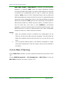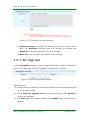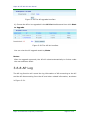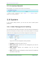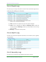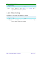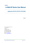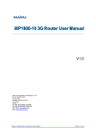
1
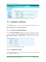
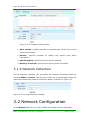
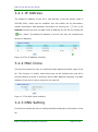
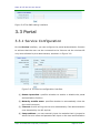
AC MT-W101M User Manual
(Applicable to MT-W101M)
V1.0
Maipu Communication Technology Co., Ltd
No. 16, Jiuxing Avenue
Hi-tech Park
Chengdu, Sichuan Province
People’s Republic of China - 610041
Tel: (86) 28-85148850, 85148041
Fax: (86) 28-85148948, 85148139
URL: http: // www.maipu.com
Email: [email protected]
Maipu Confidential & Proprietary Information
Page 1 of 38
Maipu AC MT-W101M User Manual
Copyright
Copyright ©2013, Maipu Communication Technology Co., Ltd. All Rights Reserved.
No part of this manual may be reproduced or transmitted in any form or by any means
without prior written consent of Maipu Communication Technology Co., Ltd.
and
are trademarks of Maipu Communication Technology Co., Ltd.
All other trademarks that may be mentioned in this manual are the property of their
respective owners.
The information in this document is subject to change without notice. Every effort has
been made in the preparation of this document to ensure accuracy of the contents, but all
statements, information, and recommendations in this document do not constitute the
warranty of any kind, express or implied.
Security Statement
Important! Before powering on and starting the product, please read the security and
compatibility information of the product.
Environmental protection
This product has been designed to comply with the environmental protection requirements.
The storage, use, and disposal of this product must meet the applicable national laws and
regulations.
Maipu Confidential & Proprietary Information
Page 2 of 38
Maipu AC MT-W101M User Manual
Contents
Copyright ....................................................................................................................................... 2
1 Hardware Installation............................................................................................................ 5
1.1 Power Cable Connection ..................................................................................................... 5
1.2 Power on and Start AC ........................................................................................................ 5
2 Detailed Configuration Guide ............................................................................................. 6
2.1PC Configuration .................................................................................................................. 6
3 System Login.......................................................................................................................... 10
3.1 System Status .................................................................................................................... 11
3.1.1 Device Information ................................................................................................. 11
3.1.2 System Load ........................................................................................................... 11
3.1.3 Network Detection ................................................................................................. 12
3.2 Network Configuration ...................................................................................................... 12
3.2.1 IP Address ............................................................................................................... 13
3.2.2 MAC Clone .............................................................................................................. 13
3.2.3 DNS Setting............................................................................................................. 13
3.3 Portal ................................................................................................................................. 14
3.3.1 Service Configuration ............................................................................................. 14
3.3.2 Customized Logo .................................................................................................... 15
3.3.3 Fixed User ............................................................................................................... 16
3.3.4 Mobile User ............................................................................................................ 17
3.3.5 Exception IP Address .............................................................................................. 18
3.3.6 Exception MAC Address ......................................................................................... 18
3.3.7 Authentication List ................................................................................................. 19
3.3.8 Service Log ............................................................................................................. 20
3.4 Roam set............................................................................................................................ 20
3.4.1 Roam Service .......................................................................................................... 20
3.4.2 Roam Log ................................................................................................................ 21
3.5 RADIUS Proxy .................................................................................................................... 21
3.5.1 Server Configuration .............................................................................................. 21
3.5.2 Client Configuration ............................................................................................... 22
3.6 AP Management ................................................................................................................ 22
3.6.1 AP Status ................................................................................................................ 22
3.6.2 User Status ............................................................................................................. 23
3.6.3 User Statistics ......................................................................................................... 24
Maipu Confidential & Proprietary Information
Page 3 of 38
Maipu AC MT-W101M User Manual
3.6.4 Service Configuration ............................................................................................. 24
3.6.5 AP Template ........................................................................................................... 25
3.6.6 MAC Filtering.......................................................................................................... 28
3.6.7 AP Upgrade ............................................................................................................. 29
3.6.8 AP Log ..................................................................................................................... 30
3.7 License Manager ............................................................................................................... 31
3.7.1 Control Authorize ................................................................................................... 31
3.7.2 License Record........................................................................................................ 32
3.8 System ............................................................................................................................... 32
3.8.1 Web Management Setting ..................................................................................... 32
3.8.2 Administrator Setting ............................................................................................. 33
3.8.3 Profiles.................................................................................................................... 33
3.8.4 Firmware Upgrade .................................................................................................. 34
3.8.5 System Time ........................................................................................................... 35
3.8.6 OUI Update ............................................................................................................. 36
3.8.7 AC Restart ............................................................................................................... 36
3.9 System Log......................................................................................................................... 36
3.9.1 Event Log ................................................................................................................ 37
3.9.2 Alarm Log ............................................................................................................... 37
3.9.3 Security Log ............................................................................................................ 37
3.9.4 Network Log ........................................................................................................... 38
Maipu Confidential & Proprietary Information
Page 4 of 38
Maipu AC MT-W101M User Manual
1 Hardware Installation
1.1 Power Cable Connection
Connect the AC power cable in the following steps:
Step 1: Insert one end of the power cable of the AC into the power socket on the
back panel of the AC cabinet and insert the other end of the power cable
into external AC power socket.
Step 2: Check whether the PWR indicator on the front panel of the AC is on. If
yes, in indicates that the power cable is connected correctly.
1.2 Power on and Start AC
Step 1: Insert the AC 220 V power cable and turn on the power switch.
Step 2: Check and ensure that the PWR indicator on the front panel is on.
Step 3: Wait about 10S and the SYS indicator flashes regularly.
Thus, the AC is normally started.
Maipu Confidential & Proprietary Information
Page 5 of 38
Maipu AC MT-W101M User Manual
2 Detailed Configuration
Guide
2.1PC Configuration
To facilitate the user management, the AC integrates the web management
function. Through this function, we can realize various management functions in
a simple mode to facilitate using. When the user configures the hardware, the
user can use the PC to configure the AC.
Through the PC connected to the AC, the user can easily perform the web
management after the following configuration.
The default IP address of the AC is 192.168.180.1 and subnet mask is
255.255.255.0. These parameters can be set as required. The following takes
the default value as an example. The PC is set by the following steps:
1) Connect the PC to the port of the AC.
2) Set the IP address of the PC.
3) Select Network > Network > Local Connection.
4) Right-click Local Connection and click Properties on the displayed
menu.
5) Select Internet Protocol Version 4 (TCP/IPv4), as shown in Figure
2-1.
Maipu Confidential & Proprietary Information
Page 6 of 38
Maipu AC MT-W101M User Manual
Figure 2-1 Select Internet TCP/IP protocol on the attribute window
Click Properties to set the IP address of the PC.
On the Internet Protocol Version 4 (TCP/IPv4) Properties dialog box,
choose Use the following IP address and input 192.168.180.xxx in IP
address, 255.255.255.0 in Subnet mask, and input 192.168.180.1 (default IP
address of the AC) in Default gateway.
Maipu Confidential & Proprietary Information
Page 7 of 38
Maipu AC MT-W101M User Manual
Figure 2-2 Input IP address on the TCP/IPv4 attribute interface
1) Click OK to complete the configuration.
2) Test whether the PC is connected to the AC.
3) Choose Start > Run. Input cmd > and click OK.
4) Execute the ping command in command prompt to test whether the
connection succeeds.
5) Ping 192.168.180.1.
The result is displayed, as shown in Figure 2-3.
Figure 2-3 Connection success between the PC and AC
Maipu Confidential & Proprietary Information
Page 8 of 38
Maipu AC MT-W101M User Manual
If the information in Figure 2-3 is displayed, it indicates that the connection
succeeds.
The result may also be displayed, as shown in Figure 2-4.
Figure 2-4 Connection failure between the PC and AC
If the information in Figure 2-4 is displayed, it indicates that the PC is not
correctly connected to the AC.
In this case, you should check:
1) Check whether the indicator is on.
2) Check whether the TCP/IP is correctly filled.
Maipu Confidential & Proprietary Information
Page 9 of 38
Maipu AC MT-W101M User Manual
3 System Login
The
AC
provides
the
local
and
remote
web
management.
Input
http://192.168.180.1 in the address bar of the Internet browser to log in to the
AC configuration interface. The login interface is displayed, as shown in Figure
3-1.
Figure 3-1 The AC configuration interface
Both the default user name and password of the AC are admin and the default
gateway is 192.168.180.1.
After correctly logging in to the system, the homepage is displayed, as shown in
Figure 3-2. The homepage may vary slightly for different models.
Maipu Confidential & Proprietary Information
Page 10 of 38
Maipu AC MT-W101M User Manual
Figure 3-2 The homepage displayed after logging in to the system
3.1 System Status
On the Status interface, you can view the related system information, such as
Device Information and Network Detection.
3.1.1 Device Information
On the Device Information interface, the device information of the AC,
including Hostname, Device Model, Device Number, Firmware Version,
MAC Address, Uptime, and System time, is displayed as shown in Figure
3-3.
Figure 3-3 The device information interface
3.1.2 System Load
On the System Load interface, you can view the current AC memory and CPU
load, as shown in Figure 3-4.
Maipu Confidential & Proprietary Information
Page 11 of 38
Maipu AC MT-W101M User Manual
Figure 3-4 The system load interface
(1) Auto refresh: specifies whether to automatically refresh the current
system load status.
(2) Service:
specifies
whether
to
enable the
system
load
alarm
mechanism.
(3) CPU Threshold: specifies the CPU alarm threshold.
(4) Memory Threshold: specifies the memory alarm threshold.
3.1.3 Network Detection
On the detection interface, you can detect the network connection status by
choosing PING or Tracert. The user can choose the corresponding function as
required to detect the network connection status, as shown in Figure 3-5.
Figure 3-5 The ping detection interface
3.2 Network Configuration
In the Network function, you can modify the related network parameter.
Maipu Confidential & Proprietary Information
Page 12 of 38
Maipu AC MT-W101M User Manual
3.2.1 IP Address
The default IP address of the AC is 192.168.180.1 and the subnet mask is
255.255.255.0, which can be modified. You can modify the IP information,
subnet information, and gateway information by clicking the
icon in the
Operate column and you can add a new IP address for the AC by clicking the
icon. (Note: The default IP address of the AC can only be modified and
cannot be deleted.)
Figure 3-6 The IP address interface
3.2.2 MAC Clone
This function allows the user to modify the MAC address and MTU value of the
AC. This function is usually used before the old AP replaces the new AP to
prevent causing a series of problems due to MAC address changing. The MAC
address of the old AC can be copied to the new AC.
Figure 3-7 The MAC clone interface
3.2.3 DNS Setting
This function allows the user to modify the DNS configuration information of the
AC.
Maipu Confidential & Proprietary Information
Page 13 of 38
Maipu AC MT-W101M User Manual
Figure 3-8 The DNS setting interface
3.3 Portal
3.3.1 Service Configuration
On the Service interface, you can configure the portal authentication function
to achieve that the user can be connected to the Internet via the wireless AP
only when allowed by the administrator, as shown in Figure 3-9.
Figure 3-9 The service configuration interface
(1) Status Operation: specifies whether to enable or disable the portal
authentication function.
(2) Maturity mobile users: specifies whether to automatically clear the
due mobile account.
(3) Timeout: the AC will log out the user automatically if the authentication
user detected by the AC expires.
(4) Jump address: you can manually input the website that is jumped to
when the user name and password are input on the user authentication
Maipu Confidential & Proprietary Information
Page 14 of 38
Maipu AC MT-W101M User Manual
interface. If this option is null, it will automatically jumped to the
previously opened interface.
(5) Authentication error: specifies the error prompt message that is
returned to the user when the account is invalid and the password is
wrong.
(6) Default Username: the default username shown on the user
authentication interface.
(7) Default Password: the default password shown on the user
authentication page (hidden).
(8) Service log: specifies whether the service log of the portal
authentication function is enabled or disabled.
(9) Save: specifies the static configuration written in the AC to enable the
parameter to take effect.
3.3.2 Customized Logo
On the Custom Logo interface, you can upload the logo pushed to the user
authentication interface and input the related information displayed on the
authentication interface, as shown in Figure 3-10.
Figure 3-10 The self-defined logo interface
(1) LOGO Image: specifies the logo to be uploaded. (logo on the upper left
corner of the push page)
(2) Publicity image: specifies the background image to be uploaded.
(publicity image on the left side on the push page)
Maipu Confidential & Proprietary Information
Page 15 of 38
Maipu AC MT-W101M User Manual
(3) Custom BackgroundColor: set the background color displayed on the
authentication interface.
(4) Custom Information: input the related information displayed on the
authentication interface. (characters displayed on the right side of the
push page).
Notes: Different logos can be uploaded based on different SSIDs.
3.3.3 Fixed User
On the Add interface, you can configure the fixed user account and password
for logging into the wireless authentication system, as shown in Figure 3-11.
Figure 3-11 The adding fixed user interface
(1) State operation: specifies whether to enable or disable the currently
configured fixed user.
(2) Username: specifies the user name for logging in to the portal
authentication.
(3) Password: specifies the password for logging in to the portal
authentication.
(4) Modify password: specifies whether to allow the user to modify the
password of the current authentication account.
Maipu Confidential & Proprietary Information
Page 16 of 38
Maipu AC MT-W101M User Manual
(5) Account sharing: specifies whether to enable or disable the function of
allowing multiple users to use the same account.
(6) Bind IP: specifies the IP address of the client that this fixed account
wants to be bound to. After the binding, other clients cannot use this
account.
(7) Bind MAC: specifies the MAC address of the client that this fixed
account wants to be bound to. After the binding, other clients cannot
use this account.
(8) Account expired: specifies whether to enable of disable if the current
account will expire.
(9) Remarks: notes for this user account.
3.3.4 Mobile User
On the Mobile Users interface, you can use the AC to automatically generate
the mobile account for logging in to the portal authentication, which will
facilitate you to manage the inner mobile users, as shown in Figure 3-12.
Figure 3-12 The mobile user interface
(1) Auto: click Auto to choose the number of the mobile accounts that can
be generated and the expiration time.
(2) Delete: can automatically delete the due account.
(3) Username: specifies the user name of the mobile account generated.
Maipu Confidential & Proprietary Information
Page 17 of 38
Maipu AC MT-W101M User Manual
(4) Password: specifies the password of the mobile account generated.
(5) Source: specifies whether the mobile account is generated by the AC.
(6) Expire time: specifies the expiration time of the mobile account.
(7) Operate: you can print or copy the mobile account.
3.3.5 Exception IP Address
On the Add interface, you can set the exception IP address that is not restricted
by the portal authentication function, as shown in Figure 3-13.
Figure 3-13 The adding exception IP address interface
(1) State operation: specifies whether to enable or disable the current
exception IP address rule.
(2) Start IP: specifies the start IP address of the exception IP address.
(3) End IP: specifies the end IP address of the exception IP address.
(4) Remarks: specifies the remarks of the exception IP address rule.
3.3.6 Exception MAC Address
On the Add interface, you can set the exception MAC address that is not
restricted by the portal authentication function, as shown in Figure 3-14.
Maipu Confidential & Proprietary Information
Page 18 of 38
Maipu AC MT-W101M User Manual
Figure 3-14 The adding exception MAC address interface
(1) Status operation: specifies whether to enable or disable the current
exception MAC rule.
(2) MAC Address: specifies the exception MAC address to be filled.
(3) Remarks: specifies the remarks for the exception IP address rule.
3.3.7 Authentication List
On the Auth List interface, you can view the detailed information of the host in
authentication, as shown in Figure 3-15.
Figure 3-15 The authentication list interface
(1) SN: specifies the SN of the user-authenticated AP.
(2) Username: specifies the portal authentication account for user
authentication.
(3) IP Address: specifies the IP address information of the authentication
user.
(4) MAC Address: specifies the MAC address information of the
authentication user.
(5) Logintime: specifies the last authentication time.
(6) Activetime: specifies the last time that the AC detects the
authentication user.
Maipu Confidential & Proprietary Information
Page 19 of 38
Maipu AC MT-W101M User Manual
(7) Operation: specifies that the authentication user can be logged out
manually.
3.3.8 Service Log
On the Service log interface, you can view the related logs of the portal
authentication, as shown in Figure 3-16.
Figure 3-16 The service log interface
(1) Time: specifies the time that the log content is generated.
(2) Level: specifies the importance degree of the log content.
(3) Message: specifies the detailed content description of the log.
(4) Export: exports the authentication service log to facilitate querying.
3.4 Roam set
3.4.1 Roam Service
On Roam Service Page, you can adjust the Roam sensitivity by choosing
High/Of/Low, or you can choose not roam to disable roam function, Shown as
Figure 3-17
Maipu Confidential & Proprietary Information
Page 20 of 38
Maipu AC MT-W101M User Manual
Figure 3-17 Roam Service
3.4.2 Roam Log
Roam Log records the history of the roamed devices, shown as Figure 3-18.
Figure 3-18 Roam log
3.5 RADIUS Proxy
3.5.1 Server Configuration
Figure 3-19 RADIUS Proxy-Server Configuration
(1) Certificate upload: upload the certificate file here.
(2) Private Key upload: upload the private key here.
(3) Private Key password: set the private key.
(4) NAS-Identifier: the proxy device’s identifier to Radius Server; here it is the
AC’s identifier.
Maipu Confidential & Proprietary Information
Page 21 of 38
Maipu AC MT-W101M User Manual
(5) NAS-IP-Address: the proxy device’s IP address to Radius Server; here it is
the AC’s IP address.
(6) Called-Station-ID: the proxy device’s MAC address to Radius Server; here
it is the AC’s MAC address.
(7) Service port: the port that Radius service is used.
(8) Server IP: Radius Server’s IP address.
(9) Server password: the password here should match the one set on the
Radius Server.
3.5.2 Client Configuration
Figure 3-20 RADIUS Proxy-Client Configuration
3.6 AP Management
3.6.1 AP Status
In the AP status function, you can view the status information of all the APs that
are registered on the AC in the current status, including the host name,
firmware version, IP address, and SSID of each AP. You can modify the related
information of an AP through the operation function, as shown in Figure 3-21.
Figure 3-21 The AP status interface
Click the edit function option and the Edit interface is displayed, as shown in
Figure 3-22.
Maipu Confidential & Proprietary Information
Page 22 of 38
Maipu AC MT-W101M User Manual
Figure 3-22 The edit interface
Through the edit function, you can set the private parameter for the specified AP
and modify the work channel of the AP and host name. The host name can be
used to identify the AP and it is recommended that the host name be used as a
remarks function. Meanwhile, you can adjust the AP public parameter by
modifying the AP template. For details, refer to the AP template function option.
Delete: you can delete the offline AP from the AP list by clicking Delete. When
the specified AP is online, this function is unavailable.
Restart: you can reboot the selected AP by clicking Restart.
3.6.2 User Status
On the WLAN Clients interface, you can view the status information of the
wireless users connected to the AP.
Figure 3-23 The user status interface
(1) AP: specifies the host name of the current AP.
(2) MAC Address: specifies the MAC address of the host that is connected
successfully.
(3) Tx: specifies the traffic volume that is sent by the host.
(4) Rx: specifies the traffic volume that is received by the host. specifies
the number of data packages that is sent by the host.
Maipu Confidential & Proprietary Information
Page 23 of 38
Maipu AC MT-W101M User Manual
(5) Tx Rate: specifies the current rate of the data package sent by the
host.
(6) RSSI: specifies the signal strength between the host and AP.
(7) Link Time: specifies the time that the host is connected to the AP.
3.6.3 User Statistics
on the Statistics interface, you can view the peak number of active APs and
active hosts, which can be displayed in different time. The traffic graph is
displayed, as shown in Figure 3-24.
Figure 3-24 The user statistics interface
3.6.4 Service Configuration
On the Service interface, you can set whether to allow the current AC to
Maipu Confidential & Proprietary Information
Page 24 of 38
Maipu AC MT-W101M User Manual
manage the AP, as shown in Figure 3-25.
Figure 3-25 The service configuration interface
(1) Control: specifies whether to enable or disable the function of
managing the AP.
(2) New Device registration: specifies whether to allow or refuse the
new AP to register to the AC.
(3) Start IP Address: specifies the start IP address that the AC allocates
to the AP.
(4) Count: specifies the total number of IP address pools that the AC
allocates to the AP.
(5) Gateway: specifies the default gateway that the AC allocates to the AP.
(6) DNS: specifies the DNS address that AC allocates to the AP.
3.6.5 AP Template
On the Edit interface, you can set the public information of the APs under the
charge of AC. Where, the T1 template is the built-in template in the system,
which can only be modified and cannot be deleted.
The default template is the T1 template. The user can specify the default
template for the new AP by modifying the default template.
Maipu Confidential & Proprietary Information
Page 25 of 38
Maipu AC MT-W101M User Manual
Figure 3-26 The adding template interface
(1) Name: specifies the name of the current template.
(2) Admin Password: specifies the administrative password for logging
in to the AP using the current template. For example, when the
administrative password of the T1 template is 1, then the user name is
admin and the password is 1 for logging in to the AP using the T1
template.
(3) VLAN ID: specifies the data package that is reached to the AP or the
data package that is sent by the AP. For example, visiting the AP web
page, pinging AP, and communication between the AP and AC.
(4) LAN VLAN ID: specifies the VLAN ID that is carried when the device
connecting to the LAN port sends data.
(5) WLAN: allows the user to specify whether to enable the wireless
network function of the current template by the user. When the
Enabled option is deselected, the WLAN of the current template will
be disabled to achieve environmental wireless network.
(6) Band: allows the WLAN client to be connected to the wireless router in
the B, G, or N mode. 11B indicates 11 Mbps, 11G indicates 54 Mbps,
and 11N indicates 300 Mbps. Different wireless modes are selected to
adapt to different scenarios.
(7) RF Power: allows the user to adjust the wireless power, 100% by
default.
Maipu Confidential & Proprietary Information
Page 26 of 38
Maipu AC MT-W101M User Manual
(8) Channel: also called the wireless channel, is the data signal
transmission channel through the wireless signal medium.
(9) User Isolation: specifies the visit control function based on the MAC
address. When this function is enabled, the wireless clients connected
to the router cannot visit each other.
(10)
DHCP PATCH:The DHCP patch function is to solve the problem that
some Operating System cannot accept broadcast DHCP packets so as
not to obtain IP address.
(11)
DHCP Band: when enabled, DHCP packet will only send to the
specified DHCP Sever IP.
Note: AP would use unicast instead of broadcast packet when it’s
enabled. Make sure the DHCP server would accept the DHCP unicast
packet.
(12)
Portal Auth Type: allows users to choose different auth type from
3 available options: Local, Cloud, or disable. When Local is chosen,
Portal Service Address should be set later; when Cloud is chosen,
Portal Service URL should be set later.
(13)
Portal Network Outage: it specifies how AP would work when AP
fails to communicate with AC. When set as OPEN, AP will allow clients’
data to pass; when set as BLOCK, AP will NOT allow clients’ data to
pass.
(14)
Portal Auth: allows users to specify which SSID(s) will enable the
portal service.
(15)
SSID: short for Service Set Identifier can divide a WLAN into
several sub-networks requiring different authentications. Each
sub-network needs independent authentication and only users
passing
the
authentication
can
enter
the
corresponding
sub-network. This can prevent the unauthorized users entering
this network. That is to say, SSID is the name of your network.
(16)
Broadcast SSID: when this function is not set to Enabled, the AP
will stop to broadcast its own SSID. If the user wants to connect to the
wireless network, the SSID must be filled manually.
(17)
VLAN ID: specifies the VLAN ID of the user using this SSID.
(18)
Encryption: specifies the encryption mode for the wireless
network. If no encryption mode is selected, the authentication
password is not required when connecting to the wireless network. If
Maipu Confidential & Proprietary Information
Page 27 of 38
Maipu AC MT-W101M User Manual
WEP, WPA, WPA2 or WPA/WPA2 is selected, the authentication
password is required. WEP, short for Wired Equivalent Privacy,
encrypts the data transmitted in wireless mode between two devices
to prevent the unauthorized user to bug or invade the wireless
network. WPA, short for Wi-Fi Protected Access, has the WPA and
WPA2 standards and protects the Wi-Fi security. It is generated based
on several serious weaknesses found in the last generation of system
WEP by the researcher. PSK, short for pre-shared key, also called the
WPA personal edition or WPA2 personal edition to enable users to
use the same key. This mode is risky. RADIUS, a port-based
standard, is used to authenticate the wireless network access. The
RADIUS protocol is used for authentication and is also called WPA
enterprise edition or WPA2 enterprise edition.
Notes:
(1)
After the template content is modified, the configuration will be
effect for all the online APs using this template. The offline APs will
apply the modified content when the APs log in to the AC the next
time.
(2)
You can specify different APs to use different templates to modify
some public parameters of the AP in batch, which can be modified in
AP status.
3.6.6 MAC Filtering
On the MAC Filter interface, you can configure the MAC filtering function of the
AC.
Choose WEB Management > AP Management > MAC Filter to enter the
MAC Filter interface, as shown in Figure 3-27.
Maipu Confidential & Proprietary Information
Page 28 of 38
Maipu AC MT-W101M User Manual
Figure 3-27 The MAC filtering interface
(1) Status operation: specifies the filtering rule for the content in the
MAC list. Blacklist indicates that the content is blocked and
Whitelist indicates that the content is allowed.
(2) MAC List: fills the MAC information to be filtered.
3.6.7 AP Upgrade
On the AP Update interface, you can upgrade the APs in batch, as shown in
Figure 3-28. Note that the AP is upgraded, instead of the AC itself.
Figure 3-28 The AP upgrade interface
Upgrade steps:
1) Prepare the new firmware of the AP and choose the new firmware of the AP
by the browsing mode.
2) Click I know the upgrade risk and view the warning. Click Upload to
confirm the upgrade.
3) Click Next after the upload succeeds. Click Delete if the file needs to be
deleted.
Maipu Confidential & Proprietary Information
Page 29 of 38
Maipu AC MT-W101M User Manual
Figure 3-29 The AP upgrade interface
4) Choose the AP to be upgraded in the AP List interface and then click Start
to Upgrade.
Figure 3-30 The AP list interface
You can view the AP upgrade statis by State.
Notes:
After the upgrade succeeds, the AP will reboot automatically to further make
the new software effect.
3.6.8 AP Log
The AP Log function will record the log information of AP connecting to the AC
and the AP disconnecting from the AC and other related information, as shown
in Figure 3-31.
Maipu Confidential & Proprietary Information
Page 30 of 38
Maipu AC MT-W101M User Manual
Figure 3-31 The AP log interface
3.7 License Manager
3.7.1 Control Authorize
On Control Authorize page, you can check the AP license & Switch License,
and update the license file, show as Figure 3-32.
Figure 3-32 License Manager-Control Authorize
(1) Serial Number: displays the current AC’s Serial Number.
(2) AP License: the maximum number of APs that AC could support.
(3) Switch License: the maximum number of supported switch that
AC could work with.
(4) License file: upload a new license file to increase/decrease the
number of AP & Switch that AC could Support.
Maipu Confidential & Proprietary Information
Page 31 of 38
Maipu AC MT-W101M User Manual
3.7.2 License Record
On this page, you could see the license record history.
Figure 3-33 License Record
3.8 System
In the system setting function, you can set the device related system
parameters.
3.8.1 Web Management Setting
You can modify the host name of the device. The host name will be displayed in
the device information, the device number of the host by default. You can also
modify the web management port and Web management expiration time.
Figure 3-34 The web management setting interface
(1) Hostname: specifies the name of the AC.
(2) WEB service port: specifies the web management port used for
logging in to the AC.
(3) WEB
timeout:
specifies
the
expiration
time
for
the
web
communication.
(4) Save: specifies the static configuration written into the AC to enable the
parameter to take effect.
Maipu Confidential & Proprietary Information
Page 32 of 38
Maipu AC MT-W101M User Manual
3.8.2 Administrator Setting
You can modify the default administrator admin and password of the device, add
the administrator, and set the authority of the new administrator.
Figure 3-35 The adding administrator interface
(1) User name: specifies the user name for logging in to the system.
(2) Password: specifies the password for the user.
(3) Confirm password: confirms the password again, which must be
identical to the previously input password.
(4) Authority: specifies the operations that the user has the right to
operate in the system.
3.8.3 Profiles
Restore Factory
You can clear the current configuration and restore the device to the factory
setting status on the Restore factory interface.
Figure 3-36 The restore factory interface
Maipu Confidential & Proprietary Information
Page 33 of 38
Maipu AC MT-W101M User Manual
Restore backup
You can import the previously saved configuration to the device on the Restore
backup interface.
Figure 3-37 The restore backup interface
Save Current Configuration
You can save all the configurations of the current device to a configuration file on
the Save current interface. When the device is restore to the factory setting,
you can use the backup restoration function to import the previous configuration
to the device.
Figure 3-38 The save current configuration interface
3.8.4 Firmware Upgrade
Firmware upgrade is a necessary function for the network product. The software
must be optimized and upgraded continuously to satisfy the changeable
network environment and meet different requirements. Whether the software
upgrade can be promoted to meet the changeable requirements is more and
more concerned by users. This function is used to upgrade the AC, as shown in
Figure 3-39.
Maipu Confidential & Proprietary Information
Page 34 of 38
Maipu AC MT-W101M User Manual
Figure 3-39 The firmware upgrade interface
Current version: displays the software version number used by the current
system.
Upgrade file: specifies the software package for upgrading the system, which
is provided by the manufacturer.
Notes:
(1) All the options with asterisk (*) are mandatory.
(2) There is risk for firmware upgrading. Do not pause during the upgrading.
The whole upgrading process will take about three to five minutes. A
message will be prompted when the upgrade succeeds, therefore please
wait patiently during the upgrading.
(3) After the upgrade succeeds, the system will reboot automatically to
take the new version into effect. If the upgrade error message is
prompted, do not reboot the AC and just repeat the upgrade operations
until the upgrade succeeds. If the upgrade error occurs and the AP is
powered off or the AC is powered off during upgrading, the system will
fail to be started. In this case, contact the technical personnel for
support.
3.8.5 System Time
On the System time interface, you can set the time for the AC, as shown in
Figure 3-40.
Figure 3-40 The system time interface
(1) Update method: specifies the mode for modifying the time. It can be
set to Synchronization time and Manual Setup.
(2) Computer time: specifies the time synchronous with the PC.
Maipu Confidential & Proprietary Information
Page 35 of 38
Maipu AC MT-W101M User Manual
(3) System time: specifies the time displayed on the router time setting
interface.
(4) System timezone: specifies the time zone in which the user locates.
(5) Network time: the router will be automatically synchronized the time
with the time server in a regular period.
(6) Time Service: the user can choose whether to enable the time
synchronization function.
3.8.6 OUI Update
You can update the OUI info by enabling OUI update on this page. The update
frequency could also be configured here.
Figure 3-41 System-OUI Update
3.8.7 AC Restart
On the Restart interface, you can reboot the AC, as shown in Figure 3-42.
Figure 3-42 The AC restart interface
3.9 System Log
The AC running status is recorded and saved as a log to help us locate the fault,
troubleshoot, and manage network security, and help us to analyze whether the
AC is normal and whether the network is healthy.
Maipu Confidential & Proprietary Information
Page 36 of 38
Maipu AC MT-W101M User Manual
3.9.1 Event Log
The event log is the login information on the AC and records the logs such as
configuring and modifying the information.
Figure 3-43 The event log interface
(1) Time: specifies the instant time when the system changes.
(2) Level: can be classified into Info and Warning. Info records the
running events and Warning reminds you notice based on the running
event recorded.
(3) Message: records the running event.
3.9.2 Alarm Log
The alarm log records the important operations, such as factory reset, upgrade,
and accidents.
Figure 3-44 The alarm log interface
3.9.3 Security Log
The security log records the logs related to the system security.
Maipu Confidential & Proprietary Information
Page 37 of 38
Maipu AC MT-W101M User Manual
Figure 3-45 The security log interface
3.9.4 Network Log
The network log records the logs related to the network.
Figure 3-46 The network log interface
Maipu Confidential & Proprietary Information
Page 38 of 38