1
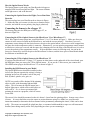
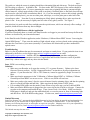
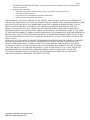
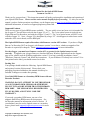
Instruction Manual for the Optical RPM Sensor
Document Version 2.2
Thank you for your purchase! This instruction manual will guide you through the installation and operation of
your Optical RPM Sensor. Please read the entire manual carefully before proceeding. If, after you read the
manual, you have further questions or problems, see the Support page on http://www.eagletreesystems.com for
additional information, or email us at [email protected].
Supported Products
There are two types of Optical RPM sensors available. The one with 4 wires (one loose wire) is intended for
the eLogger V1, but will also work with the eLogger V2 or V3. The 3 wire optical sensor is used with our
Flight, Boat and Car Recorders, and with the eLogger V2 and V3. The 3 wire optical sensor will NOT work
with the eLogger V1. Note: eLogger V2 is designated by a large “V2” which appears in white letters on the
underside of the circuit board, near the RPM pins.
The Optical RPM Sensor requires Recorders with firmware version 4.XX or later. If you have a Flight,
Boat or Car Recorder (NOT an eLogger) with firmware version 3.xx or lower, a hardware upgrade of the
Recorder is required (fee charged). Email [email protected] for more information.
For the eLogger, you must have firmware version 4.33 or greater for the Optical sensor to work
correctly. To upgrade your eLogger firmware, download the latest Windows application from the Support
page of our website (must be Windows application version 3.29 or later), and after installation, choose
“Hardware, Firmware Control” and follow the instructions. If your Windows CD already has version 3.29 or
later printed on the label, you should not need to do this.
Packing List
Your package should include the following: Optical RPM Sensor,
and a printed version of this manual. Please check your
packaging for printed addenda to this manual which may be
included if changes were made after printing.
Use of this RPM Sensor as a Secondary RPM Sensor with our
Recorder Products
WARNING: DO NOT ATTEMPT TO USE THIS SENSOR
AS A SECONDARY RPM SENSOR, OR OTHERWISE
PLUG IT INTO A PORT OTHER THAN THE PRIMARY
RPM PORT. THE SENSOR WILL BE DESTROYED
IF YOU DO THIS, AND IT WILL VOID THE
WARRANTY.
If you need a secondary RPM sensor, use one of our
magnetic Hall Effects RPM sensors for this purpose. See
the Recorder manual for information on how to do this. If
you absolutely need to use the Optical sensor as a secondary
sensor, please email [email protected] for more
info.
Copyright © 2006 Eagle Tree Systems, LLC
http://www.eagletreesystems.com
Page 2
How the Optical Sensor Works
The Optical Sensor works with your Data Recorder/eLogger to
measure RPM via reflected infrared light. The sensor contains
an IR light source, and an IR detector.
Connecting the Optical Sensor the Flight, Car or Boat Data
Recorder
The sensor plugs into your Data Recorder as shown in Figure
1. Make sure that you connect it in the correct location on the
recorder, and with the correct polarity (the plug is polarized).
Connecting the Sensor to the eLogger V3
The Sensor plugs into the RPM port of the eLogger V3, as
shown in Figure 2A.
Connecting the 4 Wire Optical Sensor to the MicroPower V1 or MicroPower V2
The 4 Wire Optical sensor plugs into your MicroPower V1 or V2 as shown in Figure 2. Make sure that you
connect it in the correct location on the MicroPower, and with the correct polarity! Note that if you use a
temperature sensor along with the Optical sensor, the pin on the optical sensor’s loose wire can be snapped into
the spare slot in the temperature sensor’s connector. Alternatively, you can spin the temperature sensor around
so that the two wires are reversed, and the spare slot is hanging out over the edge of the MicroPower (it is ok to
reverse the polarity of the temperature sensor). If the temperature sensor is not being used, the pin on the
loose wire connects by itself to the pin on the MicroPower as shown, and the loose piece of heat-shrink should
be slid down to insulate the pin.
Connecting the 3 Wire Optical Sensor to the MicroPower V2
If you have the MicroPower V2 (large “V2” appears in white letters on the underside of the circuit board, near
the RPM pins) then you can use the 3 Wire Optical sensor. If you use the 3 Wire sensor, just connect the 3
Wire RPM sensor plug to the MicroPower V2, as shown in figure 2.
Installing the RPM Sensor in your Model
The Optical RPM sensor should be installed so that
its face (the flat part opposite the wiring) is facing a
spinning surface on your model, such as the prop
hub, flywheel, spinner, axle, gear, etc.
NOTE: best results will be obtained if the spinning
object is solid, with alternating light and dark
colors. This is because the Optical sensor has a
built in light source, which needs a solid object to
reflect off of. So, we do not recommend just
pointing the sensor at a propeller, which of course
is not solid.
The sensor’s face should be mounted so that it is about 1-4 mm from the spinning object. In most cases, closer
is better. It is not a bad idea to test the sensor at various distances using Live Mode (see your Recorder
instruction manual) to determine the best distance before permanently mounting the sensor, if this can be done
safely. The sensor can normally be glued into place, or mounted with heatshrink or tape to a self-constructed
bracket (brass tubing usually works well), depending on where you are mounting it.
Copyright © 2006 Eagle Tree Systems, LLC
http://www.eagletreesystems.com
Page 3
The surface to which the sensor is pointing should have alternating light and dark areas. The dark area must
NOT be shiny or reflective. It should be flat. For best results, half (180 degrees) of the surface should be
light, and half should be dark. If you are mounting the sensor near a spinning hub that is constructed light
colored material , a black magic marker (if the result is not shiny), flat black paint, or flat black electrical tape
can be used to color half of the circumference black. Or, if you are mounting it next to dark colored spinning
object (such as black plastic), you can use white paint, white tape, or a white paint pen to make half of the
circumference white. Note that if you are mounting on a black plastic spinning object, make sure that the
plastic is flat. It may be necessary to lightly sand it to take off any glossy surface. See Figure 3.
Note also that it is good to avoid direct sunlight onto the optical sensor, which can adversely affect readings. If
possible, shield the sensor from any direct sunlight.
Configuring the RPM Sensor with the Application
If you have not already done so, install your Data Recorder or eLogger in your model and set up the Recorder
software as described in your instruction manual.
In the Data Recorder Windows application, under “Hardware, Calibrate Motor RPM” choose “I am using the
Optical RPM Sensor.” Then, enter the number of light-colored stripes you have placed on the spinning surface,
and enter the Gear Ratio of your motor (normally 1.0) and choose the location that you have mounted the
optical sensor.
Troubleshooting
Below is a list of problems that may be encountered, and steps to remedy them. If your particular issue is not
addressed by the below, see the Support page on http://eagletreesystems.com or email
[email protected]. Include a full description of your problem, your machine configuration,
brands/models of receivers, transmitters and servos, application and Recorder firmware version if possible
(from Help->About in the app) and any other relevant details.
Issue: RPM is not working correctly
Solutions:
• Make sure your Recorder or eLogger has version 4.33 or greater firmware. Update to the latest
firmware from our website. See the “Supported Products” section above for more information on
updates – if your Recorder has 3.XX or 2.XX firmware, it must be upgraded by Eagle Tree on a fee
basis.
• Make sure that the parameters in the "Calibration->Calibrate Motor RPM" or “Calibrate, Calibrate
Ground Speed from RPM” are not set to zero. If this is zero, RPM will read zero.
• Make sure you have the sensor’s face the correct distance from the spinning object, and that the spinning
object is colored half light and half dark. Make sure that the dark portion is NOT glossy.
• For recording RPM, make sure that under Choose What to Log in the app, you have checked RPM.
• Make sure that the RPM sensor is plugged into the correct slot on the recorder or eLogger. Connect the
recorder to the computer and launch the app. Then, choose Tools->Live Mode. Make sure that the
RPM gauge is displayed, and spin the marked hub/axle, or wave the sensor in front of alternating light
and dark areas. See if the RPM reading jumps. If it does not, email [email protected].
Limited Warranty
Eagle Tree Systems, LLC, warrants the Optical RPM Sensor to be free from defects in materials and workmanship for a
period of one (1) year from the date of original purchase. This warranty is nontransferable. If your unit requires
warranty service during this period, we will replace or repair it at our option. Shipping cost to us is your responsibility.
To obtain warranty service, email [email protected] for further instructions.
This limited warranty does not cover:
Copyright © 2006 Eagle Tree Systems, LLC
http://www.eagletreesystems.com
Page 4
•
•
The Software included with the Product. See the Software license agreement for more information on
Software restrictions.
Problems that result from:
o External causes such as accident, abuse, misuse, or problems with electrical power
o Servicing not authorized by us
o Usage that is not in accordance with product instructions
o Failure to follow the product instructions
THIS WARRANTY GIVES YOU SPECIFIC LEGAL RIGHTS, AND YOU MAY ALSO HAVE OTHER RIGHTS
WHICH VARY FROM STATE TO STATE (OR JURISDICTION TO JURISDICTION). OUR RESPONSIBILITY FOR
MALFUNCITONS AND DEFECTS IN HARDWARE IS LIMITED TO REPAIR AND REPLACEMENT AS SET
FORTH IN THIS WARRANTY STATEMENT. ALL EXPRESS AND IMPLIED WARRANTIES FOR THE
PRODUCT, INCLUDING, BUT NOT LIMITED TO, ANY IMPLIED WARRANTIES AND CONDITIONS OF
MERCHANTABILITY AND FITNESS FOR A PARTICULAR PURPOSE, ARE LIMITED IN TIME TO THE TERM
OF THE LIMITED WARRANTY PERIOD AS DESCRIBED ABOVE. NO WARRANTIES, WHETHER EXPRESS OR
IMPLIED, WILL APPLY AFTER THE LIMITED WARRANTY PERIOD HAS EXPIRED. SOME STATES DO NOT
ALLOW LIMITATIONS ON HOW LONG AN IMPLIED WARRANTY LASTS, SO THIS LIMITATION MAY NOT
APPLY TO YOU.
WE DO NOT ACCEPT LIABILITY BEYOND THE REMEDIES PROVIDED FOR IN THIS LIMITED WARRANTY
OR FOR CONSEQUENTIAL OR INCIDENTAL DAMAGES, INCLUDING, WITHOUT LIMITATION, ANY
LIABILTY FOR THIRD-PARTY CLAIMS AGAINST YOU FOR DAMAGES, FOR PRODUCTS NOT BEING
AVAILABLE FOR USE, OR FOR LOST DATA OR LOST SOFTWARE. OUR LIABILITY WILL BE NO MORE
THAN THE AMOUNT YOU PAID FOR THE PRODUCT THAT IS THE SUBJECT OF A CLAIM. THIS IS THE
MAXIMUM AMOUNT FOR WHICH WE ARE RESPONSIBLE. SOME STATES DO NOT ALLOW THE
EXCLUSION OR LIMITATION OF INCIDENTAL OR CONSEQUENTIAL DAMAGES, SO THE ABOVE
LIMITATION OR EXCLUSION MAY NOT APPLY TO YOU.
Copyright © 2006 Eagle Tree Systems, LLC
http://www.eagletreesystems.com