1
3.
USER SELECTABLE STRAPS
The FDD Is eqUipped with the following selectable straps on the main peBA Insertion of a short
bar onto the post pin Is defined as the on·state of the strap
HOO
u
//-SIQn"l
I
nte .... ("ce connecto....
"n
uu
HOL
r
HOH
ERGO MD-21 MICRO FLOPPY DISK DRIVE USER MANUAL REV 2.1 L
-o"k_-,
r
L
~,v
01
r c
DO
~~..J
Figure 3
'i
---I,
~:' ~.. r.
.1
...
II
(wppe c
~m
LJ>..
COb
~
llfl
o
DO and 01 Straps
(b)
3.2
HDH, HOL, Dl ancl HOC Straps
(a) Table 3 shows the combinatIOn of the straps
'e
r
Four deSignating methods are offered for
selection
(1) Selection No 1
The FOO switches the density mode according to the HD IN input signal from the host
HIGH level corresponds to high density mode.
HO IN input Signal from the host
controller
(3) Selection No.3
The FDD switches the density mode automatically by detecting the eXistence of the HD
hole 01 the Inserted diskette
(4) SelectIOn N04
The host controller sWitches
to the HD OUT output signal
from theFDD
",I
I~"=--=y
I
I,
3.1
Ob
Selection
No, 2
DenSity mode designation Host Side
Key·in or software
ON ON
HD IN
(LOW HD)
KeY·1n or software
OPEN
Key·in or software
I
FOO
HD IN v.",
host Side
from
HD IN _."
host Side
from
I AutomatiC by HD
hole sensor
ON I ON
I
~G~U~D)
I ~~mO~~Dslgnal
Automatic by HD
hole sensor
Note
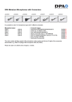
Figure 2 Singal interface connector external view
mark indicates off-state of the strap
Never set any strap combmatlons other than the above
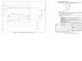
Tabte 3 Function selection for Interface pin No 2
Copyright 1991 by Ergo System International Company Ltd,
2.
(1) Signal interface connector
1. Power Interface Connector and Cable
(1) Power interface connector
I; {~~;
I~~
(a) pin numbers :
4 pins (b) Connector external view:
(c) Power interface connections
Signal Interlace Connector and Cable
--
c~·
See Fig. 1.
See Table 1.
R",,,,r
(a) Pin numbers and pin pitch
254 mm (0.1 in) pitch, 34 pins block header (17 pins double
rows, even number pins are upper side of the FDDl
(b) Connector external view See Fig.2
(c) Interface connection See Table 2
C,'
~
PCB
v I e"
(2) Signal intertace cable
Maximum cable length 1m (3.3 feet), at 1 KG terminator (For daisy chain connection, the
cable length should be less than 1m)
(2) Power interface cable
I
I
Power voltage
DC +5V I
--D I,
I
Any appropriate cables capable of taking the
maximum power consumption of the FDD will
be acceptable.
(OV)
(No connection) w
w
w
w
w
w
Pin numbers
I
1
2
3
4
111,I] 1mI II
I
ll.~ ,~ I~
II
Singals
HD IN/OPEN/HD OUT
I
Directions
IN/OUT
OPEN
RESERVED
INPUT
INDEX
OUTPUT
DRIVE SELECT 0
INPUT
DRIVE SELECT 1
INPUT
RESERVED
INPUT
15
W
16
MOTOR ON
INPUT
W
W
18
DIRECTION SELECT
INPUT
W
STEP INPUT
W
WRITE DATA
INPUT
D
W
WRITE GATE
INPUT
•
W
26
TRACK 00
OUTPUT
W
28
WRITE PROTECT
OUTPUT
W
READ DATA
OUTPUT
W
SIDE ONE SELECT
INPUT
DISK CHANGE
OUTPUT
Figure 1 Power interface connector external view
I
W
-----
~
~\
Pins nos
II
"
•
I
Note
Table 1 DC Power Connector pin-assignment Ei~1
Il~"II' 1
OV
Pin Nos.
'I
W
34
Refer to Item 11 2 as 10 Ihe output sIgnal selectIon of pm No 2
Table 2 Signal interface pin-assignment