1
Sabertooth 2x25 User’s Guide
July 2007
Input voltage: 6-24V nominal, 30V absolute max.
Output Current: Up to 25A continuous per channel. Peak loads may be up to 50A per
channel for a few seconds.
Recommended power sources are:
•
•
•
•
5 to 18 cells high capacity NiMH or NiCd
2s to 6s lithium ion or lithium polymer. Sabertooth motor drivers have a lithium
battery mode to prevent cell damage due to over-discharge of lithium battery
packs.
6v to 24v high capacity lead acid
6v to 24v power supply (when in parallel with a suitable battery).
All batteries must be capable of maintaining a steady voltage when supplying 20+ amps
(AA or 9V batteries aren’t going to cut it! An 18Ah lead-acid battery is a good starting point)
Dimensions:
Size: 2.6” x 3.2” x .8”
Weight: 3.5oz / 96g
65 x 80 x 20mm
Features
Mixed and independent options:
Sabertooth features mixed modes designed especially for differential drive robots, where two
motors provide both steering and propulsion. It also has independent options in all operating
modes. This is useful for if you have two motors to control, but they aren’t necessarily being
used to drive a differential drive robot. The motors do not need to be matched or even similar, as
long as they both are within Sabertooth’s operating limits.
Synchronous regenerative drive:
Going one step farther than just regenerative braking, a Sabertooth motor driver will return
power to the battery any time a deceleration or motor reversal is commanded. This can lead to
dramatic improvements in run time for systems that stop or reverse often, like a placement robot
or a vehicle driving on hilly terrain. This drive scheme also saves power by returning the
inductive energy stored in the motor windings to the battery each switching cycle, instead of
burning it as heat in the motor windings. This makes part-throttle operation very efficient.
Ultra-sonic switching frequency:
Sabertooth 2x25 features a PWM frequency of 32kHz, which is well above the maximum
frequency of human hearing. Unlike some other motor drivers, there is no annoying whine when
the motor is on, even at low power levels.
Thermal and overcurrent protection:
Sabertooth features dual temperature sensors and overcurrent sensing. It will protect itself from
failure due to overheating, overloading and short circuits.
Easy mounting and setup:
Sabertooth has screw terminals for all inputs and outputs. There are four mounting holes, which
accept 4-40 screws. Mounting hardware is included. All operating modes and options are set
with DIP switches – there are no jumpers to struggle with or lose. No soldering is required.
Compact Size:
Sabertooth utilizes surface mount construction to provide the most power from a compact
package. Its small size and light weight mean you have more space for cargo, batteries, or can
make your robot smaller and more nimble than the competition.
Carefree reversing:
Unlike some other motor drivers, there is no need for the Sabertooth to stop before being
commanded to reverse. You can go from full forward immediately to full reverse or vice versa.
Braking and acceleration are proportional to the amount of reversal commanded, so gentle or
rapid reversing is possible.
Many operating modes:
With analog, R/C and serial input modes, as well as dozens of operating options, the Sabertooth
has the flexibility to be used over and over, even as your projects grow more sophisticated. Yet it
is simple enough to use for your first robot project.
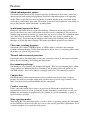
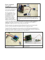
Hooking up the Sabertooth motor driver
All connections to the Sabertooth are done with screw terminals. This makes it easy to set up and
reconfigure your project. If you’ve never used screw terminal connections before, here is a quick
overview.
Step 1: Strip the wire which you are using
approximately ¼” The wires may be 12 gauge
to 30 gauge. Use thicker wire for high current
applications.
Step 3: Insert the stripped portion of the wire
into the opening in the screw terminal
Step 2: With a large screwdriver, turn the top
screw counter-clockwise until it stops gently.
Step 4: Turn the top screw clockwise until
you encounter resistance, then tighten the
screw firmly. Pull on the wire gently to ensure
that it is secured.
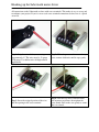
Battery Terminals
B+ and BThe battery or power supply is connected to
terminals B- and B+. B- connects to the
negative side of the battery (usually black.)
B+ connects to the positive side of the battery
The battery connects to terminals B+ and B(usually red or yellow.) It is usually best to
connect the battery through a connector instead of directly to the motor driver. This makes it
easy to unplug the battery for charging, and prevents plugging in the battery backwards.
Using a battery connector to connect/disconnect power to Sabertooth
Warning! Be very careful to wire and plug in the battery and
connector correctly. Connecting the battery backwards will destroy
the Sabertooth and will void the warranty.
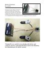
Motor Terminals
Motor 1 is connected to terminals M1A and
M1B as shown below. If the motor runs in
the opposite way that you want, you may
reverse the motor wires to reverse rotation.
Motor 2 is connected to terminals M2A and
M2B
The motors connect to terminals M1A/B and
M2A/B
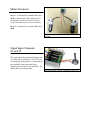
Signal Input Terminals
S1 and S2
The input signals that control the Sabertooth
are connected to terminals S1 and S2. If you
are running in analog mode, it is important to
have both the signal connected before
applying power to the device. Otherwise, the
motors may start unexpectedly.
The input signals connect to terminal S1 and/or S2
Power terminals
0V and 5V
The 0V and 5V connections are
used to power and interface to
low-power control circuits.
The 5V connection is a 5v
power output. This is useful
for supplying power to lowcurrent devices, such as a
The 5V terminal can be used to power small loads, like a
potentiometer or a radio
potentiometer or a radio receiver. The 0V signal must be
receiver. The 5v terminal is
connected to the ground of the device generating the input
capable of supplying 100
signal.
milliamps if the source battery
is 12.6v or less. If the source battery is greater than 12.6 volts, the 5v terminal is capable of
supplying 10 milliamps. If more power is needed, we recommend using a SportBEC or
DESW050 to supply the needed 5V power to the rest of the robot.
The 0V connection is the signal ground for the Sabertooth. In order to receive input signals
correctly, it must be connected to the ground of the device sending the signals.
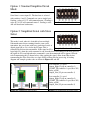
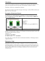
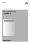
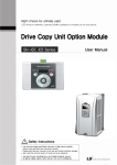
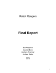
Using the 0V and 5v connections to power a radio receiver in R/C mode and potentiometer in
analog mode is shown in Figures 2.1 and 2.2. If you are using multiple Sabertooths running from
the same radio receiver, only one should have the 5v line connected.
Figure 2.1: Analog input using a potentiometer
powered from terminal 5V
Figure 2.2: R/C input using a receiver powered
from terminal 5V
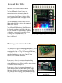
Status and Error LEDs
Sabertooth 2x25 has three indicator LEDs.
The blue LED marked Status1 is used to
communicate various information about the
current state. In most cases Status1 acts as a
power indicator. In R/C mode, it glows dimly if
there is no RC link present and brightly if there
is an RC link.
The blue LED marked Status2 is only used in
lithium mode. It blinks to indicate the number of
lithium cells detected.
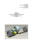
The red Error LED illuminates if the Sabertooth
has detected a problem. It will light if the driver
has shut down due to a depleted battery or due to
overheating, overcurrent or overvoltage. If you
All Status LEDs on
are using a NiCd or NiMH battery, and
commanding an acceleration causes the motor to jerk and the Error LED to flash on and off, the
battery is depleted.
Mounting your Sabertooth 2x25
The Sabertooth is supplied with four mounting holes. These
can be used to attach it to your robot. The centers of the
mounting holes form a 1.75” x 2.25” rectangle. The holes
are .125 inches in diameter. The proper size screw is a 4-40
round head machine or wood screw. Four 5/8” long
machine screws and nuts are included.
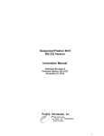
If your robot or device is constructed from insulating
materials such as wood or plastic, it may be necessary to
mount the Sabertooth on standoffs to allow air to circulate.
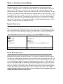
An example is shown in Figure 2.3
If your robot or device is constructed from metal, it is
usually better to attach the bottom heat spreader of the
Sabertooth directly to the frame, without standoffs. This
will allow your frame to act as a heat sink and will cause
the Sabertooth to run cooler. This is shown in Figure 2.4
Figure 2.3: Mounted to a wood
frame using standoffs
Figure 2.4: Mounted directly to a
metal frame
Operating Modes Overview
Mode 1: Analog Input
Analog input mode takes one or two analog inputs and uses those to set the speed and direction
of the motor. The valid input range is 0v to 5v. This makes the Sabertooth easy control using a
potentiometer, the PWM output of a microcontroller (with an RC filter) or an analog circuit.
Major uses include joystick or foot-pedal controlled vehicles, speed and direction control for
pumps and machines, and analog feedback loops.
Mode 2: R/C Input
R/C input mode takes two standard R/C channels and uses those to set the speed and direction of
the motor. There is an optional timeout setting. When timeout is enabled, the motor driver will
shut down on loss of signal. This is for safety and to prevent the robot from running away should
it encounter interference and should be used if a radio is being used to control the driver. If
timeout is disabled, the motor driver will continue to drive at the commanded speed until another
command is given. This makes the Sabertooth easy to interface to a Basic Stamp or other lowspeed microcontrollers.
Mode 3: Simplified serial.
Simplified serial mode uses TTL level RS-232 serial data to set the speed and direction of the
motor. This is used to interface the Sabertooth to a PC or microcontroller. If using a PC, a level
converter such as a MAX232 chip must be used. The baud rate is set via DIP switches.
Commands are single-byte. There is also a Slave Select mode which allows the use of multiple
Sabertooth 2x25 from a single microcontroller serial port.
Mode 4: Packetized serial
Packetized serial mode uses TTL level RS-232 serial data to set the speed and direction of the
motor. There is a short packet format consisting of an address byte, a command byte, a data byte
and a 7 bit checksum. Packetized serial automatically detects the transmitted baud rate based on
the first character sent, which must be 170. Address bytes are set via dip switches. Up to 8
Sabertooth motor drivers may be ganged together on a single serial line. This makes packetized
serial the preferred method to interface multiple Sabertooths to a PC or laptop. Because
Sabertooth uses the same protocol as our SyRen single motor drivers, both can use used together
from the same serial master.
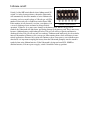
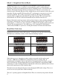
Lithium cutoff:
Switch 3 of the DIP switch block selects lithium cutoff. If
switch 3 is in the down position as shown the Sabertooth
will automatically detect the number of series lithium cells
at startup, and set a cutoff voltage of 3.0 volts per cell. The
number of detected cells is flashed out on the Status LED.
If the number of cells detected is too low, your battery is in
Lithium Cutoff enabled
a severely discharged state and must be charged before
operation. Failure to do so may cause damage to the battery pack. When 3.0V per cell is
reached, the Sabertooth will shut down, preventing damage to the battery pack. This is necessary
because a lithium battery pack discharged below 3.0v per cell will lose capacity and batteries
discharged below 2.0v per cell may not ever recharge. Lithium cutoff mode may also be useful to
increase the number of battery cycles you can get when running from a lead acid battery in noncritical applications. Because the system will continue to draw some power, even with the motor
shut down, it is important to unplug the battery from the Sabertooth promptly once the cutoff is
reached when using lithium batteries. If the Sabertooth is being run from NiCd, NiMH or
alkaline batteries, or from a power supply, switch 3 should be in the up position.
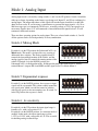
Mode 1: Analog Input
Analog input mode is selected by setting switches 1 and 2 to the UP position. Switch 3 should be
either up or down, depending on the battery type being used. Inputs S1 and S2 are configured as
analog inputs. The output impedance of the signals fed into the inputs should be less than 10k
ohms for best results. If you are using a potentiometer to generate the input signals, a 1k, 5k or
10k linear taper pot is recommended. In all cases, an analog voltage of 2.5V corresponds to no
movement. Signals above 2.5V will command a forward motion and signals below 2.5V will
command a backwards motion.
There are three operating options for analog input. These are selected with switches 4, 5 and 6.
All the options can be used independently or in any combination.
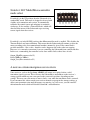
Switch 4: Mixing Mode
If switch 4 is in the UP position, the Sabertooth 2x25 is in
Mixed mode. This mode is designed for easy steering of
differential-drive vehicles. The analog signal fed into S1
controls the forward/back motion of the vehicle, and the
analog signal fed into S2 controls the turning motion of the
Switch 4: Mixed or independent
vehicle. If Switch 4 is in the DOWN position, the
Sabertooth 2x25 is in Independent mode. In Independent mode, the signal fed to S1 directly
controls Motor 1 (outputs M1A and M1B) and the signal fed to S2 controls Motor 2.
Switch 5: Exponential response
If switch 5 is in the DOWN position, the response to input
signals will be exponential. This softens control around the
zero speed point, which is useful for control of vehicles
with fast top speeds or fast max turning rates. If switch 5 is
in the UP position, the response is linear.
Switch 5: Exponential response
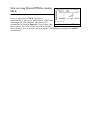
Switch 6: 4x sensitivity
If switch 6 is in the UP position, the input signal range is
from 0v to 5v, with a zero point of 2.5v.
If switch 6 is in the DOWN position, 4x sensitivity mode is
enabled. In this mode, the input signal range is from
1.875V to 3.125V, with a zero point of 2.5v. This is useful
for building analog feedback loops
Switch 6: 4x sensitivity
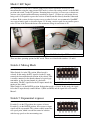
Note on using filtered PWM in Analog
Mode
If you are using a filtered PWM signal from a
microcontroller to generate the analog voltage, an R/C filter
with component values 10k ohms and at least .1uf is
recommended as shown in Figure 4.1. Using a larger value
Figure 4.1: Filtered PWM
filter capacitor such as 1uf or 10uf will result in smoother
motor operation, at a cost of slower transient response. A PWM frequency higher than 1000Hz is
recommended.
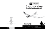
Mode 2: R/C Input
R/C input mode is used with a standard hobby Radio control transmitter and receiver, or a
microcontroller using the same protocol. R/C mode is selected by setting switch 1 to the DOWN
position and switch 2 to the UP position. If running from a receiver, it is necessary to obtain one
or more servo pigtails and hook them up according to figure 5.1. If there are only motor drivers
being used it is acceptable to power the receiver or microcontroller directly from the Sabertooth
as shown. If the system also has to power servos or other 5v loads, we recommend a SportBEC
or a receiver battery pack, as shown in figure 5.2. If using a receiver pack, do not connect power
to the 5V line of the Sabertooth because the maximum voltage it can tolerate is 6V.
Figure 5.1: R/C connection
Figure 5.2: R/C with a SportBEC set to 5V
There are three operating options for R/C mode. These are selected with switches 4, 5 and 6.
Switch 4: Mixing Mode
When Switch 4 is in the UP position, Mixed mode is
selected. In this mode, the R/C signal fed to the S1 input
controls the forward/backwards motion of the vehicle. This
is usually connected to the throttle channel of a pistol grip
transmitter, or the elevator channel of a dual stick
R/C Mixed or Independent
transmitter. The R/C signal fed to the S2 input controls the
turning of the vehicle.
When switch 4 is in the DOWN position, Independent mode is selected. In this mode, the signal
fed to the S1 input directly controls Motor 1 (M1A and M1B) and the signal fed to S2 controls
Motor 2.
Switch 5: Exponential response
If switch 5 is in the UP position, the response is linear.
If switch 5 is in the DOWN position, the response to input
signals will be exponential. This softens control around the
zero speed point, which is useful for control of vehicles
with fast top speeds or fast max turning rates.
Exponential mode enabled
Switch 6: R/C Mode/Microcontroller
mode select
If switch 6 is in the UP position, then the Sabertooth is in
standard R/C mode. This mode is designed to be used with
a hobby-style transmitter and receiver. It automatically
calibrates the control center and endpoints to maximize
stick usage. It also enables a Timeout Failsafe, which will
shut down the motors if the Sabertooth stops receiving
correct signals from the receiver.
Microcontroller mode selected
If switch 6 is set in the DOWN position, then Microcontroller mode is enabled. This disables the
Timeout Failsafe and auto-calibration. This means that the Sabertooth will continue to drive the
motor according to the last command until another command is given. If the control link is
possible unreliable – like a radio - then this can be dangerous due to the robot not stopping.
However, it is extremely convenient if you are controlling the Sabertooth from a microcontroller.
In this case, commanding the controller can be done with as little as three lines of code.
Output_High(Pin connected to S1)
Delay(1000us to 2000us)
Output_Low(Pin connected to S1)
A note on certain microprocessor receivers
Some receivers, such as the Spektrum AR6000, will output servo pulses before a valid
transmitter signal is present. This will cause the Sabertooth to autocalibrate to the receiver’s
startup position which may not correspond to the center stick position, depending on trim
settings. This may cause the motors to move slowly, even when the transmitter stick is centered.
If you encounter this, either consult your receiver manual to reprogram the startup position, or
adjust your transmitter trims until the motors stop moving. As a last resort, you can enter R/C
microcontroller mode which will disable Sabertooth’s autocalibration.
Mode 3: Simplified Serial Mode
Simplified serial uses TTL level single-byte serial commands to set the motor speed and
direction. This makes it easy to interface to microcontrollers and PCs, without having to
implement a packet-based communications protocol. Simplified serial is a one-direction only
interface. The transmit line from the host is connected to S1. The host’s receive line is not
connected to the Sabertooth. Because of this, multiple drivers can be connected to the same serial
transmitter. If using a true RS-232 device like a PC’s serial port, it is necessary to use a level
converter to shift the –10V to 10V rs-232 levels to the 0v-5v TTL levels the Sabertooth is
expecting. This is usually done with a Max232 type chip. If using a TTL serial device like a
microcontroller, the TX line of the microcontroller may be connected directly to S1.
Because Sabertooth controls two motors with one 8 byte character, when operating in Simplified
Serial mode, each motor has 7 bits of resolution. Sending a character between 1 and 127 will
control motor 1. 1 is full reverse, 64 is stop and 127 is full forward. Sending a character between
128 and 255 will control motor 2. 128 is full reverse, 192 is stop and 255 is full forward.
Character 0 (hex 0x00) is a special case. Sending this character will shut down both motors.
Baud Rate Selection
Simplified Serial operates with an 8N1 protocol – 8 data bytes, no parity bits and one stop bit.
The baud rate is selected by switches 4 and 5 from the following 4 options
2400 Baud: 01x00x
9600 Baud: 01x10x
19200 Baud: 01x01x
38400 Baud: 01x11x
What baud rate to use is dependent on what your host can provide and the update speed
necessary. 9600 baud or 19200 baud is recommended as the best starting points. If
communication is unreliable, decrease the baud rate. If communications are reliable, you may
increase the baud rate. The maximum update speed on the Sabertooth is approximately 2000
commands per second. Sending characters faster than this will not cause problems, but it will not
increase the responsiveness of the controller either.
The baud rate may be changed with power on by changing the DIP switch settings. There is no
need to reset or cycle power after a baud rate change.
There are 2 operating options for Simplified Serial. These are selected by the position of Switch
6.
Option 1: Standard Simplified Serial
Mode
Serial data is sent to input S1. The baud rate is selected
with switches 4 and 5. Commands are sent as single bytes.
Sending a value of 1-127 will command motor 1 Sending a
value of 128-255 will command motor 2. Sending a value
of 0 will shut down both motors.
Standard Simplified Serial
Option 2: Simplified Serial with Slave
Select
This mode is used when it is desirable to have multiple
Sabertooth motor drivers running from the same serial
transmitter, but you do not wish to use packetized serial. A
digital signal (0v or 5v) is fed to the S2 input. This is
controlled by the host microcontroller. If the signal on S2 is Simplified Serial with Slave Select
logic high (5v) when the serial command is sent, then the driver will change to the new speed. If
the signal on S2 is not high when the command is sent, then command will be ignored. Pseudocode demonstrating this is shown below. After sending the signal, allow about 50 us before
commanding the Slave Select line to a logic LOW to allow time for processing. A hookup
diagram and example pseudo-code are shown in Figures 6.2 and 6.3.
//set controller 1’s speed
Output_High (S2 pin on controller 1)
USART_TX(controller 1 speed, 0 to 255)
Delay_us(50)
Output_Low (S2 pin on controller 1)
//set controller 2’s speed
Output_High (S2 pin on controller 2)
USART_TX(controller 2 speed, 0 to 255)
Delay_us(50)
Output_Low (S2 pin on controller 2)
Figure 6.2: Hookup for Slave Select
Figure 6.3: Pseudocode for Slave Select
Mode 4: Packetized Serial Mode
Packetized Serial uses TTL level multi-byte serial commands to set the motor speed and
direction. Packetized serial is a one-direction only interface. The transmit line from the host is
connected to S1. The host’s receive line is not connected to the Sabertooth. Because of this,
multiple Sabertooth 2x25 motor drivers can be connected to the same serial transmitter. It is also
possible to use SyRen and Sabertooth motor drivers together from the same serial source, as well
as any other serial device, as long as it will not act on the packets sent to the Sabertooth. If using
a true RS-232 device like a PC’s serial port, it is necessary to use a level converter to shift the –
10V to 10V rs-232 levels to the 0v-5v TTL. Packetized serial uses an address byte to select the
target device. The baud rate is selected automatically by sending the bauding character (170 in
decimal, AA in hex) before any commands are sent.
Packet Overview
The packet format for the Sabertooth consists of an address byte, a command byte, a data byte
and a seven bit checksum. Address bytes have value greater than 128, and all subsequent bytes
have values 127 or lower. This allows multiple types of devices to share the same serial line.
An example packet and pseudo-code to generate it are shown in Figures 7.1 and 7.2
Void DriveForward(char address, char speed)
Packet
{
Address: 130
Putc(address);
Command : 0
Putc(0);
Data: 64
Putc(speed);
Checksum: 66
Putc((address + 0 + speed) & 0b01111111);
}
Figure 7.1: Example 50% forward
Figure 7.2: Pseudocode to generate 7.1
Baud Rate Selection:
Packetized Serial operates with an 8N1 protocol – 8 data bytes, no parity bits and one stop bit.
The baud rate is automatically calculated by the first character sent. This character must be (170
in decimal) (binary 10101010) and must be sent before any serial communications are done. It is
not possible to change the baud rate once the bauding character has been sent. The valid baud
rates are 2400, 9600, 19200 and 38400 baud. Until the bauding character is sent, the driver will
accept no commands and the green status1 light will stay lit. Please note that Sabertooth may
take up to a second to start up after power is applied, depending on the power source being used.
Sending the bauding character during this time period may cause undesirable results. When
using Packetized Serial mode, please allow a two-second delay between applying power and
sending the bauding character to the drivers.
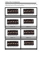
Address Byte Configuration:
Address bytes are set by switches 4, 5 and 6. Addresses start at 128 and go to 135. The switch
settings for the addresses are shown in the chart below
Address: 128
Address: 129
Address: 130
Address: 131
Address: 132
Address: 133
Address: 134
Address: 135
Commands:
The command byte is the second byte of the packet. There are four possible commands in
packetized serial mode. Each is followed by one byte of data
0: Drive forward motor 1 (decimal 0, binary 0b00000000, hex 0h00)
This is used to command motor 1 to drive forward. Valid data is 0-127 for off to full forward
drive. If a command of 0 is given, the Sabertooth will go into power save mode for motor 1 after
approximately 4 seconds.
1: Drive backwards motor 1 (decimal 1, binary 0b00000001, hex 0h01)
This is used to command motor 1 to drive backwards. Valid data is 0-127 for off to full reverse
drive. If a command of 0 is given, Sabertooth will go into power save mode for motor 1 after
approximately 4 seconds.
2: Min voltage (decimal 2, binary 0b00000010, hex 0h02)
This is used to set a custom minimum voltage for the battery feeding the Sabertooth. If the
battery voltage drops below this value, the output will shut down. This value is cleared at startup,
so much be set each run. The value is sent in .2 volt increments with a command of zero
corresponding to 6v, which is the minimum. Valid data is from 0 to 120. The function for
converting volts to command data is
Value = (desired volts-6) x 5
3: Max voltage (decimal 3, binary 0b0000011, hex 0h03)
This is used to set a custom maximum voltage. If you are using a power supply that cannot sink
current such as an ATX supply, the input voltage will rise when the driver is regenerating
(slowing down the motor) Many ATX type supplies will shut down if the output voltage on the
12v supply rises beyond 16v. If the driver detects an input voltage above the set limit, it will put
the motor into a hard brake until the voltage drops below the set point again. This is inefficient,
because the energy is heating the motor instead of recharging a battery, but may be necessary.
The driver comes preset for a maximum voltage of 30V. The range for a custom maximum
voltage is 0v-25v. The formula for setting a custom maximum voltage is
Value = Desired Volts*5.12
If you are using any sort of battery, then this is not a problem and the max voltage should be left
at the startup default.
4: Drive forward motor 2 (decimal 4, binary 0b00000100, hex 0h04)
This is used to command motor 2 to drive forward. Valid data is 0-127 for off to full forward
drive. If a command of 0 is given, the Sabertooth will go into power save mode for motor 2 after
approximately 4 seconds.
5: Drive backwards motor 2 (decimal 5, binary 0b00000101, hex 0h05)
This is used to command motor 2 to drive backwards. Valid data is 0-127 for off to full reverse
drive. If a command of 0 is given, the Sabertooth will go into power save mode after
approximately 4 seconds.
6: Drive motor 1 7 bit (decimal 6, binary 0b00000110, hex 0h06)
This command is used to drive motor 1. Instead of the standard commands 0 and 1, this one
command can be used to drive motor 1 forward or in reverse, at a cost of lower resolution. A
command of 0 will correspond to full reverse, and a command of 127 will command the motor to
drive full forward. A command of 64 will stop the motor.
7: Drive motor 2 7 bit (decimal 7, binary 0b00000111, hex 0h07)
This command is used to drive motor 2. Instead of the standard commands 4 and 5, this one
command can be used to drive motor 1 forward or in reverse, at a cost of lower resolution. A
command of 0 will correspond to full reverse, and a command of 127 will command the motor to
drive full forward. A command of 64 will stop the motor.
Mixed mode commands:
Sabertooth can also be sent mixed drive and turn commands. When using the mixed mode
commands, please note that the Sabertooth requires valid data for both drive and turn before it
will begin to operate. Once data for both has been sent, then each may be updated as needed, it is
not necessary to send both data packets each time you with to update the speed or direction. You
should design your code to either use the independent or the mixed commands. Switching
between the command sets will cause the vehicle to stop until new data is sent for both motors.
8: Drive forward mixed mode (decimal 8, binary 0b00001000, hex 0h08)
This is used to command the vehicle to drive forward in mixed mode. Valid data is 0-127 for off
to full forward drive.
9: Drive backwards mixed mode (decimal 9, binary 0b00001001, hex 0h09)
This is used to command the vehicle to drive backwards in mixed mode. Valid data is 0-127 for
off to full reverse drive.
10: Turn right mixed mode (decimal 10, binary 0b00001010, hex 0h0a)
This is used to command the vehicle to turn right in mixed mode. Valid data is 0-127 for zero to
maximum turning speed.
11: Drive turn left mixed mode (decimal 11, binary 0b00001011, hex 0h0b)
This is used to command the vehicle to turn leftt in mixed mode. Valid data is 0-127 for zero to
maximum turning speed.
12: Drive forwards/back 7 bit (decimal 12, binary 0b00001100, hex 0h0c)
This is used to command the vehicle to move forwards or backwards. A command of 0 will
cause maximum reverse, 64 will cause the vehicle to stop, and 127 will command full forward.
13: Turn 7 bit (decimal 13, binary 0b00001101, hex 0h0d)
This is used to command the vehicle turn right or left. A command of 0 will cause maximum left
turn rate, 64 will cause the vehicle to stop turning , and 127 will command maximum right turn
rate.
Checksum:
To prevent data corruption, each packet is terminated with a checksum. If the checksum is not
correct, the data packet will not be acted upon. The checksum is calculated as follows:
Checksum = address byte +command byte +data byte
The checksum should be added with all unsigned 8 bit integers, and then ANDed with the mask
0b01111111 in an 8 bit system.
Example of Packetized Serial:
The following is an example function for commanding two Dimension Engineering motor
drivers using Packetized Serial Mode. Figure 7.3 shows an example hookup and Figure 7.4
shows an example function.
Void DriveForward(char address, char speed)
{
Putc(address);
Putc(0);
Putc(speed);
Putc((address + 0 + speed) & 0b01111111);
}
Figure 7.3: Packetized serial hookup
Figure 7.4: Packetized Serial Function
Example: So in this function, if address is 130, command is 0 (for driving forward), speed is 64,
the checksum should calculate as follows:
130+0+64 = 194
194 in binary is 0b11000010
0b11000010 & 0b01111111 = 0b01000010
Once all the data is sent, this will result in the Sabertooth with address 130 driving forward at
roughly half throttle.
Emergency Stop:
In Packetized Serial mode, the S2 input is configured as an active-low emergency stop. It is
pulled high internally, so if this feature isn’t needed, it can be ignored. If an emergency stop is
desired, all the S2 inputs can be tied together. Pulling the S2 input low will cause the driver to
shut down. This should be tied to an emergency stop button if used in a device that could
endanger humans.