1
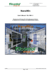
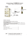
10623 Roselle Street, San Diego, CA 92121 C (858) 550-9559 C Fax (858) 550-7322
[email protected] C www.accesio.com
MODEL LVDT-8A
USER MANUAL
FILE: MLVDT8A.A1c
Notice
The inform ation in this docu me nt is pro vided for referen ce only. AC CE S does not assume any liability
arising out of the application or use of the information or products described herein. This document may
contain or reference information and products protected by copyrights or patents and does not convey any
license under the patent rights of ACCE S, nor the rights of others.
IBM PC, PC/XT, and PC/AT are registered trademarks of the International Business Machines
Corporation.
Printed in USA. Copyright 1995, 2006 by ACCES I/O Products Inc, 10623 Roselle Street, San Diego, CA
92121. All rights reserved.
WARNING!!
ALWAYS CONNECT AND DISCONNECT YOUR FIELD CABLING WITH
THE COMPUTER POWER OFF. ALWAYS TURN COMPUTER POW ER
OFF BEFORE INSTALLING A CARD. CONNECTING AND
DISCONNECTING CABLES, OR INSTALLING CARDS INTO A SYSTEM
WITH THE COMPUTER OR FIELD POWER ON MAY CAUSE DAMAGE
TO THE I/O CARD AND WILL VOID ALL WARRANTIES, IMPLIED OR
EXPRESSED.
2
Manual LVDT-8A
Warranty
Prior to ship me nt, AC CE S equipme nt is thoroug hly inspec ted and tested to applicab le spe cification s.
How ever, should eq uipm ent failure occ ur, AC CE S ass ures its cus tome rs that prom pt service a nd su pport
will be available. All equipment originally manufactured by ACCES which is found to be defective will be
repaired or replaced subject to the following considerations.
Terms and Conditions
If a unit is suspected of failure, contact ACCES' Customer Service department. Be prepared to give the
unit model number, serial number, and a description of the failure symptom(s). We may suggest some
simple tests to confirm the failure. We w ill assign a Return Material Authorization (RMA) numbe r which
must appear on the outer label of the return package. All units/components should be properly packed for
handling and returned with freight prepaid to the ACCES designated Service Center, and will be returned
to the customer's/user's site freight prepaid and invoiced.
Coverage
First Three Years: Returned unit/part will be repaired and/or replaced at ACCE S option with no charge for
labor or parts not excluded by w arran ty. Warran ty com me nce s with equ ipm ent shipm ent.
Following Years: Throughout your equipment's lifetime, ACCES stands ready to provide on-site or in-plant
service at reasonable rates similar to those of other manu facturers in the industry.
Equipment Not Manufactured by ACCES
Equipment provided but not manufactured by ACCE S is warranted and will be repaired according to the
terms and c onditions of the respective equipme nt manu facturer's warranty.
General
Under this Warranty, liability of ACCES is limited to replacing, repairing or issuing credit (at ACCES
disc retion) for any pro ducts w hich are proved to be defective during the wa rran ty pe riod. In no cas e is
ACCE S liable for consequential or special damage arriving from use or misuse of our product. The
customer is responsible for all charges caused by modifications or additions to ACCES equipment not
approved in writing by ACCE S or, if in ACCES opinion the equipment has been subjected to abnormal
use. "A bnorm al us e" for purposes of th is warra nty is defined as an y use to wh ich th e equipm ent is
exp ose d other than that use specified or intend ed a s evidenced by pu rcha se or sales repre sen tation.
Other than the above, no other warranty, expressed or implied, shall apply to any and all such equipment
furnished or sold by ACCES.
3
Manual LVDT-8A
Table of Contents
Chapter 1: Introduction . . . . . . . . . . . . . . . . . . .
Specifications . . . . . . . . . . . . . . . . . . . .
Figure 1-1: Block Diagram . . . . .
Installing the Hardw are . . . . . . . . . . . . .
Figure 1-2: Terminal Schematic .
.
.
.
.
.
.
.
.
.
.
.
.
.
.
.
.....
.....
.....
.....
.....
.
.
.
.
.
.
.
.
.
.
..
..
..
..
..
.
.
.
.
.
.
.
.
.
.
.
.
.
.
.
.....
.....
.....
.....
.....
.
.
.
.
.
.
.
.
.
.
..
..
..
..
..
.
.
.
.
.
.
.
.
.
.
.
.
.
.
.
.....
.....
.....
.....
.....
.
.
.
.
.
.
.
.
.
.
..
..
..
..
..
.
.
.
.
.
.
.
.
.
.
.
.
.
.
.
....
....
....
....
....
5
6
7
8
8
Chapter 2: Option Selection . . . . . . . . . . . . . . . . . . . . . . . . . . . . . . . . . . . . . . . . . . . . . . . . . . . . . . . . . . 9
Figure 2-1: Option Selection Map . . . . . . . . . . . . . . . . . . . . . . . . . . . . . . . . . . . . . . . . . . . 9
Chapter 3: Calibration . . . . . . . . . . . . . . . . . . . . . . . . . . . . . . . . . . . . . . . . . . . . . . . . . . . . . . . . . . . . . . 10
Ch apter 4 : Con nector Pin Ass ignm ents . . . . . . . . . . . . . . . . . . . . . . . . . . . . . . .
Table 4-1: Connector Pin Assignments, P1 . . . . . . . . . . . . . . . . . .
Table 4-2: LV DT Co nnections, C hannel 0 th rough Ch annel 7 . . . .
Tab le 4-3: Output P inouts . . . . . . . . . . . . . . . . . . . . . . . . . . . . . . .
Table 4-4: Power On Connections . . . . . . . . . . . . . . . . . . . . . . . . .
4
.
.
.
.
.
.
.
.
.
.
.
.
.
.
.
.
.
.
.
.
........
........
........
........
........
.
.
.
.
.
.
.
.
.
.
.
.
.
.
.
.
.
.
.
.
12
12
14
14
14
Manual LVDT-8A
Chapter 1: Introduction
Linear Variable Differential Transformers, LVDTs, are the most commonly used passive type displacement
transducers. The y operate und er the princip le of a m utua l induc tance chang e du e to m ove me nt of a magnetic
core. This movement produces an electrical output proportional to the displacement of the core.
An AC , 5KHz, 1.5 to 3.5VRMS excitation voltage, is applied to the primary winding (see the specification
section for other frequency options). Two identical secondary windings, symmetrically spaced from the
primary, are conn ected in a s eries-opp osing circu it. Motion of the magnetic core varies the mutual inductance
of each secondary to the primary, which in turn, determines the voltages induced from the primary to each of
the seco nda ries.
If the core is centered between the secondary windings, the voltage induced in the secondaries is identical
and 180 deg rees out-of-pha se, so there is no n et output. This is the N UL L po int. If the core is m ove d off
center, the mutual inductance of the primary with one secondary is greater than with the other, and an AC
differential voltage appears across the secondaries in series. For displacements within the operating range
of the transduc er used, this voltage is a linear a nalog of the displa cem ent.
Each LVDT -8A card supplies p ow er, excitation, and signal conditioning for up to eight independent LVDT
transduc ers..
Each LVDT Signal Processor Chip has an Oscillator that provides the Excitation voltage for the associated
Ch annels (0 through 7). This Excitation, or primary, voltage, designated as B voltage, is supplied to the LVDT.
The Signal Processor Chip also receives the VAC seco nda ry, or return, volta ge FR OM the LVDT . This
voltage is designated as the A voltage.
The Signal Processor Chip now executes the following equation.
Vout = A/B x 500uA x R2.
Vout is the VDC analog output for the channel selected.
A/B is the ratio of the secondary, IN, return VAC divided by the, OUT, VAC excitation voltage.
R2 is a scaling resistor. Changing the value of this resistor allows the setting of +/- 10 VDC
or +/- 5 VD C for full LVDT displa cem ent, or desired displac em ent.
The use of LV DT ratios ra ther than voltage leve ls alon e to determ ine the VD C chan nel outou ts
improves output stability especially against temperature changes.
ED Display Utility:
Six LE Ds a re used to display the VD C ou tput of a Jum per Selected chan nel, (0 throug h 7).
The LEDs are labeled +10V, +5V, ZERO, -5V, and -10V. Whenever the selected output voltage
is within +/- 0.5 volts of a Marked LED, that LED will be illuminated.
This Utility is not intended for Calibration. It may be used to facilitate testing of channel(s)
using On Card resources.
Do not install more than one jumper at a time, while the Card outputs are not affected, the LEDs
see the average of two cha nnels. On e Ju mper may b e ins talled, if de sired, w hen the C ard is
Under Use.
5
Manual LVDT-8A
The LVDT -8A has no inc om ing C om pute r com mu nications. It su pplies the eight V DC outoputs
as described above. If a channel is not used, no LVDT installed, that channel’s output will be
near zero volts.
Specifications
The LVD T-8 provides power, excitation, and signal conditioning for eight independent transducers.
•
Trans duce rs Served:
LVDT, RVDT, LVRT with primary impedances of 150 Ohms
or greater.
•
Excitation Frequency:
5 KHz.
The Frequencies may be anywhe re in the range of 1 to 10 KHz.
This is a Factory installed option.
•
Power Required:
+24 (18 to 36) VDC at 350 mA maximum
Call Factory for installed power options
Options Include:
+ 12 (9 to 18) VDC at 700 mA maximum
+ 48 (36 to 75} VDC at 175 mA maximum
External power supply: +/- 12 VDC or +/- 15 VDC at +/- 300 mA
maximum . If external power supply option is ordered, connect
+12VDC to terminal marked +24VDC, connect Ground as
marked and connect -12VDC to non-marked terminal. (See
Op tion S election m ap.)
•
Output Analog Voltage:
+/- 10 VDC or +/-5 VDC.
Environmental
•
Operating Temperature Range: 0 °C. to 65 °C.
•
Storage Temperature Range:
-40 °C. to +100 °C.
•
Hum idity:
0 to 90%, non-condensing.
•
Size (LVD T-8 m odule):
8.0" long (203 mm) X 4.74" wide (120 mm) X 0.75" high(19
•
Size (T-BO X):
mm). Fits inside of T-BOX enclosure (included)
8.5" long (216 mm) X 5.25" wide (133 mm) X 2.0" high (51
mm ).
6
Manual LVDT-8A
Figure 1-1: Block Diagram
7
Manual LVDT-8A
Installing the Hardware
The LVDT -8A is installed in a steel enclo sure (mo del T-BO X).
Signals from the transducers to the LVDT-8 module are connected via eight terminal blocks labeled TB1
through TB8. To ensure that there is minimum susceptibility to EMI, proper EMI cabling techniques
(twisted-pair wiring and, in extreme cases, shielded wiring) should be used on input wiring. Each of the
terminal blocks has five terminals:
1-2: Primary Winding
3-4: Secondary Winding
5: Chassis Ground
Figure 1-2: Terminal Schematic
The LVDT -8A boa rd req uires 350 mA of +24VDC pow er. Co nne ct the + 24V DC from your pow er supply to
terminal block TB9 Pin 3 (labeled +24V). Connect Power Ground to TB9 Pin 2 (labeled GND.) Under
normal circumstances, do not make ANY connections to TB9 Pin 1.
No te
To minimize possibility of extraneous noise, short terminals 3 and 4 on any unused inputs. DO NOT
ground the inputs or connect them to pin 5.
8
Manual LVDT-8A
Chapter 2: Option Selection
Output Channels
All eight output channels are continuously available from output terminals labeled TB10 and TB11. These
eight channels are also available from connector P1, pins 37 through 30.
External +24 VDC Power
A jumper block located between the ribbon cable connectors and terminal block TB1 are used to connect
+/- 12V powe r to the LVD T-8 . If com puter pow er carried by the ribbon cab le is u sed, the jum pers should
be placed in the PS positions. If any external power supply is used, then these jumpers should be placed
in the EX positions and the power supply connected to the adjacent screw terminals on TB1.
Figure 2-1: Option Selection Map
9
Manual LVDT-8A
Chapter 3: Calibration
Refer to the Block Diagram and Option Selection Map presented earlier in the manual for guidance as you
perform the calibration procedure.
Equipment Required
•
•
•
A means of m oving the LVDT sensor in precision increments across the desired range of
mo vem ent (a m icrometer jig).
An oscilloscope may be used to observe the primary and/or LVDT w aveforms.
A 4 ½ digit DVM should be used for reading VDC and VA C voltages.
Calibration Procedure
1.
Read LVDT Data Sheet. Note frequency Range, Input Voltage (Excitation), and Sensitivity (mV
out per disp laceme nt unit). Thes e eleme nts sh ould be com patible with the sim ilar elem ents
described below in step 2.
2.
Calibrating Cha nnel 0: S elect Ch anne l 0 by installing a LV DT at termina l block TB 2, See Figure
3-1 for locations. See the LVDT installation at Installing the Hardware, page 1-6. Set all four
positions of SW1 to OFF.. Set LVDT displacement to full mechanical scale or to desired
mechanica l sca le us ing the micrometer jig. W ith pow er O N re ad exc itation vo ltage, w hich sho uld
be 1.5 VRMS to 3.5 VRMS . Read return, secondary, voltage from LVDT at TB10, normal voltage
should fall between 0.15 volts and 3.5 volts at full mechanical displacement. If the excitation
voltage level is low turn on po sition 1 of SW1. The excitation voltage shou ld increase by a
nom inal 7 to 9% . Both the excitation voltage and the return voltage should be sine w ave s with
NO limiting at the top or bottom of the wave form.
3.
Scaling Output: See Figure 3-1for positions. A multi turn potentiometer, RP1 and a jumper position
JP2 are used to scale the VDC output, to either +/- 10 VDC or +/- 5VDC. For +/- 10VDC the
jumper at JP2 is installed at the bottom position or not installed at all. Adjust the LVDT to the
desired po sitive mechanica l pos ition, nominally full scale.. Turn the potentiom eter at R P1 until
the outpu t reads + 10.00 volts. A djust the LV DT to its null position . The output should be 0.0
volts. A djust the LV DT to the d esired ne gative position. The ou tput sh ould be - 10.00 volts. A
slight adjustment of potentiometer RP1 may provide better accuracy across the full plus and
min us scale.
4.
Failure to ca librate: N ot all LVDT s are alike. A LVDT may b e m is co nnected, or defective . It is
possible there is insufficient scale range for some LVDTs. You are invited to call the factory if you
have a LVDT-8A with a problem.
5.
After completing the calibration of Channel 0 the remaining seven channels may be installed and
calibra ted. It is sugge sted that this be done one channe l at a time.
6.
Chan 0 use TB1, RP1, JP2, and SW1; Chan 1 use TB2, RP4, JP3, and SW 2; Chan 2 use TB3,
RP7, JP6, and SW3: Chan 3 use TB4, RP8, JP8, and SW 4; Chan 4 use TB5, RP13, JP10, and
SW 5: Chan 5 use TB6, RP16, JP11, and SW6: Chan 6 use TB7, RP19, JP13, and SW6: Chan 7
use TB8, RP20, JP16, and SW8.
7.
The procedure for calibrating a channel other than Chan 0 is to use the same information from the
above steps, but using the symbol positions for the selected channel listed in step 6, above.
10
Manual LVDT-8A
8.
When all channels, or all channels to be used, are calibrated, it is suggested that the calibration of
all channels be reviewed. The LED Display Utility, see Introduction, can quickly locate a channel
that need s recalibration.
No te
Reverse the connections to terminals 3 and 4 if the LVDT direction is backwards from what you desire.
11
Manual LVDT-8A
Chapter 4: Connector Pin Assignments
Tw o parallel 37 pin D-S ub type conn ectors are provide d on the LVD T-8A module. Th e mating con nectors
are A MP type 7 473 04-1 or equivalent.
Pin#
1
2
3
4
5
6
7
8
9
10
11
12
13
14
15
16
17
18
19
20
21
22
23
24
25
26
27
28
29
30
31
32
33
34
35
36
37
Label
Used for
FACTORY
(UNUSED)
(UNUSED)
(UNUSED)
(UNUSED)
(UNUSED)
(UNUSED)
(UNUSED)
(UNUSED)
(UNUSED)
GROUND
(UNUSED)
(UNUSED)
(UNUSED)
(UNUSED)
(UNUSED)
(UNUSED)
GROUND
(UNUSED)
GROUND
“”
""
""
""
""
""
(UNUSED)
(UNUSED)
CH 7
CH 6
CH 5
CH 4
CH 3
CH 2
CH 1
CH 0
GROUND
GROUND
FACTORY
GROUND
OUTPU T
OUTPU T
OUTPU T
OUTPU T
OUTPU T
OUTPU T
OUTPU T
OUTPU T
TO
TO
TO
TO
TO
TO
TO
TO
A/D
A/D
A/D
A/D
A/D
A/D
A/D
A/D
CHA NNEL
CHA NNEL
CHA NNEL
CHA NNEL
CHA NNEL
CHA NNEL
CHA NNEL
CHA NNEL
7
6
5
4
3
2
1
0
Table 4-1: Connector Pin Assignments, P1
12
Manual LVDT-8A
Pin #
Label
Use
1
- Excitation
Ne ga tive, B Ch an ne l, Ex citatio n fo r Ch an ne l 0
2
+ Excitation
Po sitive , B C ha nn el, E xcita tion fo r Ch an ne l 0
3
+ Input
Po sitive , A C ha nn el, R etu rn s igna l from Ch an ne l 0
4
- Input
Ne ga tive, A Ch an ne l, Re turn sign al from Ch an ne l 0
5
GROUND
TB1
TB2
1
- Excitation
Ne ga tive, B Ch an ne l, Ex citatio n fo r Ch an ne l 1
2
+ Excitation
Po sitive , B C ha nn el, E xcita tion fo r Ch an ne l 1
3
+ Input
Po sitive , A C ha nn el, R etu rn s igna l from Ch an ne l 1
4
- Input
Ne ga tive, A Ch an ne l, Re turn sign al from Ch an ne l 1
5
GROUND
TB3
1
- Excitation
Ne ga tive, B Ch an ne l, Ex citatio n fo r Ch an ne l 2
2
+ Excitation
Po sitive , B C ha nn el, E xcita tion fo r Ch an ne l 2
3
+ Input
Po sitive , A C ha nn el, R etu rn s igna l from Ch an ne l 2
4
- Input
Ne ga tive, A Ch an ne l, Re turn sign al from Ch an ne l 2
5
GROUND
TB4
1
- Excitation
Ne ga tive, B Ch an ne l, Ex citatio n fo r Ch an ne l 3
2
+ Excitation
Po sitive , B C ha nn el, E xcita tion fo r Ch an ne l 3
3
+ Input
Po sitive , A C ha nn el, R etu rn s igna l from Ch an ne l 3
4
- Input
Ne ga tive, A Ch an ne l, Re turn sign al from Ch an ne l 3
5
GROUND
TB5
1
- Excitation
Ne ga tive, B Ch an ne l, Ex citatio n fo r Ch an ne l 4
2
+ Excitation
Po sitive , B C ha nn el, E xcita tion fo r Ch an ne l 4
3
+ Input
Po sitive , A C ha nn el, R etu rn s igna l from Ch an ne l 4
4
- Input
Ne ga tive, A Ch an ne l, Re turn sign al from Ch an ne l 4
5
GROUND
1
- Excitation
Ne ga tive, B Ch an ne l, Ex citatio n fo r Ch an ne l 5
2
+ Excitation
Po sitive , B C ha nn el, E xcita tion fo r Ch an ne l 5
3
+ Input
Po sitive , A C ha nn el, R etu rn s igna l from Ch an ne l 5
4
- Input
Ne ga tive, A Ch an ne l, Re turn sign al from Ch an ne l 5
5
GROUND
TB6
TB7
1
- Excitation
Ne ga tive, B Ch an ne l, Ex citatio n fo r Ch an ne l 6
2
+ Excitation
Po sitive , B C ha nn el, E xcita tion fo r Ch an ne l 6
3
+ Input
Po sitive , A C ha nn el, R etu rn s igna l from Ch an ne l 6
13
Manual LVDT-8A
4
- Input
Ne ga tive, A Ch an ne l, Re turn sign al from Ch an ne l 6
5
GROUND
1
- Excitation
Ne ga tive, B Ch an ne l, Ex citatio n fo r Ch an ne l 7
2
+ Excitation
Po sitive , B C ha nn el, E xcita tion fo r Ch an ne l 7
3
+ Input
Po sitive , A C ha nn el, R etu rn s igna l from Ch an ne l 7
4
- Input
Ne ga tive, A Ch an ne l, Re turn sign al from Ch an ne l 7
5
GROUND
TB8
Tab le 4-2: LV DT Co nnections, C hannel 0 th rough Ch annel 7
Pin #
Label
Use
Outputs/TB10
1
CH 0
2
GND
3
CH 1
4
GND
5
CH 2
6
GND
7
CH 3
8
GND
VD C S igou t-0 fo r Ch an ne l 0
VD C S igou t-1 fo r Ch an ne l 1
VD C S igou t-2 fo r Ch an ne l 2
VD C S igou t-3 fo r Ch an ne l 3
Outputs/TB11
1
CH 7
2
GND
3
CH 6
4
GND
5
CH 5
6
GND
7
CH 4
8
GND
VD C S igou t-7 fo r Ch an ne l 7
VD C S igou t-6 fo r Ch an ne l 6
VD C S igou t-5 fo r Ch an ne l 5
VD C S igou t-4 fo r Ch an ne l 4
Table 4-3: Ou tput P inouts
Pin #
Label
Use
2 4 VD C
1 2 VD C
4 8 VD C
+ /- 12 V D C
1
+24V
+24 VDC Input
+12 VDC
+48 VDC
+12 VDC
2
GND
+24 VD C G roun d R eturn
GND
GND
GND
3
TB9
M A K E N O C O N N E CT IO N
No Connection
No Connection
- 12 V D C
Table 4-4: Power On Connections
14
Manual LVDT-8A
Customer Comments
If you experience any problems with this manual or just want to give us some feedback, please email us
at: [email protected]. Please detail any errors you find and include your mailing address so that we
can send you any manual updates.
10623 Roselle Street, San Diego CA 92121
Tel. (858)550-9559 FAX (858)550-7322
www.accesio.com
15
Manual LVDT-8A