1
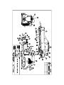
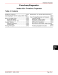
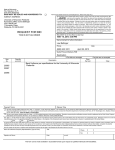
Machine Specification and User Manual
16-30" Pipe Bending Machine
S/N: 399
Table of Contents
I
Introduction
Orientation
Major Components
Pin-up Shoe
Clamps
Stiffback
Tongue
Pipe Rollers
Controls
Stiffback Control Valve
Pin-up Control Valve
Winch Control Valve
Pressure Control
II
Operation
Pre-Starting Checks
Starting
Pipe Loading
Mandrel to Die Reference
Bending Reference
Pull interval index
Pipe leveling reference
Pipe bending reference
Production Operation
Shut Down Procedure
Bending and Operating Problems
III
4
4
5
5
6
6
6-7
7
7-8
8
8-9
Maintenance
Lubrication
Engine
Bushings
Hydraulic Tank
Pin-up Wedge
Pipe Size Change Over
IV
1
1
1
1-2
2
2
2
2
2
2
2
3
10
10
10
10
10
10
Safety
Safety summary
11-12
I. Introduction
This machine was designed and built to bend sixteen through thirty inch pipe. It should not be
use to straighten crooked or bent pipe. It should not be used to bend pipe that is bent or crooked.
Orientation
The enclosed drawing of the 16-30 PBM has encircled part numbers, each of which refers to a
machine part or detail. Refer these identifying numbers from this manual and the enclosed parts
list.
The operating controls and operators platform are on the side from which the machine is
operated. With the operator standing on the platform facing the machine, the front of the
machine or stiffback end of the machine is to the left, the rear of the machine, or pinup shoe end
is to the right.
Major components
The Hydraulic power system consists of a Vickers hydraulic pump directly driven by a CAT
diesel engine. This hydraulic pump supplies the hydraulic power for all the cylinders and for the
hydraulic winch motor.
The Pinup Shoe This is the fabricated shoe in the rear of the machine which supports the pipe
while bending. The shoe rest on a base which slides on the wedge when the pinup cylinder is
actuated.
Clamps The clamps are hinged to the top of the pinup and are powered by the clamp
1
cylinder that is connected to the stiffback hydraulic circuit. When the stiffback is in use the
clamps close. When the stiffback is lowered the clamps open. The clamps keep pipe from
getting out-of-round while bending.
Stiffback The stiffback is an integral part of the machine. It is actuated by four cylinders, two
outboards, and two inboards. The inboard cylinders are actuated first by the hydraulic systme to
force the pipe into the die. When the pressure increases and movement of the cylinders
decreases, the outboard cylinders are automatically moved up to furnish the leverage required to
bend the pipe.
Tongue The tongue is attached to the front bottom side of the stiffback. It is used in
conjunction
with the tractor draw bar to move the machine from one location to the other.
Pipe Rollers The front roller is attached to the tongue, the rear roller is attached to the frame
between the stiffback and the pinup. When the rollers are properly positioned and the stiffback
are down the pipe rest on the rollers and not on the stiffback - thus permitting easy movement of
the pipe through the machine.
The Controls
Stiffback Control Valve This valve is to the operators rights. Pushing the valve lever forward
moves the stiffback into the up position. Pulling the valve handle back return the stiffback into
the down position.
Pinup Control Valve Pushing the valve handle forward moves the pinup shoe up. Pulling the
handle back moves the pinup back to the down position
Winch Control Valve Pushing the valve handle forward will cause the winch to wind. Pulling
the valve handle back will cause the winch to unwind.
2
Pressure Control The Hydraulic relief valve controls the maximum hydraulic pressure in the
system. The pressure can be adjusted to any pressure within the valve range.
3
II. Operation
Pre-Starting Checks
1. Check oil in engine
2. Check water in engine
3. Check air cleaner
4. Check water in battery
5. Check fuel level in fuel tank
6. Check pipe roller setting. The top center of the rollers should be set slightly higher than the
bottom curve of the stiffback liner when the stiffback is in the down position.
7. Check tension on the coil spring under the stiffback. The tension is adjusted by tightening or
loosening the turnbuckle.
8. Check the oil level in the hydraulic tank. When all cylinders are in the down positions.
Starting
Follow engine manufacturers recommendation for starting and operating the engine. The
instrument panel and throttle are located for easy access at operators position. After starting,
allow hydraulic oil to circulate at moderate speed until it flows freely. When operating
temperature has been reached, hydraulic system will operate more quietly than when cold
Engine RPM should ne adjusted according to pipe wall thickness being bent. For heavy wall
pipe, engine should be turning 2200 RPM. For thin wall pipe, engine should be turning at 2000
RPM.
4
Pipe Loading
1. Lower stiffback and pin-up to accept pipe.
2. Pipe is loaded through rear whenever mandrel is to be used; however, if mandrel is not to be
used, load pipe through front of bender.
3. Sideboom should slightly raise the rear of the pipe so that the upper surface touches the die,
and the lower front edge is on the stiffback. The purpose of this is to allow easy entry on the
mandrel
4. Using manual controls, drive the mandrel into the pipe.
5. Sideboom should lower pipe to the level position and move it further inside the bending
machine, but not beyond the front edge of the die. This is to ensure easy viewing of the mandrel
when establishing its location under the die.
Mandrel to Die Reference
The mandrel must be accurately positioned beneath the die and remain in the same position
during each bend. If the mandrel is not properly positioned pipe wall buckling or other damage
will occur. Since the mandrel is not clearly visible during operation an external reference must
be used to locate mandrel. This can be done by stacking the end of the bending machine and
stacking the end of the mandrel reach rod and aligning the reach rod with the stack marker
during
each bend. Sideboom may have to release pipe at rear and move around to the front of the
machine to support the pipe as it is being winched through. Otherwise, pipe will be unbalanced
and tilt.
5
Bending References
After mandrel positing references have been established, three other references must be
established and marked: (1) Index for pull interval marks, (2) Pipe leveling references, and (3)
Pipe bending references. The first reference mark is used to align intervals marked on pipe. The
second mark is used as a starting point to begin measuring the amount of bend. The third mark
represents the number of degrees/bend. Leveling and bending references are marked on a
calibrated rod on the front of the machine.
Pull interval index During the bending process, pipe is moved at
predetermined interval with the bender. Intervals are marked, with chalk or a
grease pencil, along the side of the pipe for easy viewing by the operator. To
move the pipe at equal distances a mark should be made on the stiffback line so
the reference marks on the pipe can be aligned with it.
Pipe leveling reference The amount which pipe is bent during each pull. Mark is
determined between two reference marks, leveling reference and bend reference.
Both references are to be established and marked on a rod that extends upward
from the outboard cylinder operator side. Proceed as follows.
Note: It is assumed that pipe has been moved through the machine until the tail
end of the pipe with the rear of the bending machine. There is an
unbendable area at each end of the pipe. Egging may occur if bending is
attempted in these areas.
1. Level pipe in bending machine
A. Move stiffback valve forward carefully until stiffback raises pipe
against die slightly
6
B. Move Pin-up valve forward, causing pin-up shoe to move up against
the pipe.
C. Measure distance from lower front edge of die to top of pipe between
rear lower edge of die and top of pipe. Compare the measurements.
First dimension should be 1/4" less than measurement taken at rear of die.
This is to cause pipe to start bending from the middle of the die forward.
If front dimension is greater, lower pin-up shoe slightly, snug stiffback up,
and re-measure. Repeat until level position is obtained,.
When pipe level, mark calibrated rod where is emerges through the guide
tube.
Pipe Bending References Bending references can be established as follows:
1. Raise pipe to level position. The stiffback valve lever is moved forward until lever
reference mark on rod moves slightly above opening in guide tube. Release to hold
stiffback in position. Pin-up liver is moved forward until pin-up moves firmly against
pipe the released to hold pin-up position.
2. When pipe is level, begin bending in small increments until desired amount of bend is
obtained.
Production operation
With bending references established, begin production bending process.
1. Have helper pull winch cable out to end of pipe so it can be advanced by the winch.
2. With stiffback and pin-up down, use mandrel valve to move pipe until number two
interval mark aligns with index mark on stiffback.
3. Reposition mandrel under die.
4. Expand mandrel
7
5. Level pipe using stiffback and pin-up and leveling mark as a reference.
6. Bend pipe using stiffback valve and bending mark as a reference.
7. Lower stiffback, pin-up and mandrel and verify pipe is bent correctly.
8. After pipe has been bent satisfactorily, remove it through rear of machine similar to the
method used in loading it. Before pipe is completely removed raise outer most end
slightly so that mandrel operator may remove the mandrel.
9. Repeat steps 1-8 for remaining pipe joints.
Shut down procedure Return pin-up and stiffback to the down position and turn engine off.
Bending and Operating Problems Common bending problems and remedies.
1. Pipe egging is caused by excessive compression at one place. Lengthen bend out of
possible and check to make sure pipe is being bent in front half of die.
2. Buckling of pipe may be caused by excessive bending or an improper procedure. If a
proper procedure has been followed and a buckle develops, double check procedure.
Other causes of buckling are (1) wave in pipe wall, (2) dented pipe, (3) inconsistent wall
thickness, and (4) variation of hardness of pipe.
3. If die is marking side of pipe in bending, then die is improperly lined up with stiffback
and pin-up.
4. If pipe being bent shown excessive scratching check the following: 1. Leading edges of
pin-up, stiffback and die for sharp edges. 2. Variation in hardness of pipe. 3. Tractor
holding straight with machine while bending 4. Wave in pipe wall.
5. Pin up wedges slipping-remove excess oil and roughen surface of wedges.
8
6. Rollers that are set too high will be damaged in bending or will damage pipe. Rollers
that are set too low are useless and make moving pipe through machine difficult.
7. Packing glands that are leaking oil should be tightened down evenly. If leakage is not
stopped remove seal retainer and place shim between it and packing, then re-tighten.
8. If stiffback is raised too high pistons in the cylinder may pass bypass port and stick
there. With engine shut off, a weight such as a tractor boom laid on the tongue will
cylinder back to operating position.
9
III. Maintenance
Lubrication
Engine. Check crankcase oil and level daily. Change oil and filter as described in
manual.
Bushings. Use grease gun on roller shafts and other fittings daily.
Hydraulic Tank. Check hydraulic fluid level in tank daily. Condition of hydraulic
return line filter should be checked daily.
Pin-up Wedge. Oil top of wedge sparingly. Too much oil may cause wedge to slip
during
bending
Pipe size change-over
To change from 30 inch pipe to a smaller size, a new die, stiffback liner (two pieces),
pipe clamp liner (two pieces) and pin-up liner must be installed this is known as a
bending set.
1. To gain access for other task remove die first, use hand winch above die to lower it and
slide it out the stiffback end.
2. Install rear stiffback liner and secure it down with the hold downs located on the
stiffback.
3. Installation of the front stiffback liner is the same as the rear.
4. Install pin-up liner and secure it with holds.
5. Install clamp liners and secure with bolts.
6. Install die of proper size. When the die is slid back under the die nest it is to be raised
using the hand winch and then secured.
10
IV. Safety
The following are general safety precautions and are instruction that people must
understand and apply during the operation and maintenance of the equipment to ensure personal
safety. User is responsible for providing safety equipment.
Warning and Caution Statements Warning and caution statements have been placed
throughout
this text prior to operation or maintenance procedures. A warning and or caution will apply each
time the related step is repeated. Prior to starting any task, the warnings or cautions included in
the text will be reviewed and understood.
Electrical circuits Operating personnel must think at all times. Do not replace or make
adjustments inside equipment with the electrical power turned on. Under certain conditions,
danger may exist with the power supply turned off due to charge capacitors. To avoid injury
always remove the power, dry charge and ground circuit before touching. Always be sure all
electrical equipment is properly grounded.
Do not service alone Do not attempt service unless another person capable of rendering aid is
present.
Resuscitation Personnel working with or near dangerous voltage should be trained in methods
of resuscitation.
Cleaning/Chemical/Primers Some cleaners, chemical, paints, and primers have adverse effects
on skin, eyes, and the respiratory tract. Observe warning labels.
Compressed air Use of compressed air can create an environment of propelled particles. Do
11
not direct air stream towards self or any other person.
Dangerous pressures Pressure systems apply to all ranges of pressure. Care must be taken
during
testing to ensure that all connection are proper and tight prior to applying pressure to test units.
Lifting/handling Use only equipment rated above maximum load to be lifted. Use adequate
number of personnel or appropriately rated lifting devices to move equipment.
Hearing safety Prolonged exposure to loud noise can cause impairment or loss of hearing.
Wear
suitable hearing protective device to protect against loud noise.
Batteries Keep sparks and flames away from batteries. Before you connect or disconnect a
battery charger, turn off charge.
Safety Equipment Wear safety equipment and fairly tight clothing when working with or near
moving parts, hot parts, pressurized systems, electrical systems, or fuel systems.
Safety warnings with Pipe Bending Machine
Always work at ends of pipe, never between or in front of rolling pipe.
Stay clear of pipe while rollers are operating.
Do not operate travel car until personnel are clear of tracks.
Only qualified personnel should attempt to operate or maintain equipment.
Do not operate roller assemblies until all personnel are clear of pipe.
Do not open chamber access doors until all chamber activity has ceased.
Keep sparks and open flame away from dust collector.
12
PARTS ORDERING PROCEDURES
1.
From the parts list in the manual state part number and description.
2.
State quantity of each item you will be purchasing.
3.
State your company name and address for invoicing.
4.
State method of delivery you desire and address, if different than invoicing address.
5.
State purchase order number.
ORDER PARTS 24 HOURS A DAY SEVEN DAYS A WEEK. PHONE, FAX OR EMAIL.
DMI INTERNATIONAL, INC.
15715 East Pine Street
Tulsa, Oklahoma 74116
918-438-2213 Phone
918-234-9376 Fax
[email protected] E-Mail
PARTS ORDER FORM
TO ORDER REPLACEMENT PARTS FOR YOUR DMI
INTERNATIONAL, INC. EQUIPMENT PLEASE COMPLETE THE
INFORMATION BELOW.
1.
COMPANY NAME AND ADDRESS
__________________________________________________________________
__________________________________________________________________
2.
PART NAME AND NUMBER
__________________________________________________________________
__________________________________________________________________
3.
QUANTITY
__________________________________________________________________
4.
EQUIPMENT SIZE AND MODEL NUMBER
__________________________________________________________________
__________________________________________________________________
5.
TYPE OF DELIVERY
__________________________________________________________________
IN ORDER TO SERVE OUR CUSTOMER WITH PROMPTNESS AND
EFFICIENCY WE ASK THAT THE QUESTION ABOVE TO BE
ANSWERED WHETHER ORDERING BY FAX OR CALL IN.
DMI INTERNATIONAL, INC.
15715 EAST PINE STREET
TULSA, OKLAHOMA 74116
918-438-2213 PHONE
918-234-9376 FAX