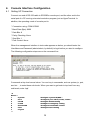
1
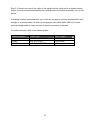
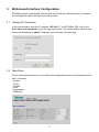
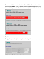
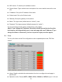
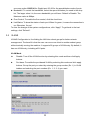
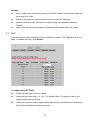
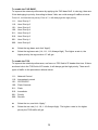
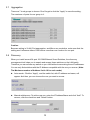
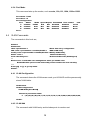
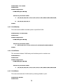
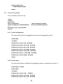
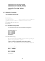
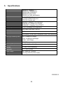
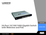
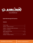
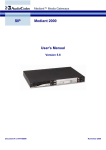
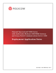
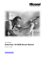
User’s Manual
EtherFast 10/100M Smart Switch
Model No.: SP659B
http://www.micronet.info
Table of Content
-------------------------------------------------------------------------------------------------------------------------
1.
INTRODUCTION............................................................................................ 3
1.1
1.2
1.3
2.
INSTALLATION.............................................................................................. 5
2.1
2.2
2.3
2.4
3.
SETTING UP CONNECTION ....................................................................... 7
MAIN MENU ............................................................................................. 7
SYSTEM .................................................................................................. 8
PORTS .................................................................................................... 9
VLANS ................................................................................................. 10
QOS ..................................................................................................... 11
AGGREGATION ....................................................................................... 13
DISCOVERY ........................................................................................... 13
CONSOLE INTERFACE CONFIGURATION............................................... 14
4.1
4.2
4.3
4.4
4.5
4.6
4.7
4.8
5.
PREPARING THE SITE ............................................................................... 5
SETTLING THE SWITCH ............................................................................. 5
CONNECTING TO POWER .......................................................................... 5
CONNECTING TO NETWORK ...................................................................... 5
WEB-BASED INTERFACE CONFIGURATION ............................................ 7
3.1
3.2
3.3
3.4
3.5
3.6
3.7
3.8
4.
PACKAGE CONTENTS ............................................................................... 3
FEATURES ............................................................................................... 3
PHYSICAL DESCRIPTION ........................................................................... 4
SETTING UP CONNECTION ..................................................................... 14
SYSTEM COMMANDS .............................................................................. 15
PORT COMMANDS .................................................................................. 16
VLAN COMMANDS ................................................................................. 18
TRUNK COMMANDS ................................................................................ 20
BANDWIDTH COMMANDS ........................................................................ 21
QOS COMMANDS ................................................................................... 22
LOGOUT COMMANDS .............................................................................. 23
SPECIFICATIONS ....................................................................................... 24
2
1.
Introduction
Micronet SP659B is a 24 ports 10/100M plus 2 ports Gigabit smart switch. It provides
powerful, high-performance Ethernet Smart Switch, with 2 ports capable of 10, 100 and
1000Mbps for allowing you to keep up with expending network needs. The switch is
plug-n-play and also fully compliant with all kinds of network protocols.
Compared with ordinary dumb switches, the 24+2G ports Smart Switch embeds advanced
management capability, like port trunk, VLAN and QoS and can be managed through
console port or web-based UI. Moreover, it also supports auto-discovery function,
auto-negotiation for speed and duplex mode.
1.1
Package Contents
Verify your package contains the following items:
z EtherFast 10/100M Smart Switch
z Quick Installation Guide
z Manual CD
z RS-232 cable
z Rack-mount brackets
z Rubber foot and screws
z Power cord
1.2
Features
Micronet SP659B provides the following features:
z Compliant with IEEE802.3 10Base-T, IEEE802.3u 100Base-TX, IEEE802.3ab
1000Base-T, IEEE 802.3x flow control, IEEE802.1p traffic prioritization standards
z Provide auto-negotiation function to automatically select optimal speed
(10/100/1000Mbps) and mode (Full/Half Duplex)
z Support 26 groups of port-based VLAN
z Support 7 groups of port trunk and up to 4 ports per trunk
z Support Port-based, tag-based and TOS to achieve QoS priority
z Support per-port bandwidth control
z Provide local console port or web-based interface for configuration
z Provide auto-discovery function for easy network management
z Support auto uplink, no more cross-over cable
z Support forward and filter packets at non-blocking, full wire speed
z 100 - 240V AC, full range internal power supply
3
1.3
Physical Description
SP659B front view
Please refer to the following table for LED definition
10/100M (1-24 port)
LED
Status
Operation
POWER
On
Power is on.
Off
On/Green
Blink/Green
Off
Power is off.
Connection established.
Transmitting or receiving data.
No link.
LNK/ACT
10/100/1000M (25, 26 port)
LED
Status
Operation
1000M
On/Green
1000M connection established.
100M
10M
On/Green
On/Green
100M connection established.
10M connection established.
ACT
Blink/Green
Transmitting or receiving data.
4
2.
Installation
2.1
Preparing the Site
Select the site that meets the following requirements:
Characteristic
2.2
Requirement
Temperature
32 to 104˚F (0 to 40˚C)
Humidity
10% ~ 90%, non-condensing
Settling the Switch
z Mounted to 19-inch standard rack
Locate the accessories provided in the product package. Use the rack-mount brackets and
screws to install the switch into any EIA 19” standard rack.
Step 1: Attach the brackets to each side of the chassis.
Step 2: Apply the screws to each side and secure them tightly.
Step 3: Carefully position the switch into the rack.
Step 4: Align the brackets to the side holes on the rack and use rack screws to secure the
chassis with the rack.
z Desktop or any flat surface
The switch can sit on desktop or any flat surface with adequate space and ventilation. If
you want to place it onto a shelf, make sure the shelf can withstand the weight of the
switch.
Step 1: Simply put the switch on the desired place.
Step 2: Ensure the switch receives good ventilation.
Step 3: Proceed to the “Connecting to Power” section.
2.3
Connecting to Power
Locate the provided AC power cord.
Step 1: Connect the AC power cord to the receptacle at the back of the switch.
Step 2: Attach the plug into a standard AC outlet with a voltage ranging from 100 to 240
VAC.
Step 3: The power LED on the front panel will come on then.
2.4
Connecting to Network
Step 1: First, ensure the power of the switch (and end devices) is turned off.
L It may cause electric shock or any possible harm to you if the power is not switched off.
Step 2: Prepare cable with corresponding connectors for each type of port in use.
5
Step 3: Connect one end of the cable to the switch and the other end to a desired device.
Step 4: Once the connections between two end-devices are made successfully, turn on the
power.
In making a switch interconnection, you could use any port to connect another switch with
straight or crossover cable. As all the ports support auto-uplink (MDI / MDI-X) function,
using a straight cable to make a switch-to-switch connection is allowed.
For cable selection, refer to the following table:
Network Speed
10M
100M
1000M
Cable Type
Cat. 3, 4, 5 UTP/STP
Cat. 5 UTP/STP
Cat. 5, 5e UTP/STP
6
Max. Length
100 meters
100 meters
100 meters
3.
Web-based Interface Configuration
SP659B provides a web-based interface and one RJ-45 port, allowing users to configure
and manage the switch remotely from web browser.
3.1
Setting UP Connection
In the web browser, enter the IP address “192.168.1.1” as SP676BA’s URL. Key in the
User name and Password to pass the login step below. The factory default value of User
Name and Password is “admin”. And then, you can enter the main page.
3.2
Main Menu
On the main page as below, you can select the configuration section by clicking the menu
tabs. It includes:
* System
* Ports
* VLANS
* QoS
* Aggregation
* Discovery
7
To restore the default values of switch, click the “Default” Button. If you want to restart the
switch, click the “Reboot” Button. To check the connection status of each port from 1 to 16,
take a look at the port monitor. When the port is connected, it is green. Otherwise it’s red.
3.3
System
To set up the items on the System configuration such as login ID, password, system name,
and IP information.
z Mac address: The Mac address of the switch.
8
z S/W Version: To check up the software version.
z System Name: Type a switch name and replace the current switch name with a new
one.
z IP Address: Set up the IP address of the switch.
z Subnet mask: Set up the Subnet mask.
z Gateway: Set up the gateway in this subnet.
z Name: The login name (default name is “admin”). save
z Password: The login password (default password is “admin”).
To save the change of the system configurations, click “Apply”.
(Note: IF you change the IP address, the switch will be rebooted by itself and the
web browser will automatically open a new web page with new IP address. IF you
change the Name or Password, you have to process login procedure again.)
3.4
Ports
To set up the items on the Port configuration such as speed/duplex mode, FDX flow
control.
z Admin: Enable or disable the administration function to configure the web page in
specific port.
z Operation mode: Choose AUTO, 10Half, 10Full, 100Half or 100Full for port 1~24 and
9
one more option 1000Full for Gigabit port 25~26 for the speed/duplex mode of ports.
z Bandwidth: To control the bandwidth, select the speed limitation you need in the drop
list. The larger value it is, the more bandwidth you will have. Default is Disable. The
Maximum value is 8Mbps.
z Flow Control: To enable the flow control, click the check box.
z Link/Status: To show the status of each port. When it’s green, it means the connection is
up. Otherwise, it’s red.
To save the change of the system configurations, click “Apply”. To get back to the last
settings, click “Refresh”.
3.5
VLANS
VLANS Configuration is for dividing the LAN into subnet groups for better network
management. The benefit is that the user can move one client to another subnet group
without actually moving the machine. It supports 26 groups of VLAN entry. By default, it
has one VLAN entry, including all 26 ports.
VLAN Mode
z
Disable: Turn off the VLAN function by selecting this mode and then click Apply
z
Port base: To enable the port-based VLAN by selecting this mode and click apply
buttons.
buttons. Group the port you select by entering the group number (Ex. 1) in VLAN
textbox and selecting the port numbers (Ex. 1, 2, 3, 4) you want.
10
Buttons
z
Add: To add a new VLAN entry, enter the VLAN ID number for the entry, select the
ports, and click “Add”.
z
Remove: Choose the entry you want to remove and click “Remove”.
z
Modify: Select the entry you want to change, setup new members, and click
“Modify”.
z
3.6
Apply: Choose the mode you select (Disable and Port base) and click “Apply”.
QoS
There are three modes of Quality of Service (QoS) to choose, TOS, Tag Base, and Port
base. To disable the QoS, click Disable.
To enable the PORT BASE,
z
Select the port base, and click “Apply”.
z
Select the port base rate (1:4; 1:8; 1:16; Always High). The higher a rate is, the
higher priority the port will get.
z
Select the ports in the table (High means high priority and Low means low priority).
The priority depends on the port base rate.
11
To enable the TAG BASE,
To improve the network performance by applying the TAG base QoS. In vlan tag, there are
3 bits belonging to priority. According to these 3 bits, we could arrange 8 traffics as below.
From 0-3, it will be the low priority. From 4-7, it will always get the high priority.
111: User Priority 7
110: User Priority 6
101: User Priority 5
100: User Priority 4
011: User Priority 3
010: User Priority 2
001: User Priority 1
000: User Priority 0
z
Select the tag base, and click “Apply”.
z
Select the tag base rate (1:4; 1:8; 1:16; Always High). The higher a rate is, the
higher priority the tag number 4-7 will get.
To enable the TOS,
To improve the network performance, we focus on TOS field of IP header this time. If there
are three bits in the TOS field of IP header, it will always get the high priority. There are 8
types of traffic to the precedence bits as below.
111: Network Control
110: Internetwork control
101: CRITIC/ECP
100: Flash Override
011: Flash
010: Immediate
001: Priority
000: Routine
z
Select the tos, and click “Apply”.
z
Select the tos rate (1:4; 1:8; 1:16; Always High). The higher a rate is, the higher
priority the TOS traffic will get.
12
3.7
Aggregation
There are 7 trunk groups to choose. Don’t forget to click the “Apply” to save the setting.
The maximum of ports for one group is 4.
Caution:
Because setting in VLAN, Port aggregation, and Mirror are correlative, make sure that the
setting won’t influence others. Don’t active more than one function for one port.
3.8
Discovery
When you install several 24-port 10/100M Ethernet Smart Switches, the discovery
management tool helps you to search and access those switches on the LAN easily.
Therefore you can access any switch on your LAN without memorizing those IP addresses.
You can only find switches with the IP Address compatible with the one you access. (Note:
The Maximum number of Address list is 16 for each mode.)
z Auto search: Click the “Apply”, and the switch list, with IP address and name, will
appear. And then, you can choose the one you want to access.
z Manual add/remove: To add a new one, enter the IP Address/Name and click “Add”. To
remove, click the check box and “Delete” button.
13
4.
Console Interface Configuration
4.1
Setting UP Connection
Connect one end of RS-232 cable to SP659B’s console port, and the other end to the
serial port of a PC running a terminal emulation program, just as HyperTerminal. In
addition, the operating mode of console port is:
* Connection using: COM1/COM2
* Baud Rate (Bps): 9600
* Date Bits: 8
* Parity Checking: None
* Stop Bits: 1
* Flow Control: None
When the management interface in text mode appears as below, you should enter the
UserName and Password (admin/admin, by default) to login before you start to configure.
The following configuration steps are on the command line.
Commands at top level are as below. You can key in commands, such as system, ip, port,
and etc…, to enter these sub-levels. When you want to get back to top level from any
sub-levels, enter “up”.
>?
Menus
1
2
3
4
5
6
7
>
:
-
System
Port
VLAN
Trunk
Bandwidth
QoS
Logout
:Configure system IP,MAC...
:Configure port admin, mode, status...
:Configure VLAN setting
:Configure trunkgroup setting
:Configure bandwidth control
:Configure QoS setting
14
4.2
System Commands
The commands in this level are,
>system
System>?
System level:
show
ip <address> <mask> <gateway>
systemname <systemname>
username <username>
password <password>
restore
reboot
-----Press [up] or [..] to go top menu.
System>
:Show system configuration.
:Setup IP address, mask, gateway
:Setup systemname
:Change login username
:Change login password
:Restore Factory default
:System reboot
4.2.1 System Configuration
This command lists the current system and IP configuration.
System>show
System Configuration:
IP Address: 192.168.1.10
Subnet Mask: 255.255.255.0
Default Gateway: 192.168.1.254
MAC: 00:08:54:d6:9c:49
UserName: admin
Systemname: system
S/W version : 1.4
H/W version : 1.1
System>
4.2.2 IP Setup
This command changes the IP settings.
System>ip 192.168.1.8 255.255.255.0 192.168.1.1
IP Address: 192.168.1.8
Subnet Mask: 255.255.255.0
Default Gateway: 192.168.1.1
System>show
System Configuration:
IP Address: 192.168.1.8
Subnet Mask: 255.255.255.0
Default Gateway: 192.168.1.1
MAC: 00:08:54:d6:9c:49
UserName: admin
Systemname: systme
S/W version : 1.4
15
H/W version : 1.1
System>
4.2.3 System Systemname
This command changes the name of the switch.
4.2.4 System UserName
This command changes login ID. You can type “sys conf” to verify,
System>username pass
*** Error: Invalid parameter range
System>username pass1234
System>show
System Configuration:
IP Address: 192.168.1.8
Subnet Mask: 255.255.255.0
Default Gateway: 192.168.1.1
MAC: 00:08:54:d6:9c:49
UserName: pass1234
Systemname: systme
S/W version : 1.4
H/W version : 1.1
System>
4.2.5 System Password
This command changes login password.
4.2.6 System Restore
This command restores the configuration back to factory default, and boots itself.
System>restore
UserName: admin
Password: *****
4.2.7 System Reboot
This command makes the switch reboot.
4.3
Port Commands
The commands in this level are,
Port>?
Port level:
16
show <portnumber>
admin <portnumber> <enable|disable>
flow <portnumber> <enable|disable>
mode <portnumber> <mode>
-----Press [up] or [..] to go top menu.
Port>
:Show port configuration
:Port admin control
:Setup port flow control
:Port peed and duplex control
4.3.1 Port Configuration
This command shows the configuration of the specified ports.
Port>show 8
Port Configuration:
Port
Admin
8: enabled
Port>show 1-3
Port Configuration:
Port
Admin
1: enabled
2: enabled
3: enabled
Mode Speed Duplex Bandwidth Flow control Link
Auto 100 Full
disabled
disabled
Up
Mode Speed Duplex
Auto N/A
N/A
Auto N/A
N/A
Auto N/A
N/A
Bandwidth Flow control
disabled
disabled
disabled
disabled
disabled
disabled
Link
Down
Down
Down
4.3.2 Port Admin
Enable or disable the administration function to configure the web page in specific
port.
Port>admin 1 disable
Port>show 1-3
Port Configuration:
Port Admin
Mode Speed Duplex
1:
disabled Auto N/A
N/A
2:
enabled
Auto N/A
N/A
3:
enabled
Auto N/A
N/A
Bandwidth Flow control
disabled
disabled
disabled
disabled
disabled
disabled
Link
Down
Down
Down
4.3.3 Port Flow Control
You can enter the command to enable flow control in the specified port.
Port>flow 1 enable
Port>show 1-3
Port Configuration:
Port
Admin
Mode Speed Duplex Bandwidth Flow control
Link
1: enabled 100fdx
N/A
N/A disabled
enabled
Down
2: enabled
Auto
N/A
N/A disabled
disabled
Down
3: enabled
Auto
N/A
N/A disabled
disabled
Down
Port>
17
4.3.4 Port Mode
This command sets up the modes, such as auto, 10h, 10f, 100h, 100for 1000f.
Port>mode 1 100f
Port>show 1-3
Port Configuration:
Port
Admin
Mode Speed Duplex Bandwidth Flow control
Link
1: enabled 100fdx
N/A
N/A disabled
disabled
Down
2: enabled
Auto
N/A
N/A disabled
disabled
Down
3: enabled
Auto
N/A
N/A disabled
disabled
Down
Port>
4.4
VLAN Commands
The commands in this level are,
VLAN>?
VLAN level:
show <portnumber>
:Show vlan entry configuration
add <vlan> <portnumber> <enable|disable>
:Add VLAN entry
modify <vlan> <portnumber> <enable|disable> :Modify VLAN entry
delete <vlan>
:Delete VLAN entry
mode <disable|port>
:Switch VLAN mode (disable|port)
---Notice: Port 13 will take over management when you enable vlan.
Enable/disable option in add and modify means enable vlan web security.
-----Press [up] or [..] to go top menu.
VLAN>
4.4.1 VLAN Configuration
The command shows the VLAN aware mode, port VLAN ID and the permanently
stored VLAN table.
VLAN>show
VLAN Configuration:
VLAN Mode [Port-Based]
Entries in permanent table:
1: 1,2,3,4,5,6,7,8,9,10,11,12,13,14,15,16,17,18,19,20,21,22,23,24,25,26,
VLAN>
4.4.2 VLAN Add
The command adds VLAN entry and includes ports in member set.
18
VLAN>add 2 1-10 enable
VLAN>show
VLAN Configuration:
VLAN Mode [Port-Based]
Entries in permanent table:
1: 1,2,3,4,5,6,7,8,9,10,11,12,13,14,15,16,17,18,19,20,21,22,23,24,25,26,
2: 1,2,3,4,5,6,7,8,9,10,13
VLAN>
4.4.3 VLAN Modify
This command modifies member ports in specified VLAN.
VLAN>modify 1 4-26 disable
VLAN>show
VLAN Configuration:
VLAN Mode [Port-Based]
Entries in permanent table:
1: 4,5,6,7,8,9,10,11,12,13,14,15,16,17,18,19,20,21,22,23,24,25,26
VLAN>
4.4.4 VLAN Delete
The command deletes VLAN entry and includes ports in member set.
VLAN>delete 2
VLAN>show
VLAN Configuration:
VLAN Mode [Port-Based]
Entries in permanent table:
1: 1,2,3,4,5,6,7,8,9,10,11,12,13,14,15,16,17,18,19,20,21,22,23,24,25,26
4.4.5 VLAN Mode
This command sets the VLAN mode by entering disable or port.
VLAN>mode disable
VLAN>show
19
VLAN Configuration:
VLAN Mode [Disabled]
VLAN>
4.5
Trunk Commands
The commands in this level are,
>trunk
Trunk>?
Trunk level:
show <trunkgroup>
setup <trunkgroup> <enable|disable>
-----Press [up] or [..] to go top menu.
Trunk>
:Show trunkgroup setting.
:Setup specified trunkgroup.
4.5.1 Trunk Configuration
This command shows the aggregation groups and the aggregation mode.
Trunk>show
: disabled
Trunk Group 1: (port 2,14) : disabled
Trunk Group 2: (port 3,4,15,16) : disabled
Trunk Group 3: (port 5,6,17,18) : disabled
Trunk Group 4: (port 7,8,19,20) : disabled
Trunk Group 5: (port 9,10,21,22) : disabled
Trunk Group 6: (port 11,12,23,24) : disabled
Trunk Group 7: (port 25,26) : disabled
Trunk>
4.5.2 Trunk setup
This command enable or disable link aggregation group in a specific group from 1-7
Trunk>setup 1 enable
Trunk>show
: disabled
Trunk Group 1: (port 2,14) : enabled
Trunk Group 2: (port 3,4,15,16) : disabled
Trunk Group 3: (port 5,6,17,18) : disabled
20
Trunk Group 4: (port 7,8,19,20) : disabled
Trunk Group 5: (port 9,10,21,22) : disabled
Trunk Group 6: (port 11,12,23,24) : disabled
Trunk Group 7: (port 25,26) : disabled
Trunk>
4.6
Bandwidth Commands
The commands in this level are,
Bandwidth>?
Bandwidth level:
show <portnumber>
:Show bandwidth control configuration
setup <portnumber> <option> :Setup port bandwidth control
-----Press [up] or [..] to go top menu.
Bandwidth>
4.6.1 Bandwidth Configuration
The command shows the current bandwidth configuration.
Bandwidth>show 1-3
Port 1: disabled
Port 2: disabled
Port 3: disabled
Bandwidth>
4.6.2 Bandwidth setup
The command set the bandwidth control mode for a specific port.
Syntax: setup <portnumber> <option>
<option> 8 options of bandwidth control mode as below:
0: Disable, 1: 128k, 2: 256k, 3: 512k, 4: 1M, 5: 2M, 6: 4M, 7: 8M
Bandwidth>setup 1 3
Bandwidth>show 1-3
Port 1: 512kbps
Port 2: disabled
Port 3: disabled
Bandwidth>
21
4.7
QoS Commands
The commands in this level are,
QoS>?
QoS level:
show
mode <qos_mode>
rate <qos_rate>
port <portnumber> <low|high>
-----Press [up] or [..] to go top menu.
QoS>
:Show QoS configuration.
:Switch QoS mode.
:Setup QoS rate
:Setup Port based QoS to specified port.
4.7.1 QoS Configuration
This command shows the current QoS mode and configuration.
QoS>show
QoS Configuration :
QoS rate : 1:4
Tag-based QoS
QoS>
4.7.2 QoS mode
This command is to set the QoS mode.
Syntax: mode <option>
<option> 4 options of QoS mode as below:
disable: disable QoS, port: port-based QoS, tag: tag-based QoS, tos: tos QoS
QoS>mode tag
QoS>show
QoS Configuration :
QoS rate : 1:4
Tag-based QoS
QoS>
4.7.3 QoS rate
This command is to set the rate configuration.
Syntax: Rate <option>
<option> 4 options of rate parameter as below:
0: 1:4, 1: 1:8, 2: 1:16, 3: High priority first
QoS>rate 2
QoS>show
QoS Configuration :
22
QoS rate : 1:16
Tag-based QoS
QoS>
4.7.4 Port-based QoS setting
This command is to set the port-based QoS configuration and simultaneously
enable the port-based QoS mode.
QoS>port 1 low
QoS>show 1-3
QoS Configuration :
QoS rate : 1:16
Port 1:
Port-based QoS
low
Port 2:
Port-based QoS
high
Port 3:
Port-based QoS
low
QoS>
4.8
Logout Commands
This command makes the user to logout current connection.
>7
Logout
UserName:
23
5.
Specifications
IEEE standard
IEEE802.3 10BASE-T
IEEE802.3u 100BASE-TX
IEEE802.3ab 1000BASE-T
IEEE802.3x Flow control
IEEE802.1p Traffic prioritization
Interface
24*10/100M RJ-45 ports
2*10/100/1000M RJ-45 ports
1*RS-232 Console port
Cable Connection
10BASE-T: Category 3,4,5 UTP/STP
100BASE-TX: Category 5 UTP/STP
1000BASE-T: Category 5,5e UTP/STP
Network Speed
10/100/1000Mbps Auto-negotiation
Uplink
Auto Uplink (Auto MDI / MDI-X)
Switch Fabric
8.8Gbps
Features
Port trunking, VLAN, QOS, bandwidth control, auto discovery
Filtering/Forwarding Rate
10M: 14,880pps/14,880pps
100M: 148,800pps/148,800pps
1000M: 1,488,100pps
Emission
FCC, CE
Operating Temperature
0 o - 40 o C (32 o - 104o F)
Humidity
10 - 90%, non-condensing
Dimension
441 × 130 × 44 mm
Power Supply
100 - 240V AC, 50/60Hz
Full range internal power supply
2005/06/15
24