1
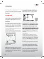
Turn it back on
User Guide
TI 1000 HC
READY
5.1CH
Stereo System
Coax-in
Optical
Please read this user manual carefully before using your TI 1000 HC and retain for future reference.
Turn it back on
CONTENTS
IMPORTANT SAFETY INSTRUCTIONS . . . . . . . . . . . . . . . . . . . . . . . . . . . . . . . . . . . . . . . . . . . . . 3 - 5
INCLUDED IN THE BOX . . . . . . . . . . . . . . . . . . . . . . . . . . . . . . . . . . . . . . . . . . . . . . . . . . . . . . . . 6
REMOTE CONTROL / REMOTE CONTROL INFORMATION . . . . . . . . . . . . . . . . . . . . . . . . . . . . 7 - 8
LOUDSPEAKER POSITIONING . . . . . . . . . . . . . . . . . . . . . . . . . . . . . . . . . . . . . . . . . . . . . . . . . . 9
FRONT PANEL INFORMATION . . . . . . . . . . . . . . . . . . . . . . . . . . . . . . . . . . . . . . . . . . . . . . . . . . . 10 - 11
REAR PANEL INFORMATION . . . . . . . . . . . . . . . . . . . . . . . . . . . . . . . . . . . . . . . . . . . . . . . . . . . . 12
CONNECTIONS . . . . . . . . . . . . . . . . . . . . . . . . . . . . . . . . . . . . . . . . . . . . . . . . . . . . . . . . . . . . . . 13 - 16
BASIC OPERATIONS . . . . . . . . . . . . . . . . . . . . . . . . . . . . . . . . . . . . . . . . . . . . . . . . . . . . . . . . . . 17 - 18
RADIO DATA SYSTEM . . . . . . . . . . . . . . . . . . . . . . . . . . . . . . . . . . . . . . . . . . . . . . . . . . . . . . . . . 19
OSD MENU . . . . . . . . . . . . . . . . . . . . . . . . . . . . . . . . . . . . . . . . . . . . . . . . . . . . . . . . . . . . . . . . . 20 - 29
BLUETOOTH . . . . . . . . . . . . . . . . . . . . . . . . . . . . . . . . . . . . . . . . . . . . . . . . . . . . . . . . . . . . . . . . . 30
TROUBLESHOOTING . . . . . . . . . . . . . . . . . . . . . . . . . . . . . . . . . . . . . . . . . . . . . . . . . . . . . . . . . . 31
SPECIFICATIONS . . . . . . . . . . . . . . . . . . . . . . . . . . . . . . . . . . . . . . . . . . . . . . . . . . . . . . . . . . . . . 32
Manufactured under license from Dolby Laboratories. “Dolby” and the double-D symbol are trademarks of Dolby
Laboratories.
Manufactured under license under U.S. Patent #’s: 5,451,942; 5,956,674; 5,974,380; 5,978,762; 6,226,616;
6,487,535; 7,212,872; 7,333,929; 7,392,195; 7,272,567 & other U.S. and worldwide patents issued & pending. DTS
is a registered trademark and the DTS logos, Symbol, DTS-HD and DTS-HD Master Audio are trademarks of
DTS, Inc. © 1996-2009 DTS, Inc. All Rights Reserved.
“HDMI”
Licensing LLC.
Before Connecting
rst to make all the connections to your speakers and source
equipment. Then set the unit up via its On-Screen Display (OSD) as there are various settings and adjustments
that need to be made before the TI1000 HC can be used.
However before you actually decide which connections to make or perform any adjustments it is
rst, starting on page 20.
A lot of explanation is included that will help you to choose the right connection types for both your sources and
TV.
2
Turn it back on
SAFETY
Safety precautions
A triangle with a
lighting symbol draws
the user’s attention to
“dangerous voltage”
without insulation in the cabinet,
which may be high enough to
entail a risk of an electric shock.
A triangle with an exclamation mark draws
the user’s attention to
important instructions
for use and maintenance in the accompanying manual, which should
be studied and adhered to.
Warning:
ed technicians are allowed to carry out repair and service of this
system.
If the plug of the power cord needs to be replaced. It is important that the replacement is identical to the plug that
needs to be replaced, or that the new plug has been recommended by the manufacturer.
Caution:
To avoid electric shock, it is important to insert the plug correctly into the wall outlet.
Important safety instructions
Warning:
It is important that you read and observe both the instructions in this manual and the instruction on the unit.
Keep this manual for safe future reference. This unit was designed and manufactured with a view to providing
built into this unit will protect the user if the procedures below are observed in connection with installation, use
and repair. This unit is fully electronic and contains no parts that can be repaired by the user.
ed technicians are allowed to repair the unit.
Read the manual
Heat
After unpacking the unit, please read the manual carefully and observe all the instructions given.
Do not place the unit near sources of heat such as
radiators, ovens or other units that produce heat.
Water and moisture.
The unit must not be placed close to water, such
as bathtub, wash basin, kitchen sink or washing
machine, in a damp cellar or close to a swimming
pool, etc.
Power supply
Only the power supply indicated on the rating plate
must be used for this unit. If you are not sure which
power supply you have, please contact your local
dealer.
Cleaning
Earthing or polarisation
If the plug cannot be inserted properly into the
t, the unit must not be
used in your country.
Ventilation
The cabinet is provided with slots and openings to
ensure ventilation and reliable operation and to protect
the unit against overheating. Do not block or cover
these openings. The openings must never be blocked,
for instance by placing the unit on a bed, a sofa, a
carpet or similar surface.
3
Unplug the unit before cleaning. Do not use liquid detergents and aerosol cleaning agents. Use a dry cloth.
Power cords
Wiring must be organised to prevent people from stepping on the cables and to avoid pinching by objects
placed on or beside them. Take special care around
sockets and plug boxes and where the power cords
leave the unit.
Lightning
Unplug the unit for additional protection during storms
or when the unit is not used for prolonged periods.
This will prevent damage to the unit from lightning and
power surges.
Turn it back on
SAFETY
Important safety instructions
Penetration of objects and liquid
Never push any foreign objects through the openings into the unit, as they may touch dangerous voltage points
or short-circuit parts and cause fire or an electric shock. Do not spill liquid onto the unit.
Accessories
Do not place the unit on unstable surfaces such as a trolley, stand, tripod, shelf or table. The
unit may fall and cause serious injury to persons or damage to the unit. Use only trolley, stand,
tripod, shelf or table that is very stable or provided with the unit. The unit must be installed in
accordance with the manufacturer’s instructions and by means of installation equipment recommended by the manufacturer. If the unit is placed on a trolley, the trolley must be moved very
carefully. Sudden stops, unnecessary force and uneven surfaces may cause the trolley to turn
over.
Loads
Do not place heavy loads on the unit and do not step on it. The load may fall and cause serious injury to persons
or damage to the unit.
Damage
Unplug the unit and contact qualified technicians in the following cases:
A. If the power cord or the plug is damaged.
B. If liquid has been spilled on the unit or objects have
fallen into the unit.
C. If the unit has been exposed to liquid or moisture.
D. If the unit does not work properly after adhering to the instructions in the operation manual. Only the settings
described in the operation manual must be made as incorrect setting may result in damage and often will
make it difficult for a qualified technician to make the unit work properly again.
E. If the unit has been dropped or damaged in any other way.
F. When the operation of the unit changes drastically, the unit requires service.
Service
Do not attempt to carry out any service work by yourself. By opening or removing the cover, you will be exposed
to dangerous voltage or other hazards. Any service work should be carried out by qualified technicians.
Recycling
If at any time in the future you need to dispose of this product please note that waste electrical
products should not be disposed of with household waste. Please recycle where facilities exist.
Check with your Local Authority or retailer for recycling advice.
Approval
This product complies with European Low Voltage and Electromagnetic Compatibility Directives
when used and installed according to this instruction manual.
4
Turn it back on
SAFETY
Important safety instructions
Overloading
Do not overload wall outlets or extension cords as this can result in the risk of fire or
electric shock. Overloaded AC outlets, extension cords, frayed power cables, damaged
or cracked wire insulation, and broken plugs are dangerous. They may result in electric
shock or fire hazard. Periodically examine the power cable - if its appearance indicates
damage or deteriorated receptacles have it replaced by your service technician.
Outdoor antenna grounding
ANTENNA
LEAD IN
WIRE
If an outside antenna or cable system is connected
to the product, be sure the antenna or cable system
is grounded so as to provide some protection against
voltage surges and built-up static charges. The example below is for reference only. Correct grounding
should always be installed by an electrician.
Conditions requireing service
GROUND
CLAMP
ANTENNA
DISCHARGE UNIT
(NEC SECTION 810-21)
ELECTRIC
SERVICE
EQUIPMENT
GROUNDING CONDUCTORS
(NEC SECTION 810-21)
Unplug this product from the wall outlet and refer
GROUND CLAMPS
servicing to qualified service personnel under the
POWER SERVICE GROUNDING
ELECTRODE SYSTEM
following conditions:
(NEC ART 250.PART H)
A. If the unit exhibits sudden unusual operation or
unusual display characteristics.
B. If liquid has been spilled, or objects have fallen into the product.
C. If the product has been exposed to rain or water.
D. If the product does not operate normally by following the operation instructions, adjusting only those controls
that are covered by the operation instructions. (NOTE: improper adjustment of other controls may result in
damage and will often require extensive work by a qualified technician to restore the product to its normal
operation).
E. If the product has been dropped or damaged in any way.
F. If the product exhibits a distinct change in performance.
Lightning
Unplug it from the wall outlet and disconnect the antenna or cable system. This will prevent damage to the product due to lightning and power line surges.
Heat dispersion
Leave at least 10 cm of space between the top, back and sides of the unit
and the wall or other components for proper ventilation.
Plug fitting instructions (UK only)
The cord supplied with this appliance is factory-fited with a UK mains plug
fited with a 5-amp fuse inside. If it is necessary to change the fuse, it is important that a 5-amp fuse is used. If the plug needs to be changed because
it is not suitable for your socket, or becomes damaged, it should be cut off
and an appropriate plug fited following the wiring instructions below. The plug
must then be disposed of safely, as insertion into a mains socket is likely to
cause an electrical hazard. Should it be necessary to fita 3-pin BS mains
plug to the power cord, the wires should be fited as shown in this diagram.
The colours of the wires in the mains lead of this appliance may not correspond with the coloured markings
identifying the terminals in your plug. Connect them as follows: The wire which is coloured BLUE must be connected to the terminal which is marked with the letter ‘N’ or coloured BLACK. The wire which is coloured BROWN
must be connected to the terminal which is marked with the letter ‘L’ or coloured RED. The wire which is coloured
GREEN/YELLOW must be connected to the terminal which is marked with the letter ‘E’ or coloured GREEN.
If a standard 13-amp (BS 1363) plug is used, a 5-amp fuse must be fited or, if any other type of plug is used, a
5-amp fuse must be fited, either in the plug or adaptor, or on the distribution board.
5
Turn it back on
INCLUDED IN THE BOX
Accessories
Included with the TI1000 HC AV Receiver are the following accessories:
1 x User Manual
1 x TI1000 Receiver
1 x Remote Control
1 x FM Antenna
1 x Main Plugs
Turn it back on
User Guide
TI 1000 HC
READY
5.1CH
Stereo System
Coax-in
Optical
Please read this user manual carefully before using your TI 1000 HC and retain for future reference.
Battery for remote control
1 x Set up microphone
Please save your packaging as you will need this in the event of warranty/service repair or support. We are
unable to carry out warranty/service if you are unable to package it correctly. The safest way to package your
item in the event of warranty/service repair is in it’s original box/packaging.
6
REMOTE CONTROL
Turn it back on
Connecting to the mains
By using the provided remote control, the receiver can be controlled from your listening position. To use the
remote control, point it at the REMOTE SENSOR window of the receiver.
Notes:
Even if the remote control is operated within the effective range, remote control operation may be impossible if
there are any obstacles between the unit and the remote control.
If the remote control is operated near other appliance which generate infrared rays, or if other remote control
devices using infrared rays are used near the unit, it may operate incorrectly.
The power is turned on/off (standby) by pressing the POWER button on the remote control in standby mode.
-
Precautions concerning batteries:
Be sure to insert the batteries with correct positive (+) and negative (-) polarities.
Use batteries of the same type. Never use different types of batteries together.
Rechargeable and non-rechargeable batteries can be used. Refer to the precautions on their labels.
When the remote control is not to be used for a long time (more than a month), remove the batteries from the
remote control to prevent them from leaking. If they leak, wipe away the liquid inside the battery compartment
and replace the batteries with new ones.
Do not heat or disassemble batteries and never dispose of old batteries by throwing them in a fire.
-
REMOTE CONTROL OPERATION RANGE
Use the remote control within a range of about 7 meters (23 feet) and the angles of up to 30 degrees aiming at
the remote sensor.
Battery installation
1. Remove the battery compartment cover.
2. Insert two “AAA” dry batteries. Make sure that the batteries are inserted with
their positive “+” and negative “-” poles positioned correctly.
3. Close the cover until it clicks.
If the distance required between the remote control and main unit decreases, the
batteries are exhausted. In this case, replace the batteries with new one.
7
Turn it back on
1. Power - Push this button to turn the unit into standby
mode, push it again to turn off the unit.
2. APS - In tuner mode, press this button to allocate and
memorize radio station automatically.
3. PTY search (this button is no function in this model) - Press to search by program type when in Tuner
mode. Refer to the “Operating instructions” section of
this manual for more information.
4. Tuner - Press to select the TUNER
5. ST/Mono - Press this button to alternate between
Stereo and Mono mode when listen to FM broadcast.
6. 7. Tuning (+/-) - Tunes frequency up/down.
8. Memory - Press it to store the broadcast station as
a preset.
9. Display - Press this button to display the state of input
source. When listening to the FM broadcasting with
RDS, press this button to show PS, PTY, RT and RT.
10. On-Screen Display (OSD) - Press to turn on and off
the on-screen setup menus for display on your monitor/screen/TV.
11. SPK setup - Press this button to select the desired
setting speaker, then press the “up/down“ buttons to
setup the speaker configuration.
12. LFE Trim - The LFE level can be adjusted within the
range of -10 to 0dB. In general, we recommend LFE
level to be adjusted to 0dB. (However, the recommend
LFE level for some early DTS software is -10dB.) If
the recommended levels seem too high, lower setting
as necessary.
13. Bass/Treble - Press this button for Bass/Treble adjustment and then press the +/- key to adjust the level.
14. CH SEL(this button is no function in this model)
- Select channels by pushing this button, then use
volume key to balance speakers
15. 16. Volume (+/-) - Press these buttons to decrease or
increase the volume.
17. Cursor Buttons - You can use these buttons to select
the option when in the OSD setup menu. You can use
the up and down buttons to select the stations when
in TUNER mode.
18. Enter - Used in OSD setup menu.
19. 20.CH SEL - When the button 14 is pressed, you can
press this two buttons to adjust the level.
21. Sub Vol
22.BD/DVD - Press to select the BD/DVD source equipment for output through this unit.
23.Video 1 - Press to select the source connected to
Video 1 for output.
24.Delay - Press this button to select the desired setting
speaker, then press the “up/down“ buttons to setup
the speaker delay time.
25.Video 2/3 - Press to select the source connected to
Video 2/3 for output.
26.Aux - Press to select the source equipment connected to AUX for output through this unit.
27. Line-In - Press to select the source connected to
Line-In for output.
28.Mute - Mutes the audio on the AV Receiver. Press
again to cancel mute.
REMOTE CONTROL
29.DTS/Dolby When playing
5.1CH source,
and while you
are enjoying
Stereo, push
this button
to playback
source in DTS/
Dolby Digital.
30.Dolby PLIIx
31. Surround Press to select
between various Pro Logic
II, DTS Neo:6
effects for
matrix encoded
analogue or
digital material or for postprocessing DD/
DTS material
(Note: TI 1000
HC is unable
to auto-detect
this kind of
source material
as it does not
include embedded encoding type flags (so manual
selection is required). Also selects various DSP
created surround sound modes for uncoded stereo
sources.
32.Audio In - Press to select analog inputs, digital inputs
and HDMI decoding for the currently selected source.
33.Sub On/Off - Push this button to turn on or off the
subwoofer output.
34.Stereo - When in the Stereo mode, only front left and
front right speakers are working. When in the Stereo
and Sub mode, only front left and front right speakers
and woofer are working.
35.Stereo Direct - Press to listen directly to the analogue
inputs for the current source with no analogue to
digital or DSP processing for highest possible stereo
sound quality.
36.Dynamic - Press this button repeatedly to reach the
desired dynamic compression range (Dolby Digital or
DTS modes only).
37. |ŻŻ/ŻŻ - Press this button to skip back a track./
Fast motion reverse playback.
38. Ź/||- Press this button to play or pause playback.
39.ŹŹ/ŹŹ| - Press this button to skip forward a track./
Fast motion forward playback.
40.Bluetooth - Press this button to activate Bluetooth
connection.
Note: You can use the 19, 20 buttons to select the
options when any of the “SPK SETUP” or“LEF
TRIM”or“CH SEL”or“DELAY” is pressed.
8
Turn it back on
LOUDSPEAKER POSITIONING
Standard speaker setup for surround sound
1
3
2
4
5
8
6
1. TV or Screen
4. Center speaker
7. Surround Right Speaker
7
2. Front Left Speaker
5. Front Right Speaker
8. Listening Position
3. Subwoofer
6. Surround Left Speaker
Standard speaker setup for surround sound
1. Front Right and Left speakers - These are the main speakers providing the front stereo effect of the sound
image.
2. Center speaker - Produces a rich sound image by serving as a sound source for the front right and left speakers and enhancing the sonic movement.
3. Surround Right and Left speakers - Adds three-dimensional sonic movement and produces environmental
sound associated with the background and effect sound for each scene.
4. Subwoofer - Produces powerful and heavy bass.
Speaker placement
Ideal speaker placement varies depending on the size of your room and the wall coverings. Here, only typical
examples of speaker placement and recommendations are shown.
Important points regarding speaker placement
Front Right and Left speakers and Center speaker
Place these three speakers all at the same height.
Place each speaker so that it is aimed at the location of the listener’s ears when at the listening position.
Place left and right speakers at the same distance from the listening position.
Subwoofer
Ideally a subwoofer should always be located in front of the listening position between the Front Left and Right
speakers. Since all rooms vary, experiment with the placement of your subwoofer for the best overall sound image (placing a subwoofer in the corner of a room often helps to disperse the sound).
Surround Left and Right Speakers
Place these two speakers all at the same height.
Place each speaker so that it is aimed at the location of the listener’s ears when at the listening position.
Place left and right speakers at the same distance from the listening position.
9
Turn it back on
FRONT PANEL CONTROLS
1. Display - Displays the status of the unit.
2. Volume - Use to increase/decrease the level of the sound from the output of the TI1000 HC.
3. Tuner - Press to select the tuner.
4. BD/DVD - Press to select the source connected to the BD/DVD input.
5. Video1/Video2 - Press to select the source connected to the Video1/Video2 input.
6. Aux/Rec - Press to select the source connected to the Aux input.
7. Line In - Press to select the source connected to the Line in input.
8. Stereo Direct - Press to listen directly to the analogue inputs for the current source with no analogue to digital
or DSP processing for highest possible stereo sound quality.
9. Bluetooth - Press to activate bluetooth function.
10. Power Standby/On - Push this button to turn on the unit, push it again to turn off the unit.
11. Line In - Use for Line-in source equipment connection.
12. Phones - Use for stereo headphones connection.
10
FRONT PANEL DISPLAY
Turn it back on
1. HDMI inputs - Indicates the current HDMI source input.
2. M- & PCM - Indicates the unit is receiving two channel or multi-channel PCM.
3. Surround decoding mode indicators (PCM, Dolby Digital, DTS etc) - Shows the current decoding mode,
Dolby Digital, DTS etc. In conjunction with the Output Channel indicator, these give full details of the current
processing mode.
4. Main information display - Shows the current source selected, also the surround mode and station name/
frequency when in tuner mode etc.
5. Output channel indicators - Shows the currently active channels depending on decoding mode and source
material. Channel icons lit indicate channels in the source material. Icons with a box around them indicate
channels with output by the unit.
Display examples
Indicates a 5.1 DTS master audio source being played back. The lit LFE indicates a low frequency effects channel is present in the source material. When this icon isn’t boxed it indicates the LFE channel is not being sent to
a subwoofer but will be mixed into the front left and right instead.
Indicates a 2.1 output created in the digital domain from analogue input material.
11
Turn it back on
REAR PANEL CONNECTIONS
1. Main Power Lead - Once you have completed all connections, plug the AC power lead into an appropriate
mains socket. The AV receiver is now ready for use.
2. Speaker Terminals (8Ω) - Connect to loudspeakers.
3. Sub Out - Connect to subwoofer.
4. Aux/Rec In - Connect to the line output of an external player.
5. Rec Out - Connect to the line input terminals on the REC DECK.
6. Composite Video and Analog Inputs - Video1, Video2 and BD/DVD.
7. Component Inputs and Outputs - Video1 and BD/DVD.
8. Digital Inputs - S/P DIF or Toslink digital inputs for each source.
You can choose to use a different type for each source but do not connect both at the same time for the
same source.
9. Update - For dealer use only.
10. HDMI In/Out
nition Multimedia Interface) connections carry digital audio and digital video.
The HDMI inputs are for connecting components with HDMI outputs, such as DVD players.
The HDMI outputs are for connecting a TV or projector with HDMI input.
11. Bluetooth
12. FM Antenna - All tuner antenna connections are made here. Refer to the ‘“Antenna Connections” section of
this manual for more information.
12
Turn it back on
CONNECTIONS
Loudspeaker Connections
Caution:
To avoid damaging the speakers with a sudden high-level signal, be sure to switch the power off before connecting the speakers.
t Check the impedance of your speakers.
t
t
er’s red speaker terminals are the + (positive) terminals and the black terminals are the – (negative) terminals.
The + side of the speaker cable is marked to make it distinguishable from the – side of the cable. Connect this
marked side to the red + terminals and the unmarked side is the black terminal.
Prepare the speaker cords for connection by stripping off approximately 10 mm or less (no more as this could
cause a short-circuit) of the outer insulation. Twist the wires tightly together so that they are not straggly.
1
2
3
1. Unscrew the knob.
2. Insert the speaker cable.
3. Tighten the knob and secure the cable.
Note: The front left speaker and front right speaker connections are made via loudspeaker cable, while the active subwoofer is connected via a standard RCA phono cable.
13
Turn it back on
CONNECTIONS
Analogue Audio Connections
Note: Do not plug in the mains power lead or turn on the unit until all connections have been made.
Connect to source equipment using phono cables (stereo 2RCA-2RCA).
Digital Audio Connections
Two types of digital audio connections can be made to this unit, coaxial (S/P DIF) and optical (Toslink).
Either type can be used for a source as the TI1000 HC automatically uses the active one.
Note: Only one connection type should be used per source.
Analogue Video Connections
There are two types of video connections can be made on TI1000 HC Composite and Component. For best
picture quality we recommend making Component video connections, then in declining order of quality and then
Composite video connections.
14
Turn it back on
CONNECTIONS
HDMI Input Connections
nition Multi-Media Interface) is an all digital connection that can carry both audio and video in
and high resolution audio make this the best connection type to use. The 4 HDMI inputs can be assigned to the
BD/DVD, Video 1, Video 2, CD/Aux/TV, Tape/MD/CDR.
HDMI Cable
Camcorders
HDMI Cable
Games Consoles
HDMI Cable
DVD/Blu-ray player with HDMI output
HDMI Cable
HDMI set-top box (Sky HD)
Video Output Connection (HMDI)
Connection to the TV is by HDMI. The TI1000 HC converts incoming analogue video to HDMI and scales it for
best picture quality.
HDMI cable
Note: The HDMI output supports Audio Return Channel (ARC) from TV’s with this feature see page 31.
15
Turn it back on
CONNECTIONS
Front Input Connections
For private listening, you can connect a pair of stereo headphone (1/4-inch phone plug) to the AV receiver’s
PHONES jack.
FM aerial
Aerial Connections
FM aerial
Connect an aerial to the FM 75 ohm socket (a simple wire aerial is
supplied for temporary use). Extend the lead and move the aerial
around until you get the best reception. For continued use, we
strongly recommended using a 75 ohm outdoor FM aerial.
OR
FM external aerial
A N T EN N A
FM
75
16
Turn it back on
BASIC OPERATIONS
BASIC OPERATION 1
were monaural (the surround left and right channels
were the same) with previous Dolby Pro Logic, but
Dolby Pro Logic II they are played as stereo signals.
Various parameters can be set according to the type
of source and the contents, so it is possible to achieve
optimum decoding.
SURROUND MODE
1. Press the Power On/Off button on the front panel to
switch on the unit.
2. Select the desired source by pushing the corresponding button.
-
TUNER (FREQUENCY)
BD/DVD (ANA, COAX, HDMI)
VIDEO 1 (ANA, COAX, HDMI)
VIDEO 2 (ANA, OPT, HDMI)
AUX/ REC (ANA, OPT)
LINE IN
STEREO DIRECT
BLUETOOTH
If
appears on the display: A digital input
source (OPT or COAX or HDMI) has been selected, and the source is connected successfully.
If “UNLOCK” appeared for 5 seconds on the
display: The source is not connected properly or the
source is not switched on.
In that case, connect and switch the source on, or
select ANALOG by pressing the INPUT MODE button.
Play the source, and gradually turn up the volume to
the required level with the MASTER VOLUME control.
BASIC OPERATION 2
STEREO
With the unit in the STEREO mode, only Front Left,
Front Right Speaker and Woofer will have output.
Dolby Pro Logic II
Dolby Pro Logic II is a new multi-channel playback format developed by Dolby Laboratories using feedback
logic steering technology and offering improvements
over conventional Dolby Pro Logic circuits.
Dolby Pro Logic II can be used to decode not only
sources recorded in Dolby Surround but also regular
center, surround left and surround right) to achieve
surround sound.
Whereas with conventional Dolby Pro Logic the surround channel playback frequency band was limited,
Dolby Pro Logic II offers a wider band range (20 Hz to
20 kHz or greater). In addition, the surround channels
17
eld
with a “three dimensional” feel, giving the sense of
distance, movement and relative position and creating
a surprisingly real and powerful sense of presence
when playing movie software in AV rooms.
Press to select between various Pro Logic II, DTS
Neo: 6 effects for matrix encoded analogue or digital
material or for post-processing DD/DTS material
Note: TI 1000 HC is unable to auto-detect this kind
of source material as it does not include embedded
ags so manual selection is required.
Also selects various DSP created surround sound
modes for uncoded stereo sources.
RESET
When this unit is ON, press down TUNER and
BLUETOOTH buttons on the front panel at the
same time for more than 3 seconds to reset the whole
system (including memories).
PHONES jack
For private listening, insert optional (not included)
headphones (1/4-inch plug) into the PHONES jack,
and then the center and surround speaker will be cut
automatically.
Note: When the headphone is used, the output will
down mix to STEREO automatically.
BASS/TREBLE Control
BASS control is used to adjust the level of the low
frequency sound range.
TREBLE control is used to adjust the level of high
frequency sound range.
Press one of them on the remote control and then
press Vol+/- key to adjust the level of them.
Turn it back on
BASIC OPERATIONS
Radio Operations
Automatic Tuning
1. Press the Power On/Off button on the front panel to
turn this unit on.
2. Press the Tuner button on the front panel or on the
remote control.
3. Press the “APS” button on remote control to
activate automatic selection. (Default mode is
Manual selection). ( Note: SEARCHING appears
on the display).
4. Press TUNING + and TUNING - to select the
station you want to listen to. When a station is
tuned in, the tuning process will stop automatically.
(Automatic selection).
5. Press TUNING + or TUNING - again to select
another channel.
Manual Memory Presetting
1. Press the Tuner button on the front panel or on the
remote control.
2. Press the TUNING + or TUNING - buttons to select
a frequency channel you want to preset.
3. Press the MEMORY
4. The station number will be displayed on the screen.
5. Press the MEMORY
more stations, repeat steps 2 to 6.
Manual Tuning
It is for selecting stations, which cannot be tuned
automatically. (Manual selection).
To tune a channel manually:
Skip step 3 in the above procedures. Each time the
TUNING+ or TUNING- button is pressed momentarily
step: FM: 50 kHz steps; MW: 9 kHz steps.
Two FM modes available:
Press STEREO or MONO button on remote control to
select Stereo mode or Mono mode.
Stereo
FM stereo broadcasts are received in stereo and the
“ST ” indicator lights on the display.
Mono
To compensate for weak FM stereo reception, select
this mode. Reception will now be forced monaural,
reducing unwanted noise.
If DISPLAY button is pressed, the details of incoming
source will be displayed.
Preset Tuning
This facility is used to store FM broadcasting from
channel 1 to 20 respectively.
How to select preset stations
Press the “ ” “
” on remote
control to select a preset channel during the tuner
mode.
18
Turn it back on
RADIO DATA SYSTEM
RADIO DATA SYSTEM (RDS)
PTY SEARCH (Program Type Search)
RDS is a method for the transmission of additional
information from local Radio Stations. It can only be
operated in FM mode. For example, name of the station broadcasting, name of the program or the type of
program will be shown on the multi-function display.
1. Press the “PTY” on remote control,
ash on the display.
“PTY SEL”
2. Press TUNING + /- to choose the program type, for
example, NEWS, SPORT, etc...
3. Press “PTY” again once you choose the
program type.
4. When the type of program tuned in, it will stop
searching, otherwise, “NO FOUND” will appear.
It functions only when the local broadcasting stations
have the RDS transmission and the signal is strong
enough.
Press “DISPLAY” on remote control, there are functions for PS, PTY, CT and RT.
a) PS (Program Service Name)
Press “DISPLAY” on remote control until the current
station name appears.
Note: “NO PS” will be shown if the signal from local
radio station is not strong enough or no such service.
b) PTY (Program Type)
Press ”DISPLAY” on remote control until the current
name type of the program appears.
Note: “NO PTY” will be shown if the signal from local
radio station is not strong enough or no such service.
c) CT (Clock - Time)
Press “DISPLAY” on remote control until the current
time from Radio Station appears. e.g. 15:30.
Note:
1. The Clock - Time will be only transmitted from local radio station once a minute, so you need to wait
for less than 1 minute to show the result.
2. “NO CT” will be shown if the signal from local radio station is not strong enough or no such service.
d) RT (Radiotext)
Press “DISPLAY” on remote control until some Text
messages appears.
Note: “NO RT” will be shown if the signal from local
radio station is not strong enough or no such service.
19
APS (Auto Program Search)
Pressing the “APS” on remote control, it will search
the available stations.The searched stations will be
memorised in the respective band memory up to
maximum 20 memories.
Note: Weak station may also be stored in memory, so
manual memory presetting may be needed in order to
have better reception.
Turn it back on
OSD MENU
Setup
The setup of TI1000 HC is a reasonably simple 4
stage process. The speaker setup process (stage 2.)
can either be performed manually or via Microphone
procedure.
The procedure is as follows:
guration.
2. Speaker setup (Speaker delay and Level calibration).
3. Assigning any HDMI sources.
4. Source setup (Audio type and Video type for each
source).
Follow the on-screen instructions and press ‘Enter’ on
the remote control when ready to start the Auto Setup
function.
Once activated the OSD will display the message below and the word ‘AUTOSETUP’ will also be displayed
guration
Auto speaker set up using microphone
TI 1000 HC includes our simple automatic speaker
setup system. The system performs two sets of tests
whether they are wired correctly and in phase, then
automatically measuring and adjusting the speaker
delay timings (i.e. distance setting) and levels.
Before activating this feature the ‘Decode Mode’ of
TI 1000 HC and Large/Small/None status of each
speaker must be set correctly as explained on page
22.
A series of test signals will now be output from all
of the connected speaker terminals of TI 1000 HC
(including the Subwoofer output).
the one below reporting which speakers were found
and any that appear out of phase.
This is important as the unit will only look for and
check the speakers you have told it you have.
supplied microphone to the line in input on the front
panel and place it at your normal listening position in
the room.
Press the OSD button on the remote control to access
the OSD and then select the Speaker Setup Menu.
Now select the option ‘Auto Setup’. This will access
the ‘Auto Setup Menu’ as opposite.
If any speakers appear unconnected or out of phase
carefully check the connections on the speaker and
the back of the unit. Also check any bi-wiring links that
might be present on the speaker. For any out of phase
speakers check that the relevant + (positive) terminal
of TI 1000 HC goes to the + (positive) terminal of that
speaker and similarly the - (negative) terminal of TI
1000 HC goes to the - (negative) terminal the speaker
for that channel.
20
Turn it back on
OSD MENU
If necessary press the OSD button to perform a retest
or press Enter to start the second part of the autosetup procedure as below.
Again a series of test signals will now be output from
all of the connected speaker terminals and Subwoofer.
TI 1000 HC uses these to measure the levels and
distances (and hence introduce the correct delays) appropriate to your speakers and room characteristics.
connection and any other external issues that could
have affected the tests such as noise in the room etc.
Note: Like all such systems this has some limitations.
Speakers that exhibit very strong phase angles or
deliberately wire some drive units out of phase can
of course appear to the system as an out of phase
speaker when correctly connected. If a speaker is
reported as out of phase but is correctly wired please
consult the speakers manufacturer in case this is the
case.
Similarly bi-polar speakers which radiate in more
than one direction can make it difficult to measure the
distance and sometimes level accurately as you might
expect.
In all cases it is always advisable to manually check
the settings system has made for a “reality check” to
ensure there are no obvious errors.
When the auto setup of TI 1000 HC is completed
successfully, TI 1000 HC will return to the Speaker
Setup Menu.
The Speaker Distance and Level Calibration settings
for each speaker will have been updated.
It is of course now possible to go into the Speaker Delay and Level Calibration menus if you want to manually check/adjust the settings made by the system. It is
always advisable to check them as no system can be
totally foolproof.
To exit the auto setup menu of TI 1000 HC continue
to press the OSD button on the remote control to exit
all menus or until “OSD” is no longer displayed on the
front panel. You can now unplug the microphone and
put it away for future use.
Note: If the auto setup of TI 1000 HC is unsuccessful
for some reason a ‘Fail’ message will appear on the
OSD. Included in this message will be details of the
speaker channel or channels which have not been
successfully adjusted. If this is the case, please again
check that the speaker or speakers detailed in the
OSD as ‘failed’ are connected correctly and have not
been wired out of phase. Also check the microphone
21
Manual speaker set up
First tell the unit what kind of speaker package you
have. The options are 5.1 as shown below. TI 1000
HC can support up to a 5.1 speaker setup which
means 5 speakers (Front Left, Front Right, Centre,
Surround Left, Surround Right) plus a mains powered
Subwoofer .
Refer to the diagrams on
the right for typical examples of 5.1, loudspeaker
setups. Always adjust the
speaker and listening positions until you are happy
with the sound. Please
refer to your loudspeaker
and subwoofer manuals for
more detailed positioning
information.
1
1
2
4
3
5.1
3
1. Front Left and Right speakers - For stereo and
multi-channel sound.
2. Centre speaker - For dialogue and centre sounds.
Ideally position at a similar height to the front
left and right speakers (above or below the TV/
monitor). Using a centre speaker from the same
manufacturer/range as used for the front left and
right speakers is advisable. This “timbre matching”
ow more naturally from
left to right without obvious transitions between the
speakers.
3. Surround Left and Right speakers - For ambient
and multi-channel sound. Floorstanding speakers
should be angled towards the listening position.
Bookshelf/standmount speakers should be wall
mounted or used with dedicated speaker stands,
Turn it back on
OSD MENU
positioned at or above ear height.
4. Subwoofer - For improving the bass in your
system, as well as reproducing dedicated LFE
(Low Frequency Effects) cinema effects when
playing Dolby Digital or DTS encoded discs. Your
subwoofer can often be placed almost anywhere in
the room as bass is less directional, but experimentation with positioning is recommended.
In each case the 5.1 in fact relates to the maximum
number of speakers that can be used, as the Centre,
Sub and Surround speakers can all be deleted if
required (although of course performance is reduced).
For example, if you choose not to use a Centre Channel speaker you can set this to ‘None’ in the settings
as shown later and TI 1000 HC will automatically
redirect the centre channel audio information into the
Left and Right Front channels, creating what is known
as a “Phantom Centre”.
Similarly, you might decide not to use a subwoofer
if your main Left and Right speakers are capable
of reproducing enough bass for a satisfying music/
movie experience. TI 1000 HC will then automatically
re-direct the bass from the Subwoofer/Low Frequency
Effect channel to the Left and Right Front Speakers.
Note: This setup is very important as TI 1000 HC
will also automatically use this information to select appropriate Dolby and DTS decoding modes
dependant not only on the source material but
also the speaker package it knows you have.
To tell the unit the type of package you have, turn
on the On-Screen Display via the remote button as
guration” menu
shown. Highlight the “
by using “
” and “
” on the remote then go to it
by pressing Enter:
Now move down and by highlighting each speaker in
turn and using the Left and Right arrows select from “
Large”, “Small” or “ None” for each speaker. “Large’ or
‘Small’ are used to describe each speaker in terms of
ect the
actual physical size of the speaker.
Large = Speakers with an extended low frequency
response of approximately 20-40Hz to 16-20kHz
oorstanders or high quality larger stand-mounted
speakers).
Small = Speakers with a less extended low frequency
response of approximately 80-100Hz to 16-20kHz
(small stand-mounted, bookshelf or satellite speakers).
Setting each speaker allows TI 1000 HC to perform
what is called Bass Management and to direct low
frequency bass from music and the Low frequency
effects channel of surround sound material to those
speakers best able to reproduce it. If you do not wish
to use any of the speakers, set its setting to “None”.
The Subwoofer output can also be set to On or Off. If
no sub is being used make sure this setting is set to
Off to allow TI 1000 HC to re-direct the bass information in this channel to other speakers.
Note: TI 1000 HC will force some speakers to certain
settings in some of the following circumstances!
The Front Left and Right speakers may be “Large” or
“Small” but never “None” as they are always required
for any type of music/movie reproduction.
Bass must always be reproduced by either the Front
Left and Right or Subwoofer channel (or both). Setting
the Front Left and Right to “Small” will result in the
Subwoofer automatically being set to “On”. Setting the
Subwoofer to “Off” will automatically result in the Front
Left and Right being set to “Large”.
Set the package as 5.1 by highlighting the Decode
Mode item and using the Left and Right arrows to
scroll through the options:
If the Front Left and Right cannot reproduce low
frequency bass a Subwoofer must be used. i.e. If the
Front Left and Right are set as “Small” the Sub must
be Set to “On”.
Also, setting the Front Left and Right as “Small” will
always set the other speakers as “Small” (and the Sub
22
Turn it back on
OSD MENU
to “On”). This is because LFE/ bass information should
not be redirected to the surround channels.
To store the setting simply come back out of the OSD
(pressing the OSD button always moves back one
menu item, and then exits and stores from the main
menu screen).
Go to the “Speaker Distance” and highlight each
speaker in turn. Set the distance to the nearest value
to that which you measured by using the Left and
Right arrows (the values do not need to be exact).
Press the OSD button to exit the menu.
2. Speaker setup
The following two sections can be performed by Microphone so you can if you wish jump straight to that
section. However, it is recommended that you do read
these sections to understand the reasons for these
settings and their implications.
Speaker delay
Because the speakers in a surround sound system are
usually different distances from the listener, TI 1000
HC incorporates the ability to apply a variable digital
delay to each of the channels, so that the sound from
each arrives at the same time at the listening position
for best surround-sound effect.
To set the delay times automatically, refer to the Auto
setup section of this manual.
To set the delay times manually, simply measure the
distances from the listening position to each speaker
as shown in the following diagram:
Note: In addition to the delays as set above Dolby
Pro Logic II/IIx playback also requires an extra 15
milliseconds delay to the surround channels only. This
and ensures that sound from the surrounds arrives
just after sound from the front reducing the audibility of sound leakage from the front to the surround
speakers. Because the relationship between the Dolby
extra to the surround channels), it is only necessary to
set the delay by measuring the distances as we have
described. TI 1000 HC will automatically provide the
appropriate extra delay whenever you switch to a Pro
Logic Mode.
Level calibration
1
1
TI 1000 HC allows level calibration to match the
acoustic level between different types/sizes or even
manufacturers of speaker that may be being used for
each channel. This is achieved by adjusting the relative level of each speaker. This can be done manually
through the ”Level Calibration” menu in the OSD or
automatically, see the following Auto setup section of
this manual.
2
4
3
1.
2.
3.
4.
5.1
3
Front Left and Right speakers
Centre speaker
Surround Left and Right speakers
Subwoofer
Note: No delay setting for the subwoofer is necessary.
Set the distances in the OSD Speaker Distance menu
to the nearest value in metres (1 foot = 0.3 metres).
The speed of sound is approx 340 metres per second,
TI 1000 HC thus introduces approx 3mS of delay per
metre of distance set..
23
The basic process for manual adjustment is to listen
to or measure with an SPL meter (more accurate and
recommended but not essential) the level of sound
produced by each speaker and set relative levels
for each speaker so that they all sound the same
loudness at the normal listening position. TI 1000 HC
incorporates a Test Signal Generator (broad-band
white noise) to facilitate this.
Set the unit to a normal listening level or half maximum volume approximately. Press the OSD button on
the remote control then select the ”Level Calibration”
menu. Now turn on the test signal by highlighting this
item and pressing the Left or Right arrows.
Turn it back on
OSD MENU
t The processing mode for that source.
TI 1000 HC remembers these settings individually
for every source input and automatically recalls
them as and when you change source input.
Remember if you wish to use HDMI for any sources
you must have assigned an HDMI input to them as per
previous section.
4. Audio connection type
A “rushing” or “hissy” sound should be heard, initially
through the Front Left Speaker.
You can now move up and down the channels using
Volume Up/Down on the remote control. Each time a
new channel is selected the test signal will be heard
through that channel. Compare the loudness of all
channels as heard at the listening position.
Now adjust the channels so they all sound the same
(in terms of loudness only, channels of different frequency responses can sound different in terms of the
“tone” of the sound i.e. more or less hissy).
Pick the channel that sounds most different and select
it to listen to the test signal. Now adjust the relative
level in dB (using Arrow left/right on the remote control) and continue comparing it to other channels until
it is of equal loudness. The level can be adjusted up
to + or - 10dB in 1dB steps. Repeat the process with
the next loudest channel etc. Once all channels sound
the same in terms of loudness, press the OSD button
again to save the settings and exit the menu.
Select the “Audio Input” menu. Highlight
each source in turn and select either analogue or
digital input types (use the Left and Right arrows).
Analogue inputs will require a stereo phono/RCA to
phono/RCA cable connection to TI 1000 HC. Digital
inputs will require either a 75ohm digital type phono/
RCA to phono/RCA co-axial cable (SPDIF) or an
bre cable (TOSLINK). TI 1000 HC will automatically use whichever is connected. Do not make
connections to both the Optical and Co-axial inputs
for a source.
Once you have set the audio types exit the OSD to
save.
This setting can also be changed at any time without
using the OSD by pressing the Audio Input Type button on the front panel or remote control, this will then
cycle between analogue or digital input types for the
currently selected source, as usual they will then be
remembered the next time you return to that source.
3. Source setup
The next step is to select each source input in turn on
TI 1000 HC and tell the unit:
t The type of audio connection you want to use for
that source (Analogue, Digital or HDMI input).
t The type of video connection you want to use for
that source (HDMI or CVBs, YPbPr ).
24
Turn it back on
OSD MENU
5. Tone/Sub/LFE Menu
Select the “Tone/Sub/LFE” menu
The Bass response can be adjusted +/- 10dB @
100Hz (shelving). The Treble response can be adjusted +/-10dB @ 10kHz (shelving).
TI 1000 HC incorporates a couple of advanced Bass
Management features. The overall Sub Level for DD/
DTS modes, PLII/x/Neo:6 modes and Stereo + Sub
mode can be set to different levels. This can be useful
if you prefer to have a high level of Sub operation
whilst watching movies but a lower level for music
playback. The three levels are simply adjusted by up
to +/-10dB in the OSD. The second feature is that the
way Bass Management is applied can be changed.
In normal operation (Bass Augment Off) if the Front
ltering
the Fronts and sending that bass to the Sub channel
(i.e. bass is removed from the Fronts and sent to the
ltering takes place and
no bass is sent from them to the Sub channel.
However with the Bass Augment function On and the
Front speakers set to ” Large”, bass from the Front Left
and Right is now sent to the Sub channel without any
ltering of the Front Left and Right taking place (i.e.
these channels remain full range). In other words, the
bass in the Sub channel is augmented by extra bass
from the Front Left and Right channels. If the Front
Left and Right are set ”Small”, Bass Augment has no
effect and operation is the same as for Bass Augment
Off.
Bass Augment can be On or Off separately for DD/
DTS or PLII/IIx/Neo:6 operation.
There is no Bass Augment function for Stereo + Sub
mode because in this mode if the Front speakers are
ltered.
25
Bass Augment can be a useful function with PLII
and Neo:6 material because these encoding types
do not include an LFE Channel. This would normally
mean that if all the speakers in your setup were set
to “ Large”, the subwoofer would in fact be inactive (as
no bass has been re-directed plus there is no LFE
channel). If it is desired to have the subwoofer running
with all Large Speakers and these encoding types,
enable Bass Augment for PLII/Neo 6 and then set the
Crossover points and levels by ear. A Sub channel will
now be created from the Front Left and Right channels
ltering them. As with all adjustments it is a
good idea to experiment to determine what works best
in your particular setup.
Note: These adjustments work in all digitally processed Stereo or Surround modes but not in Analogue
Stereo Direct or 5.1 Direct modes.
The LFE channel (for DD / DTS material) can also
be trimmed by up to 10dB in 1dB steps useful for
late night listening or other situations where it might
be desired to reduce the low frequency effect level
perhaps temporarily.
Remember the LFE is the Low Frequency Effects
channel encoded into the disc and is different to the
over all sub level which can include bass management
from the other speakers.
Bass/Treble adjustments can also be made from the
remote control without entering the OSD by pressing
the Bass/Treble button and then using the Vol Up/
Down buttons.
Sub trim adjustments can also be made from the
remote control without the OSD by holding down the
Sub On/Off button and using the Vol Up/Down buttons
whilst it is kept down.
Surround sound modes
TI 1000 HC supports several music and home-cinema
listening modes. The output TI 1000 HC can provide,
depends both on the source signal present, the
speaker setup selected and the decode mode selected. Before we describe how to operate TI 1000 HC,
below is a brief guide to the Surround Sound formats
that TI 1000 HC is compatible with for reference:
Dolby True HD
Dolby’s lossless audio technology developed primarily
for high capacity Blu-ray discs/players. Dolby True HD
delivers theoretically bit-for-bit sound identical to the
studio master by the use of 100% lossless encoding. Previous formats such as Dolby Digital 5.1 or EX
Turn it back on
have used lossy encoding where some data (that is
theoretically less audible) is always lost in the encoding process to reduce the storage capacity needed on
the disc. This is a new format that supports up to eight
(usually used as 5.1) full-range channels of 96kHz/24
bit audio or two channels of 192 kHz via Blu-ray discs
and is not backwards compatible with earlier schemes.
The format can either be transmitted as a (R)bit
stream! to TI 1000 HC for internal decoding (recommended) or can be decoded by some Blu-ray players
internally and sent to TI 1000 HC as multi-channel
PCM. In both cases an HDMI connection is required
to TI 1000 HC and a suitable Blu-ray player as Dolby
True HD is only ever transmitted over HDMI.
Dolby Digital Plus
A new encoding scheme based on the original Dolby
Digital CODEC, but with enhancements to improve
coding efficiency and improve audio quality. Dolby
Digital Plus supports 5.1 fully discrete channels
compared to Dolby Digitals 5.1 (or 5.1 in its EX variant
where the 6th channel is matrix encoded). These
Dolby Digital Plus bitstreams are not backward compatible with legacy Dolby Digital decoders but require
an AV Receiver developed to decode them (such
as TI 1000 HC) and an HDMI connection as Dolby
Digital Plus is currently only transmitted over HDMI. It
is however a requirement that any Dolby Digital Plus
enabled Blu-ray player must also be able transform
the Dolby Digital Plus into a backwards compatible
Dolby Digital 5.1 output for playback on legacy Dolby
Digital systems. TI 1000 HC is however fully compatible with Dolby Digital Plus.
DTS-HD Master Audio
A new lossless audio CODEC from DTS, rather than
being incompatible with earlier versions, DTS-HD
Master Audio is transmitted as an extension to a
normal DTS bitstream. A second embedded stream
is sent which contains the “difference” between the
original studio master and the lossy compressed DTS,
plus the two extra channels. DTS-HD Master Audio
enabled devices (such as TI 1000 HC) are able to use
this difference information to recreate a bit for bit lossless version of the original 5.1 data. Devices which do
not support the Master Audio extension simply decode
the original 5.1 DTS stream and ignore the Master
Audio extension providing backwards compatibility.
DTS-HD High Resolution Audio
Known also as DTS-HR an extension to the original
DTS audio format. DTS-HD High Resolution Audio
supports 5.1 fully discrete channels compared to
DTS’s 5.1 (or 5.1 in its DTS ES Matrix or DTS ES
Discrete variants). As with DTS-HD Master Audio a
OSD MENU
second embedded stream is sent which contains the
“difference” between the original studio master and the
lossy compressed DTS, plus the two extra channels,
however in this case the extra stream is also formed
by lossy compression. Effectively this is a 5.1 version
of DTS which can be decoded by devices (such as
TI 1000 HC) which are able to decode DTS-HD High
Resolution Audio. Devices which do not support the
High Resolution extension simply decode the original
5.1 DTS stream and ignore the High Resolution extension providing backwards compatibility.
Dolby Digital
Known also as DD (3/2) or DD 5.1, provides (up to)
5.1 output from suitable encoded Dolby Digital material, with 5 main channels (Front Left, Front Right,
Centre, Surround Left, Surround Right) and a Low
Frequency Effects Channel for the subwoofer, all
discretely encoded. Decoding Dolby Digital requires
a Dolby Digital encoded DVD disc and a digital connection from the souce equipment (Such as a DVD
player) to TI 1000 HC.
Note: Dolby Digital and DTS formats can sometimes carry less channels than their maximum such
as Dolby Digital (2/0) which means a Dolby Digital
encoded signal which is actually only carrying a two
channel stereo signal (other channels inactive).
DTS
Known also as DTS (3/2) or DTS 5.1, DTS provides
(up to) 5.1 output from suitable encoded DTS material, with 5 main channels (Front Left, Front Right,
Centre, Surround Left, Surround Right) and a Low
Frequency Effects Channel for the subwoofer, all
discretely encoded. Decoding DTS requires a suitably
encoded DTS disc and a digital connection from the
source equipment to TI 1000 HC.
Dolby Digital EX
Known also as DD (3/3) or DD 5.1, an enhanced form
of Dolby Digital. On top of the discretely encoded
5.1 channels DD EX provides an extra 6th channel
(Surround Back, giving 5.1) matrix encoded into the
rear surrounds for greater image depth and more solid
sound localisation behind the listener. DD EX requires
a DD EX encoded disc. DD EX is backwards compatible with DD 5.1 decoding. If DD EX is decoded as
normal DD the Surround Back signal will be present
in both Left and Right Rear Surrounds (forming a
phantom rear centre). It can also be decoded as 5.1
by sending the Surround Back decode to both the
Surround Back Left and Right speakers (forming two
mono Back Surrounds).
26
OSD MENU
DTS-ES Matrix
Known also as DTS (3/3) Matrix, an enhanced form
of DTS. On top of the discretely encoded 5.1 channels DTS ES also provides an extra 6th channel
(Surround Back giving 5.1), matrix encoded into the
rear surrounds for greater image depth and more
solid sound localisation behind the listener. DTS ES
requires a DTS ES encoded disc. DTS ES material is
backwards compatible with DTS 5.1 decoding. If DTS
ES is decoded as normal DTS the Surround Back
signal will be present in both Left and Right Rear Surrounds (forming a phantom rear centre). It can also be
decoded as 5.1 by sending the Surround Back decode
to the both the Surround Back Left and Right speakers
(forming two mono Back Surrounds).
DTS-ES Discrete
Another enhanced form of DTS, also known as
DTS (3/3) Discrete or DTS ES Discrete 5.1. DTS ES
Discrete also provides an extra channel (Surround
Back) for greater image depth and more solid sound
localisation behind the listener, however in this case
extra data is included in the bitstream so that all
channels are discretely encoded. The Surround Back
has greater separation from the other channels than
is possible with matrix encoded technologies. DTS-ES
Discrete requires a DTS-ES Discrete encoded disc.
DTS ES Discrete is backwards compatible with both
DTS 5.1 and DTS ES Matrix 6.1 decoding. If DTS
ES Discrete is decoded as normal DTS the Surround
Back signal will be present in both Left and Right Rear
Surrounds (forming a phantom rear centre). If DTS ES
Discrete is decoded with DTS ES Matrix the Surround
Back signal will be decoded separately (i.e. as 6.1) but
by a matrix process, which will give the same channel
separation as if the source disc were actually DTS ES
Matrix (but not as good as DTS EX Discrete).
It can also be decoded as 5.1 by sending the Surround Back decode to both the Surround Back Left
and Right speakers (forming two mono Back Surrounds).
Pro Logic II
The replacement for original ProLogic, Pro Logic II is a
technology where 5 channels (Front Left, Front Right,
Centre, Surround Left, Surround Right) are encoded
into a Stereo mix by an analogue matrix process.
Dolby Pro Logic II material can be played back by
normal Stereo equipment (as Stereo) or decoded into
5 channel surround-sound.
27
Turn it back on
Dolby Pro Logic II is compatible with the earlier 4
channel (Left, Centre, Right and mono Surround) Dolby Pro Logic system (which was the decoding counterpart to Dolby Surround encoding) as used widely on
Video tapes, TV broadcasts and earlier films.
Note: Pro Logic does not include a Low Frequency
Effects channel for the Subwoofer, but TI 1000 HC can
create a Subwoofer output (for 5.1) via Bass management. Refer to the (R)Tone/Sub/LFE configuration!
section in the “Operating instructions” part of this
manual.
DTS Neo:6
A DTS technology which is able to recreate 6 channel
(Left Front, Right Front, Centre, Left Surround, Right
Surround, Surround Back ) surround sound from suitable analogue matrix encoded stereo source material.
DTS Neo:6 material can be played back by normal
Stereo equipment (as Stereo) or decoded into 6 channel surround-sound.
Note: Neo:6 does not include a Low Frequency Effects channel for the Subwoofer, but TI 1000 HC can
create a Subwoofer output via Bass management.
Refer to the (R)Tone/Sub/LFE configuration! section in
the “Operating instructions” part of this manual.
DTS Neo:6 can also be decoded as 5.1 by sending
the Surround Back decode to both the Surround Back
Left and Right speakers (forming two mono Back
Surrounds).
DTS 96/24
A DTS technology that provides 5.1 channels of
96kHz / 24bit audio (along with video if required) on
DVD-Video and DVD-Audio (video zone) discs (when
suitably encoded in DTS 96/24). DVD players which
allow ‘DTS digital out’ pass the DTS 96/24 bitstream
over S/PDIF for decoding in TI 1000 HC.
DSP modes
These modes allow a surround-sound experience
from source material that has no encoding at all. The
surround sound effect is achieved by Digital Signal
Processing of the Analogue or Digital stereo source
used. Five modes are possible: Movie, Music, Room,
Theatre and Hall.
Stereo/Stereo + Sub
Only the Front Left and Front Right speakers (and
subwoofer if selected) have output in this mode. If an
analogue source is selected it will be converted to
digital via 24 bit A/D converters to allow digital domain
sub creation and bass/treble controls.
Turn it back on
If a digital source is selected TI 1000 HC will be processing either LPCM stereo (from the digital outputs
of a CD player for instance) or a Stereo downmix of
DD or DTS material (from the digital output of a DVD
player for instance).
6. Other modes
OSD MENU
On - Compression is always applied for all Dolby
soundtracks. (reduced dynamic range playback).
DRC can be accessed by the Dynamic button on the
remote control, the current setting is displayed, pressing the button again moves to the next setting. When
1000 HC will save the settings and exit the menu.
Analogue Stereo Direct
Selects the analogue inputs for the current source directly with no A/D conversion, DSP processing, Bass/
Treble or subwoofer channel active. Provides the very
processing (or post-processing) in Music mode only.
Movie and Game modes where available are preset
cation to match the encoding or
affect in these modes.
this mode TI 1000 HC is acting just like a normal Hi-Fi
er.
Multi Channel PCM
Some playback devices (in particular Blu-ray players) are able to decode some of the above formats
themselves internally and then output the decoded
audio as Multi Channel PCM to TI 1000 HC. In addition Blu-ray disks can support native unencoded Multi
Channel PCM soundtracks (of up to 8 channels) on
the disc itself. In either case if your player can output
these over HDMI TI 1000 HC is able to receive them in
Multi-Channel PCM mode.
7. Dolby/ DTS Setup
Panorama mode - A Prologic II mode that extends the
front Stereo image to the surround sound speakers
for a more enveloping experience. This mode can be
either On or Off.
Centre width - Allows gradual adjustment of the
centre image from being produced only by the Centre
speaker (Setting 0) through levels of being spread between the centre channel and Left and Right speakers
speakers only (Phantom Centre, Setting 5). Useful in
eld for best
integration of the 3 speakers. Best tuned by ear.
Dynamic range control
This setting controls the dynamic range of Dolby
Digital movie soundtracks by compressing the audio
to limit the difference in level between loud and quiet
passages in the movie.
eld to be gradually
Dimension
shifted from the front of the room to the back to suit
taste, speaker positioning and size of room. Setting 0
has the image furthest forward, 6 furthest back.
All three adjustments are a matter of personal preference, experiment for the settings that you prefer when
you are using PLII decoding.
8. OSD Setup Menu
This can be a useful feature when watching movies
late at night for instance. Three settings are possible:
Auto - Compression is always applied for Dolby Digital
and Dolby Digital Plus soundtracks. The application
and amount of compression to Dolby True HD soundtracks is dictated by the soundtrack itself.
Off - No Compression. (normal full dynamic range
playback).
28
Turn it back on
OSD MENU
9 . Sub crossovers and bass management
As covered in TI 1000 HC Setup section TI 1000 HC
performs bass management for any speaker that is
set to “Small” in the OSD. This means that bass for
speakers that are unable to reproduce bass effectively
is instead routed to the subwoofer.
10. Reset/Back-up memory
TI 1000 HC has a function that preserves the preset
memory and other settings. In the event of a power
failure, or if the power cord of the unit is disconnected
from the mains outlet, the back-up memory will preserve the preset memory.
If it is desired to reset all settings to their factory
defaults (or in the unlikely event that the unit locks up
due to an electrical discharge etc), with the unit on
and out of Standby mode press and hold the TUNER
and BLUETOOTH buttons on the front panel for
three seconds.
before returning to Standby mode.
The crossover adjustments in the Speaker crossover menu are used to determine the point as which
this transition is made. In other words they set the
frequency below which bass is routed away from any
“Small” speakes and into the Subwoofer channel. It
should be understood that bass sent to the subwoofer
by bass management is different to bass encoded
into the surround-sound material as a dedicated Low
Frequency Effects channel.
If the source material contains a separate LFE channel (ie DD or DTS material) this is always routed to
the subwoofer (if it is On) and is not affected by the
crossover setting. Some encoding types (Such as
Dolby PLII and Neo:6) do not actually have a LFE
channel.
The default setting for all bass management crossovers is 80Hz and is a good global starting point. If you
do not wish to make any adjustments simply leave all
crossovers at this default setting.
Note: These settings are actually only used for
speakers that have been set to Small in the Speaker
For advanced users it is however possible to adjust
the speaker crossovers used for any speakers set as
“Small” independently to allow for the fact that you
oorstanding
speakers (and to the Subwoofer) at perhaps 50Hz
but away from Surround Left and Rights at perhaps
100Hz. If you wish to make these adjustments it
is best to consult your loudspeaker manufacturers
documentation or contact your dealer to determine
the frequency response of your system and where
each speaker types bass response starts to tail off
(often called the 3dB or 6dB roll off/cutoff point). This
would be approximately the point the corresponding
crossover should be set to.
29
11. ARC function
The TI1000 HC supports an Audio Return Channel
(ARC) function from TVs that also support this function (which must feature an HDMI1.4 input and have
actually implemented the ARC feature, see your TVs
manual). ARC allows a TV to send audio back down
its incoming HDMI lead to the TI1000 HC HDMI output
socket. This function allows the TI1000 HC to play
back the audio from a TVs built-in terrestrial cable or
satellite tuner whilst you watch it’s picture.
1. Enter “Audio Input”.
2. Select the “Audio Return” item to “On”.
3. Choose “AUX” which on the front panel as the
source.
4. The VFD will show out “AUX-ARC”.
5. Finish setting.
Please note, after this setting, AUX source will default
setting to the ARC function forever. If you want to go
back to “Digital and Analog”, you need to set the “Audio
Return” to “Off”, then you can choose the “Digital and
Analog”.
Note: The TV should has the ARC function and set
the TV CEC function to “ON”.
If your TV does not support ACR than you have to use
Coaxial or Optical output on your TV to play sound
through the TI1000 HC. See section Digital Audio Connection on page 14.
Turn it back on
BLUETOOTH
Operation
1.
2.
3.
4.
Turn on power to the supported device.
Press the “Bluetooth” button.
Perform Bluetooth pairing.
Begin to play music on the Bluetooth wireless technology device.
Pairing
1. Open the bluetooth pairing interface in your device equipped with Bluetooth wireless technology (portable cell
phone, digital music player, etc.).
2. Search the supported device “TI 1000 HC”.
3. Switch on the device that you want to make pairing, place it near the system and set it into the pairing mode.
ll in “0000”.
4. Check to see that the Bluetooth module is detected by the Bluetooth wireless technology device. When
Bluetooth wireless technology device is connected, Bluetooth wireless technology device name appears in the
receiver display.
Remote control operation
The remote control supplied with this unit allows you to pause or stop media, return to previous song or skip to
the next song.
Note:
les.
2. Remote control operations cannot be guaranteed for all Bluetooth wireless technology enabled devices.
30
Turn it back on
TROUBLE SHOOTING
Problem
Probable Cause
Suggestion
When listening to the music
in stereo. Left/right speakers
reversed.
Speakers are connected wrong.
After checking, if needed, reconnect.
Low hum or buzz sound.
Power cords or lighting placed near this
product.
Place this product as far as possible from
lighting or power leads.
Sound is only heard from
one channel.
One of the input cords is disconnected. The
BALANCE control is set to one side.
Connect the input leads and adjust
the BALANCE control.
Sound cuts off when listening to the music or no sound
even though power is ON.
Speaker impedance is less than prescribed
for this unit.
After turning off the power and then turning it
on again, reduce the volume or change to the
correct 8 ohm speakers.
Low bass response.
Speaker polarity (+/-) is reversed.
Check all speakers for correct polarity.
An unusual hissing noise
is heard when listening to
the broadcast in stereo, but
not heard when listening
in mono.
A slight noise may be heard because the
method used for modulation of FM stereo
broadcasts in different than that used for
mono broadcasts.
Try reducing the treble sound by turning the
treble controls.
Noise is excessive in both
stereo and mono broadcasts.
Poor location and/or direction of the antenna.
Transmitted station is too far away.
Set the FM mode to mono by pressing the
STEREO/MONO button. (Note that the broadcast will then be heard as mono sound)
Sound is distorted and/or the
volume level becomes low.
Broadcast signals are poor or poor antenna
placement.
If an indoor antenna is being used, change to
an outdoor antenna.
Excessive distortion in
speaker output
Poor reception area
Try using an antenna with more elements.
Amplifier
Tuner
Surround Effects: (Important) The center and rear speaker only operate when the unit is set to a Surround Sound mode and the source material being played is recorded or broadcast in Dolby Digital,
DTS or Dolby Pro Logic surround sound. Stereo broadcasts or recordings will produce some rear
channel effects when played in a surround mode. However, mono sources will not produce and sound
from the rear speakers.
No sound from the rear
speakers.
No sound from the center
speaker.
SURROUND ON/OFF button is set to OFF.
Set the button to the desired surround mode
position.
Source being played is not recorded or broadcast in surround sound or stereo.
Use surround or stereo source.
Cable not connected securely.
Check all rear speaker wires for good connection.
SURROUND mode button is not set to
DOLBY DIGITAL, DTS or DOLBY PRO
LOGIC II.
Set the button to DOLBY DIGITAL,
DTS or DOLBY PRO LOGIC II.
The batteries are exhausted.
Replace with new batteries.
The remote control is too far from the receiver
or out of the effective range.
Operate the remote control within the effective
range.
Remote Control
Remote control not working.
3
Turn it back on
SPECIFICATION
DOLBY TRUE HD / DOLBY DIGITAL PLUS DTS-HD MASTER AUDIO
HDMI 1.4 (SUPPORT 3D Video and Audio Return / Play)
Audio
Features
» Power Output: All Channels 100W per channel
» HDMI 1.4 (1080P), Support 3D TV and BD.
- 5 channels, 8ohms (2 channels driven).
» Audio Return.
» Signal / Noise Ratio: 100 dB (A Weighted).
(TV Audio Through HDMI to TV, Output 2 CH or Dolby
» Total Harmonic Distortion: <0.009%
(V in: 200 mV,1 W output).
5.1CH after decoding).
» Aluminum Panel, VFD Display.
» Frequency Range: 20 Hz – 60 kHz.
» On Screen Display (OSD).
» Audio Analogue Inputs Sensitivity / Impedance: 250 mV
» Dual Core DSP (Decoding:Dolby True HD / Dolby
/ 47 kohm.
Digital Plus / Dolby Digital / DTS-HD Master Audio /
» Video Inputs Sensitivity / Impedance: 1Vp-p / 75 ohm.
DTS High Resolution).
» Tuner: Sensitivity FM:1.5μV.
» Bass/Treble +/- 10 dB Tone Control.
» Tuning Range: FM87.5 MHz – 108 MHz THD :FM 0.7%.
» Balance Adjustment.
» Signal / Noise Ratio FM: 65 dB.
» FM Tuner Preset 20 Stations.
» Antenna Inputs: FM 75 ohm Unbalance.
» Standby (Power) <0.5 W.
» Auto speaker setup with microphone.
Stereo Bluetooth Module
» Remote control: 40 keys.
» (48k 24 Bit Digital Out, External DAC).
» AAC / WAV / FLAC / APE.
Terminal
» Sampling Rate: 44.1 k or 48 k/24 bit.
» HDMI: 4 In, 1 Out.
» THD: 0.003% at 1 k.
» SPDIF In Optical 2, Coaxial 2.
» S/N: 95 dB.
» Speaker Output: 5 CH.
» Frequency Range: 20 Hz - 20 kHz, ± 0.5 dB.
» Subwoofer Line Out: 1.
» Remote Handset Controls Mobile Phone Through
» Analogue Audio Input: 4 sets.
Bluetooth.
» Transmission Distance: Over 10 M (barrier free).
» Record Out L/R: 1.
» 3.5 Jack Line In: 1 (for MP3 equipment).
» Analogue Video In/Out: Composite: 3 In,
1 Out Componet: (Y Cb Cr) 2 In, 1 Out.
General
» Mains Voltage: 220-240V~50Hz.
» Dimension: 433 (W) x 240 (D) x 115 (H) mm.
* Design and specifications are subject to change without notice.
3
CONTACTS
Tibo Ltd.
DSV House,
Maidstone Road,
Milton Keynes
MK10 0AJ
United Kingdom
tel.: +44 (0) 845 2711 906
e-mail: [email protected]
Proof of purchase (attach your receipt here).
3
Turn it back on
Turn it back on
www.tibo-electronics.com