1
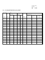
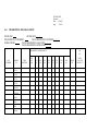
FLURAU-2.SOP
Revision #
1
Date:
03/10/98
Page
1 of 20
STANDARD OPERATING PROCEDURE
FOR THE MEASUREMENT OF
FLUOROMETRY IN
WATER AND SEAWATER USING
A MODEL 10-AU TURNER FLUOROMETER
PREPARED BY:
Shannon Lee
FOR:
Water Quality Laboratory (at NAUTICUS)
Applied Marine Research Laboratory
College of Sciences
Old Dominion University
Norfolk, Virginia 23529-0456
DOCUMENT FILE
LOCATION:
Quality Assurance Office
AMRL
EFFECTIVE DATE:
April, 1997
TERMINATION DATE:
APPROVED BY:
Dr. Alan W. Messing
Associate Director, AMRL
Joseph G. Winfield
Quality Assurance Officer, AMRL
DISCLAIMER:
Date
Date
This SOP applies to the analysis of marine and estuarine water samples in support
of the USEPA Chesapeake Bay Water Quality Monitoring Program for samples
collected in the Chesapeake Bay and Elizabeth River. This SOP may not be
applicable to any other studies.
FLURAU-2.SOP
Revision #
1
Date:
03/10/98
Page
2 of 20
TABLE OF CONTENTS
Title Page.........................................................................................................................................1
Table of Contents ............................................................................................................................2
1.
LOCATION.........................................................................................................................3
2.
PURPOSE............................................................................................................................3
3.
APPLICABILITY................................................................................................................3
4.
OVERVIEW OF METHOD...............................................................................................3
5.
APPARATUS ......................................................................................................................4
6.
INSTRUMENT MAINTENANCE ...................................................................................6
7.
ONBOARD PREPARATION............................................................................................9
8.
VERTICAL SAMPLING.................................................................................................12
9.
HORIZONTAL SAMPLING...........................................................................................13
10.
INTERNAL DATA LOGGER SHUT-DOWN ...............................................................14
11.
LAPTOP COMPUTER SHUT-DOWN ...........................................................................14
12.
PROCEDURES FOR COLLECTION AND CONCENTRATION OF
CALIBRATION SAMPLES ............................................................................................15
13.
POST-CRUISE ACTIVITIES ..........................................................................................16
14.
DEFINITIONS .................................................................................................................17
15.
FLUOROMETRY FIELD DATA SHEET ......................................................................18
16.
CHLOROPHYLL FIELD DATA SHEET.......................................................................19
17.
LITERATURE CITED.....................................................................................................20
FLURAU-2.SOP
Revision #
1
Date:
03/10/98
Page
3 of 20
1.0 LOCATION
This analytical procedure will be used by Water Quality Laboratory staff at NAUTICUS located at One
Waterside Drive, Norfolk, Virginia. The procedure will be performed at the field preparation section and
in the field for in situ monitoring.
2.0 PURPOSE
This procedure is designed to use a fluorometric technique to estimate chlorophyll a in estuarine and coastal
waters as an indicator of water quality and to provide estimates of chlorophyll a concentrations throughout
the study area for comparison to remote sensing data.
The intended user groups are the subcommittees and work groups of the USEPA Chesapeake Bay
Monitoring Program (CBP). These data will be used to assess the effectiveness of the multijurisdictional
action plan for restoring the water quality of the Chesapeake Bay. This assessment will include various
analyses of the data such as transectional data compilations and comparison with photosynthetic pigment
data collected using discrete grab samples at selected locations. These data may also be used for groundtruthing of remote sensing (e.g., satellite image) data. These data may also be used by State and Federal
government officials to implement management actions designed to help improve the quality of the water
in Chesapeake.
3.0 APPLICABILITY
This procedure is applicable to the continuous in vivo measurement of chlorophyll a in estuarine and coastal
waters. It can also be used for monitoring chlorophyll a in fresh water. The salinity ranges encountered in
the Chesapeake Bay are 0-36 parts per thousand.
The procedure assumes that spectrophotometric chlorophyll a data obtained from grab samples for
calibration purposes are accurate and that fluorescence of chlorophyll a using the excitation and emission
wavelengths specified in the procedure is proportional to the pigment concentration of the grab samples.
Chlorophyll a concentration is reported in units of Fg/L.
4.0 OVERVIEW OF METHOD
The procedure described in this SOP is based on the fluorescence of chlorophyll molecules at specific
wavelengths of light. At these wavelengths, the fluorescence of chlorophyll is proportional to ambient
chlorophyll concentration. A submersible sampling pump is used to pump ambient water through a flowthrough cuvette fitted to the fluorometer to provide in vivo measurement of chlorophyll concentrations.
Fluorometry data are collected using a laptop computer and internal data logger that captures data every
FLURAU-2.SOP
Revision #
1
Date:
03/10/98
Page
4 of 20
30 seconds. The position (latitude and longitude) and time (date and time stamp) for each discrete sample
or for continuous flow through measurements are recorded at 2 second intervals using a laptop computer
coupled to the fluorometer and Global Positioning System (GPS) with a differential beacon correction
system.
The data collected from the fluorometer are calibrated using spectrophotometry. Discrete water samples
are collected from the outlet port of the fluorometer flow-through system and analyzed using
spectrophotometric analysis for chlorophyll a concentration. These values are used to create a regression
equation that is used to interpolate chlorophyll a concentrations from fluorometric measurements.
Samples for fluorometry calibration are collected in brown plastic high density polyethylene (HDPE) sample
containers. Samples are buffered using 1 mL of saturated (1%) magnesium carbonate per 1000 mL of
sample then filtered on board immediately. The procedures for filtration, sample handling, preservation, and
analysis are described in the Chlorophyll: Spectrophotometric Method SOP.
5.0 APPARATUS
5.1
Field
5.1.1
Labware - Use only class A glassware
For vertical and horizontal grab samples:
20 ea. - 1000 mL brown HDPE (High Density Polyethylene) chlorophyll sample bottles
for each sampling day
6 ea. - filtration towers
2 ea. - 500 mL graduated cylinders
2 ea. - 1000 mL graduated cylinders
1 ea. - 4000 mL filtration flasks
2 ea. - Forceps with rounded tips
2 ea. - 2000 mL or 4000 mL filtration flasks
Ultrapure water squirt bottles
Labels for aluminum foil
Labels for sample bottles
Aluminum foil for chlorophyll filter pads
Notebook with fluorometry field data sheets
Black ink pens
5.1.2
Reagents
FLURAU-2.SOP
Revision #
1
Date:
03/10/98
Page
5 of 20
250 ml 1% MgCO3
FLURAU-2.SOP
Revision #
1
Date:
03/10/98
Page
6 of 20
5.1.3
Instruments
Turner Model 10-AU series fluorometer
Power cable with computer connector to fluorometer
2 Laptop computers with mouse
2 power cables for computers
Sampling array
40 lb weight attached to bottom of "T" frame
2 each "3AG 3AMP SLO-BLO" and "3AB 1/2AMP SLO-BLO" spare fuses
Set of Allen wrenches
Spare cuvette and O-rings
Silicon grease
Connecting hoses:
1 green plastic garden hose labeled BB
1 green plastic garden hose labeled C
1 green plastic garden hose labeled AA
Plastic Y-valve
Plastic T-valve pipe
5.2
Laboratory
5.2.1
Labware Needed:
Use only Class A volumetric labware
1 ea. - 100 mL volumetric flasks
5.2.2
Labware Cleaning
To clean volumetric flasks, filtration towers, flasks, graduated cylinders, and sample bottles:
Inspect labware for reside, breaks or defects. Clean labware by scrubbing with a bottle brush and
dilute Liquinox7 soap. Thoroughly rinse with tap water. Rinse twice with 4N hydrochloric acid
(HCL), then 9 times with fresh ultrapure water, ensuring that the entire inside surfaces are rinsed
each time. Inspect again for reside, breaks or defects. If not evident, dry on a clean drying rack
(labelled "for clean labware only"), completely covered with clean paper towels.
When dry, store volumetric flasks, vials and sample bottles with the caps on. Seal the tops of
filtration flasks, graduated cylinders, and Erlenmeyer flasks, and the tops and bottoms of filtration
towers with parafilm. Store in the appropriate cabinet.
FLURAU-2.SOP
Revision #
1
Date:
03/10/98
Page
7 of 20
5.2.3
Reagents
CHEMICALS USED AND REAGENT PREPARATION
Chemicals Used: All chemicals must be analytical grade or of a higher purity except as noted.
Magnesium carbonate (MgCO3)
Wash down the counter top or hood with ultrapure water and wipe dry using a paper towel before
and after preparing reagents.
The following information must be recorded on each reagent bottle label:
Reagent (name) and concentration:
Analysis (which requires this reagent):
Date prepared:
Prepared by: (initials)
Expiration date: (entry is N/A if there is no holding time)
Storage requirements (e.g. room temperature, 4EC, dark, etc.):
NOTE: Refer to Safety Precautions and use care when preparing reagents and stock
solutions.
Reagent containers are used only for the intended reagent and are reused. Before new reagents
are added to the containers, the containers are rinsed 9 times with ultrapure water, inspected, then
rinsed 3 times with the fresh reagent that they will contain.
Magnesium carbonate suspension: Measure 100 mL of fresh ultrapure water using a class A
volumetric flask. Add 1 g of finely powered magnesium carbonate. Shake immediately before use
until all material is in suspension.
6.0
INSTRUMENT MAINTENANCE AND SERVICE
6.1
Preventive Maintenance - Pre and Post Cruise
Flush fluorometer with ultrapure water no later than the morning after every cruise.
FLURAU-2.SOP
Revision #
1
Date:
03/10/98
Page
8 of 20
Visually inspect continuous flow cuvette after every cruise. Refer to section 6.2 of this SOP for
procedure.
Clean continuous flow cuvette with 4N HCl and rinse with ultrapure water. Refer to section 6.2
of this SOP for procedure.
If cuvette is scratched or cracked, replace. Refer to section 6.3 of this SOP for procedure.
Each time the cuvette is removed, visually inspect O-rings. If damaged, change O-rings.
Lubricate O-rings with silicon grease.
6.2
Cleaning the Cuvette
Removal and cleaning of the continuous flow cuvette is an in-laboratory procedure only.
Please refer to the diagram of the fluorometer in the Turner manufacturer's manual on
page A7-13 while following these steps.)
Turn off the power and drain all water from the system.
Remove all connections from the Intake and Exhaust fittings. Remove the four small screws on
both the Intake and Exhaust fittings with an allen wrench.
Remove the 3 screws that anchor the Intake fittings.
Remove the 8 screws which retain the sample compartment cover. If the gasket under this cover
sticks, remember that it is glued to the cover. Insert a thin knife gently between the gasket and the
sample Compartment Casing to loosen.
Using an Allen wrench, loosen the Upper and Lower Set Screws.
Pull the exhaust fitting top out of the holder, rotating it back and forth to free it.
BE CAREFUL! The cuvette may come out with the exhaust fitting. When this happens, remove
it with the exhaust fitting.
Remove the lower intake fitting in the same manner as the upper fitting. If the cuvette did
not come out with the Exhaust fitting, it should come out with the Intake fitting.
Wipe up any spilled liquids in the instrument and dry thoroughly to remove any saltwater that is
highly corrosive to metal components.
FLURAU-2.SOP
Revision #
1
Date:
03/10/98
Page
9 of 20
Clean the cuvette with 4N HCL and rinse with ultrapure water. If this will not clean the cuvette,
soak it in dilute acetic acid then rinse in Milli-Q water. Dry with lens tissue or Kimwipes.
Inspect the Intake and Exhaust fittings for any salt residue. Clean with Lime-Away and rinse with
Milli-Q if necessary.
Carefully inspect the two "O" rings on the exhaust fitting and on the intake fitting. If there are any
signs of nicks, tears or deterioration, replace with new "O" rings. The "O" rings are Nitrile (Bunda
N) rubber, therefore chemical resistance is good.
Lubricate the "O" rings with silicon grease using lubricant in the "O" ring replacement kit. The "O"
rings must be lubricated before installation.
6.3
Installation of the continuous flow cuvette:
Ensure that the cuvette is clean and that the "O" rings have been lubricated.
Position the cuvette securely onto the Intake fitting.
Insert the cuvette into the bottom opening of the fluorometer by holding the Intake fitting.
Insert the Exhaust fitting into the top opening of the fluorometer.
Rotate the Intake and Exhaust fittings slowly back and forth until the cuvette is properly aligned with
the fittings.
CAUTION: Excess force can easily break the fragile cuvette.
Tighten the Upper and Lower Set Screws.
Wipe off any fingerprints on the cuvette.
To make a visual inspection for leakage, move the instrument to the dish washing section and place
it on the side of the sink near the ultra-pure system.
Connect the tubing from the end of the ultra-pure system to the bottom connection of the flow
through cell and turn on the flow of water.
FLURAU-2.SOP
Revision #
1
Date:
03/10/98
Page
10 of 20
Make sure that the over flow from the top fitting runs in the sink. If leakage occurs the installation
process must be repeated.
Replace the front cover and the Intake and Exhaust fittings and screws.
7.0
ONBOARD PREPARATION
7.1
Fluorometer
Position the fluorometer so that the instrument panel faces you.
Uncap the power connector at the bottom right front of the fluorometer.
Line up the power cable with the connector and screw in the cable. The cable must be pushed in
and screwed tightly in stages to be fully connected.
Plug the power cable into the nearest electrical outlet.
Connect the computer cable to the laptop computer that is designated for use with the fluorometer.
7.2
Hose Arrangement
Screw the end of the hose labelled A to the intake (bottom) fitting of the fluorometer.
Screw the end of the hose labelled AA to the end of the T-valve labelled AA.
Screw the end of the hose labelled B to the exhaust (top) fitting. This is a short piece of hose with
a Y-valve on one end.
Screw the end of the hose labelled BB to the fittings on the V-valve labelled BB, this valve is left
open (parallel to the direction of flow) at all times so water can flow freely through the cuvette. The
end of this hose is laid out on the deck of the ship so the water goes overboard.
Screw the end of the hose labelled C hose to the end of the T-valve labelled C.
Screw the other end of the hose labelled C to the valve on the hull pump.
When doing a vertical profile, the end of the hose from the exhaust hose of the submersible pump
is connected to the T valve labelled D. As quickly as possible, turn off the water flow from the
FLURAU-2.SOP
Revision #
1
Date:
03/10/98
Page
11 of 20
hose labelled C and turn on the valve to the hose labelled D. Water should flow from the
submersible pump into D connection, through the T-valve, then into the end of the hose labelled
AA. From this point the water flows through the fluorometer and out the exhaust of the hose
labelled BB.
7.3
Internal Data Logger
After attaching the hoses to the fluorometer and ensuring that there are no leaks:
Turn on the fluorometer by pressing the red button on the front panel and allow it to warm up for
a minimum of 10 minutes. The HOME screen should be visible on the fluorometer.
Press <ENT> to access the Main Menu.
Press <5> to choose the Internal Data Logger menu.
Press <3> to choose Status.
Press <ENT> to toggle between "stop" and "logging". The internal data logger is now collecting
data.
Press <ESC> 3 times to get back to the HOME screen. "Logging data" should be displayed on
the screen and raw data will appear.
While data is logging, numbers on the keypad can be pressed to mark events:
1 - start Vertical Fluorometry profile (0.5m)
3 - start Horizontal Fluorometry profile
4 - end Horizontal Fluorometry profile
5 - Horizontal grab
6 - Vertical grab
8 - each depth during the Vertical profile (1m, 2m, 3m, 6m, 9m, ...) This is not pressed if a vertical
grab is taken and 6 has been pressed.
7.4
Laptop Computer for Fluorometer
Ensure that the fluorometer is connected to the laptop.
FLURAU-2.SOP
Revision #
1
Date:
03/10/98
Page
12 of 20
Connect the mouse and power cables to the appropriate ports on the computer.
Plug the power cable into the nearest electrical outlet.
Turn the computer on by pressing the green power button.
At the C:\ prompt, type win.
Click on OK if a New Mail message appears.
The computer should be in the Collect/W Jr.´ software. If not, double click on this icon.
Click on Instruments from the main menu.
Choose Open Instrument from the drop menu.
Choose Fluorometer from the menu.
Click on Open.
In Instrument Data Destination click on File. An X should appear in the box beside File.
Name the file C:\COLLECT\DATA\FLMM-DD.DAT
Where:
MM is the month
DD is the day
Click on OK.
The laptop should now be collecting data.
7.5
Laptop Computer for GPS
Plug in the GPS and turn on the power to the GPS and to the differential beacon.
Allow the GPS to warm up for approximately 15 min.
Ensure that the GPS is connected to the appropriate laptop computer.
Connect the mouse and power cables to the appropriate ports on the computer.
Plug the power cable into the nearest electrical outlet.
Turn the computer on by pressing the green power button.
At the C:\ prompt, type win.
FLURAU-2.SOP
Revision #
1
Date:
03/10/98
Page
13 of 20
Click on OK if a New Mail message appears.
The computer should be in the Collect/W Jr. software. If not, double click on this icon.
Click on Instruments from the main menu.
Choose Open Instrument from the drop menu.
Choose GPS from the menu.
Click on Open.
In Instrument Data Destination click on File. An X should appear in the box beside File.
Name the file C:\COLLECT\DATA\GPSMM-DD.DAT
Where:
MM is the month
DD is the day
Click on OK.
The laptop should now be collecting data from the GPS.
8.0 VERTICAL PROFILE SAMPLING
8.1
Vertical profile
At 1m depth, fill the surface carboy with water from the submersible pump hose. Place the exhaust
hose of the submersible pump onto the T-valve labelled D, and using the valves on the T-valve
open the valve to the hose labelled D and close the valve to the hose labelled C. Water should
now be flowing through the valve labelled D, into the T-valve, then into the hose labelled AA,
through the fluorometer and out the exhaust hose.
To begin the vertical profile, bring the array up to 0.5m, let the water flush through the hoses and
fluorometer for 1.5 min (this includes the 45 seconds flush time for the submersible pump and the
additional hoses). Record this as the start of the vertical profile by pressing 1 on the fluorometer
keypad. Record the event number, time the event was made, and event depth on the fluorometry
field sheet (Appendix 1).
After 0.5m, repeat the previous steps at 1m, 2m, 3m, and every 3m intervals thereafter to the
bottom. Press 8 on the fluorometer keypad to mark these events.
After the last vertical profile is completed at the last station to be sampled, the recording session
can be ended.
8.2
Vertical Grab Samples
FLURAU-2.SOP
Revision #
1
Date:
03/10/98
Page
14 of 20
A "grab" is sample water that has passed through the fluorometer, filtered and analyzed for
chlorophyll a using the SOP for Chlorophyll: Spectrophotometric Method and then correlated to
its corresponding value on the fluorometer for a calibration curve.
Two sets of grab samples (10 each) are taken for two calibrations, one is for vertical profiles and
the other is for horizontal profiles.
For vertical profiles try to collect one at each sampling station covering the range of fluorometry
values observed on the digital read out on the fluorometer. Collect 10 vertical grabs per cruiseday.
A grab sample is collected by opening the valve to the hose labelled BB, and filling a 1 L brown
HDPE chlorophyll bottle to the shoulder following the procedures in Section 12.1 of this SOP.
Press 6 on the fluorometer keypad to mark this event. After collecting the sample, close the valve.
Add 1 mL of magnesium carbonate suspension to the bottle. The sample should be filtered
immediately.
After the profile is completed, the T valve labelled D is closed, the valve labelled C is opened and
the end of the submersible pump is removed to allow the bottom sample to be collected in the
appropriate carboy.
9.0 HORIZONTAL PROFILE SAMPLING
9.1
Horizontal Profile
A horizontal profile is taken between each station. The profile is started as soon as the boat begins
to move toward the next station. Press 3 on the fluorometer keypad to mark this event.
Check to make sure the valve for the hull pump is turned on.
Open the T-valve to the hose labelled C and close the valve to the hose labelled D. Water should
now be flowing through the hose labeled CC into the T-valve, then into the hose labeled AA,
through the fluorometer and out the exhaust hose labelled BB.
During the horizontal profile, GPS coordinates are collected on the laptop computer.
Horizontal fluorometry is terminated upon arrival at the next station. Press 4 on the fluorometer
keypad to mark this event.
After the last vertical profile is completed at the last station to be sampled, the recording session
can be ended.
FLURAU-2.SOP
Revision #
1
Date:
03/10/98
Page
15 of 20
9.2
Horizontal Grab Samples
A grab sample is taken by opening the valve to the hose labelled BB, filling a 1.0 L brown HDPE
chlorophyll bottle to the shoulder following the procedures in Section 12.1 of this SOP. Press 5
on the fluorometer keypad to mark this event. After collecting the sample, close the valve. The
samples are processed the same way as the vertical profile samples.
For horizontal profiles, 10 grab samples are collected to cover all ranges observed on the digital
display on the fluorometer. Collect not less than 10 horizontal grabs per cruise-day.
10.0
INTERNAL DATA LOGGER SHUT-DOWN
Eliminate the water supply by turning off both the hull pump and the submersible flows to the
fluorometer.
On the fluorometer keypad:
Press <ENT> on the fluorometer keypad to access the Main Menu.
Press <5> to choose the Internal Datalogger menu.
Press <3> to choose Status.
Press <ENT> to toggle from "Logging" to "Stop".
Turn off the power to the fluorometer.
11.0
LAPTOP COMPUTER SHUT-DOWN
Close the Fluorometer (or GPS) window. Click on OK.
Close the Collect/W Jr. software.
Close the Program Manager window. Click on OK.
At the C:\ prompt, type cd collect\data and press Enter.
Type dir to view a list of the files in this directory.
11.1
Fluorometer Laptop
Insert a disk into the A:\ drive.
At the C:\ prompt, type copy FLMM-DD.DAT A:\ and press Enter.
Make a duplicate copy to be stored in a separate location
Press the power button to turn off the computer after the file has been copied to the disk.
11.2
GPS Laptop
FLURAU-2.SOP
Revision #
1
Date:
03/10/98
Page
16 of 20
At the C:\COLLECT\DATA prompt, type pkzip GPSMM-DD.zip MONTHGPS.ZIP and press
Enter.
Insert a disk into the A:\ drive.
At the C:\ prompt, type copy MONTHGPS.ZIP A:\ and press Enter.
Make a duplicate copy to be stored in a separate location.
Press the power button to turn off the computer after the file has been copied to the disk.
12.0
PROCEDURES FOR COLLECTION AND CONCENTRATION OF CALIBRATION
SAMPLES
12.1
Collection
To protect the chlorophyll from degradation prior to extraction and analysis, collect samples in
1000 mL brown HDPE bottles. Rinse the entire inside surface of the sample bottle three times with
sample, completely discarding the sample before successive rinses.
Fill the sample bottle with sample, leaving approximately one inch of air space in the sample bottle.
Immediately add 1 mL of magnesium carbonate suspension per liter of sample and invert to mix
(see definitions, section 14.0). Protect from direct sunlight.
Samples should be concentrated onto filters immediately after collection (section 12.2). If this is
not possible, store samples at 4EC by refrigerating or packing the sample bottles in ice up to the
level of the sample but below the bottom of the sample bottle cap. Keep container lids closed as
much as possible. Storage temperature must be measured using a thermometer which has been
calibrated against an NIST-traceable thermometer within the last six months. Storage temperature
must be documented.
12.2
Concentration
Labware needed:
6 ea. 2 ea. 2 ea. 1 ea. -
filtration towers
500 mL graduated cylinders
1000 mL graduated cylinders
4000 mL filtration flasks
FLURAU-2.SOP
Revision #
1
Date:
03/10/98
Page
17 of 20
2 ea. - Forceps with rounded tips
2 ea. - 2000 mL or 4000 mL filtration flasks
4.25 cm Whatman7 GF/F glass fiber filters (box of 100)
Ultrapure water squirt bottles
Labels for aluminum foil
Labels for sample bottles
Aluminum foil for chlorophyll filter pads
Notebook with fluorometry field data sheets
Black ink pens
See section 5.2.2 for the appropriate labware cleaning procedures.
Using forceps, gripping only the filter edge, transfer a 4.25 cm Whatman7 GF/F glass fiber
filter onto the base of a filtration tower. Replace the top of the filtration tower onto the
base.
Moisten the filter with ultrapure water.
Rinse the entire inside surface of a 500 mL graduated cylinder three times with ultrapure water.
Mix the sample thoroughly by inverting (see definitions) the sample bottle 20 times. Immediately
rinse the graduated cylinder twice with the sample to be concentrated.
Mix the sample thoroughly by inverting the sample bottle 20 times. Immediately pour a
pre-determined volume of sample into the rinsed graduated cylinder. Record the filtration
volume in the appropriate space on the chlorophyll field data sheet.
Concentrate the phytoplankton by filtering the sample water through the filter using 12 KPa
vacuum pressure. To avoid cell damage during filtration, do not exceed this vacuum
pressure and limit filtration duration to 5 minutes or less. If it takes longer than 5 minutes
to filter the selected sample volume, discard filter and remaining sample, rinse the filtration
tower and refilter using a smaller sample volume.
Fold the filter in half using forceps, being careful not to contact or disturb the filtrate. Place the
folded filter on a labelled square of aluminum foil and seal tightly.
Freeze as soon as possible at -20EC to -70EC. If freezing immediately is not possible, refrigerate
or store in a water and light tight container packed in ice and freeze as soon as possible.
Completely rinse (with the vacuum applied) the empty filtration tower three times with ultrapure
water before seating a new filter for the next sample.
Repeat the above steps for each sample.
FLURAU-2.SOP
Revision #
1
Date:
03/10/98
Page
18 of 20
13.0 POST-CRUISE ACTIVITIES
13.1
Downloading Fluorometry Data
Plug the cord from the fluorometer into the port at the back of the computer where the modem is
located. The port is labelled A.
Ensure that the fluorometer is plugged in. Turn the fluorometer on by pressing the red power button
on the front panel.
On the computer:
Log in to the computer by typing your login name and password. Press Enter.
Select 6 from the Main Menu to return to the DOS prompt.
Type H:\ and press Enter
At the DOS prompt type IDL_1B1. Press Enter.
Select <6> from the Main Menu. This option allows you to download data and convert
the file to ASCII in one step.
On the fluorometer:
Using the fluorometer keypad press <ENT> to exit the HOME screen.
Press <5> to choose Internal Data Logger from the Main Menu.
Press <4> to access the downloading sequence.
Press <8> five times to start downloading.
On the computer:
When downloading is complete, the program will prompt you to name the file. The
filename should be CBP###.BIN. Where ### = cruise number.
The program will then prompt you to name the ACSII file.
The ASCII filename should be CBP###.PRN. Where ### = cruise number.
13.2
Press <9> to exit the program.
Maintenance : See section 6.0 of this SOP. Should be performed after every cruise.
13.3
Storage : The fluorometer is stored in the cruise prep area until the next cruise.
FLURAU-2.SOP
Revision #
1
Date:
03/10/98
Page
19 of 20
14.0 DEFINITIONS
HPDE: High-density polyethylene
invert: In reference to homogenizing a sample be inverting, one inversion is: starting with the cap of the
sample bottle pointing straight up, turn the sample bottle completely upside down so the cap is
pointing straight down, then turn the sample bottle upright until the cap is pointing straight up again.
FLURAU-2.SOP
Revision #
1
Date:
03/10/98
Page
20 of 20
15.0
FLUOROMETRY FIELD DATA SHEET
Cruise #: CBP
Date:
Loran Coord.
Event
#
Time
Lat.
Light (Fmol/sec/m2)
Station
Long.
Dep
Des
Depth
Air
(Ch. 1)
Water Up
(Ch. 2)
Water
Down
(Ch. 3)
FLURAU-2.SOP
Revision #
1
Date:
03/10/98
Page
21 of 20
16.0
CHLOROPHYLL FIELD DATA SHEET
CRUISE CBP
CRUISE DATE / /
CHLOROPHYLL FILTERED BY
DATE CHLOROPHYLL FILTERED
EXTRACTED BY
DATE CHLOROPHYLL ANALYZED / /
DATE CHLOROPHYLL EXTRACTED / /
/
/
CHLOROPHYLL ABSORBANCES
LOG
NUMBER
SAMPLE
ID
EE3.4 S
EE3.4 B
EE3.5 S
EE3.5 B
CB5.4W S
CB5.4W B
CB5.4 S
CB5.4
CB5.4
CB5.4 B
TIME
FILTERED
VOL
S/E
l/ml
750
(A)
664
(A)
647
(A)
664/
665
630
(A)
480
(A)
510
(A)
750a
(A)
665a
(A)
DONE
BY
RATIO
(CAN NOT
EXCEED 1.7)
FLURAU-2.SOP
Revision #
1
Date:
03/10/98
Page
22 of 20
17.0
LITERATURE CITED
APHA. 1989. Standard Methods for the Examination of Water and Wastewater. 17th Edition. Method 10200 H.
Chlorophyll. American Public Health Association. Washington, DC.
ASTM. 1979. Standard Practices for Measurement of Chlorophyll Content of Algae in Surface Waters. Method D373179. American Society for Testing and Materials. Philadelphia, PA.
Model 10-AU-005 Field Fluorometer User's Manual. October 1993. Order Number 998-5313.