1
MAKING MODERN LIVING POSSIBLE
Design Guide
VLT® Micro Drive FC 51
www.danfoss.com/drives
VLT® Micro Drive FC 51 Design Guide
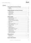
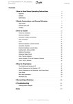
Contents
Contents
1 Introduction
5
1.1 Available Literature
5
1.2 Document and Software Version
5
1.3 Abbreviations
5
1.4 Definitions
6
1.5 Power Factor
8
2 Safety and Conformity
9
2.1 Safety
9
2.2 Disposal Instruction
10
2.3 Approvals
10
2.4 CE Labeling
10
2.5 Aggressive Environments
11
2.6 Vibration and Shock
12
2.7 Advantages
12
3 Product Overview
18
3.1 Control Structures
18
3.1.1 Control Structure Open Loop
18
3.1.2 Local (Hand On) and Remote (Auto On) Control
18
3.1.3 Control Structure Closed Loop
19
3.1.4 Reference Handling
20
3.2 General Aspects of EMC
3.2.1 Emission Requirements
21
22
3.3 Galvanic Isolation (PELV)
23
3.4 Earth Leakage Current
24
3.5 Extreme Running Conditions
24
3.5.1 Motor Thermal Protection
4 Selection
25
26
4.1 Options and Accessories
26
4.1.1 Local Control Panel (LCP)
26
4.1.2 Remote Mounting Kit for LCP
26
4.1.3 FC 51 LCP Mounting Instruction
27
4.1.4 FC 51 Remote Mounting Kit Mounting Instruction
27
4.1.5 IP21/TYPE 1 Enclosure Kit
29
4.1.6 Type 1 (NEMA)
29
4.1.7 De-Coupling
29
4.1.8 FC 51 Type 1 Kit Mounting Instruction for M1, M2 and M3
30
4.1.9 FC 51 Type 1 Kit Mounting Instruction for M4 and M5
30
MG02K302 - Rev. 2013-12-03
1
VLT® Micro Drive FC 51 Design Guide
Contents
4.1.10 FC 51 IP21 Kit Mounting Instruction
31
4.1.11 FC 51 De-coupling Plate Mounting Instruction for M1 and M2
32
4.1.12 FC 51 De-coupling Plate Mounting Instruction for M3
32
4.1.13 FC 51 De-coupling Plate Mounting Instruction for M4 and M5
33
4.1.14 FC 51 DIN Rail Kit Mounting Instruction
34
4.1.15 Line Filter MCC 107 Installation Instructions
34
4.1.16 Mounting
35
4.1.17 Wiring
35
4.1.18 Dimensions
36
4.2 Special Conditions
37
4.2.1 Purpose of Derating
37
4.2.2 Derating for Ambient Temperature
37
4.2.3 Derating for Low Air Pressure
38
4.2.4 Automatic Adaptations to Ensure Performance
38
4.2.5 Derating for Running at Low Speed
38
5 How to Order
39
5.1 Drive Configurator
39
5.2 FC Identification
39
5.3 Type Code
40
5.4 Ordering Numbers
41
5.5 Options
41
6 How to Install
43
6.1 Before Starting
43
6.2 Side-by-Side Installation
43
6.3 Before Commencing Repair Work
43
6.4 Mechanical Dimensions
44
6.5 Electrical Installation in General
44
6.6 Fuses
45
6.7 Mains Connection
46
6.8 Motor Connection
46
6.9 Use of EMC-Correct Cables
49
6.10 Earthing of Screened/Armoured Control Cables
50
6.11 Residual Current Device
50
6.12 Electrical Overview
51
6.12.1 Power Circuit - Overview
2
51
6.13 Electrical Installation and Control Cables
52
6.14 Control Terminals
52
6.14.1 Access to Control Terminals
52
6.14.2 Connecting to Control Terminals
53
MG02K302 - Rev. 2013-12-03
VLT® Micro Drive FC 51 Design Guide
Contents
6.15 Switches
53
6.16 Final Set-Up and Test
53
6.17 Parallel Connection of Motors
55
6.18 Motor Installation
56
6.19 Installation of Misc. Connections
56
6.20 Safety
57
6.20.1 High Voltage Test
57
6.20.2 Safety Earth Connection
57
7 Programming
58
7.1 How to Programme
58
7.1.1 Programming with MCT 10 Set-up Software
58
7.1.2 Programming with the LCP 11 or LCP 12
58
7.2 Status Menu
59
7.3 Quick Menu
59
7.4 Quick Menu Parameters
60
7.5 Main Menu
63
7.6 Quick Transfer of Parameter Settings between Multiple Frequency Converters
63
7.7 Read-out and Programming of Indexed Parameters
63
7.8 Initialise the Frequency Converter to Default Settings in two Ways
64
8 RS-485 Installation and Set-up
65
8.1 RS-485 Installation and Set-up
65
8.1.1 Overview
65
8.1.2 Network Connection
65
8.1.3 Frequency Converter Hardware Set-up
65
8.1.4 EMC Precautions
66
8.2 FC Protocol Overview
66
8.3 Network Configuration
67
8.4 FC Protocol Message Framing Structure
67
8.4.1 Content of a Character (byte)
67
8.4.2 Telegram Structure
67
8.4.3 Telegram Length (LGE)
67
8.4.4 Frequency Converter Address (ADR)
68
8.4.5 Data Control Byte (BCC)
68
8.4.6 The Data Field
68
8.4.7 The PKE Field
69
8.4.8 Parameter Number (PNU)
69
8.4.9 Index (IND)
69
8.4.10 Parameter Value (PWE)
69
8.4.11 Data Types Supported by the Frequency Converter
70
MG02K302 - Rev. 2013-12-03
3
VLT® Micro Drive FC 51 Design Guide
Contents
8.4.12 Conversion
70
8.5 Examples
70
8.6 Modbus RTU Overview
71
8.6.1 Assumptions
71
8.6.2 What the User Should Already Know
71
8.6.3 Modbus RTU Overview
71
8.6.4 Frequency Converter with Modbus RTU
72
8.7 Network Configuration
72
8.8 Modbus RTU Message Framing Structure
72
8.8.1 Frequency Converter with Modbus RTU
72
8.8.2 Modbus RTU Message Structure
72
8.8.3 Start/Stop Field
73
8.8.4 Address Field
73
8.8.6 Data Field
73
8.8.7 CRC Check Field
73
8.8.8 Coil Register Addressing
73
8.8.9 How to Control the Frequency Converter
75
8.8.10 Function Codes Supported by Modbus RTU
75
8.8.11 Modbus Exception Codes
76
8.9 How to Access Parameters
76
8.9.1 Parameter Handling
76
8.9.2 Storage of Data
76
8.9.3 IND (Index)
76
8.9.4 Text Blocks
76
8.9.6 Parameter Values
76
8.10 Examples
77
8.10.1 Read Coil Status (01 hex)
77
8.10.2 Force/Write Single Coil (05 hex)
77
8.10.3 Force/Write Multiple Coils (0F hex)
78
8.10.4 Read Holding Registers (03 hex)
78
8.10.5 Preset Single Register (06 hex)
78
8.10.6 Preset Multiple Registers (10 hex)
79
8.11 FC Drive Control Profile
4
79
8.11.1 Control Word According to FC Profile (8-10 Protocol = FC profile)
79
8.11.2 Status Word According to FC Profile (STW) (8-30 Protocol = FC profile)
81
8.11.3 Bus Speed Reference Value
82
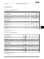
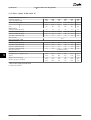
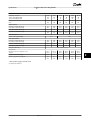
9 Specifications
83
Index
89
MG02K302 - Rev. 2013-12-03
VLT® Micro Drive FC 51 Design Guide
Introduction
1 1
1 Introduction
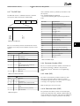
1.1 Available Literature
1.3 Abbreviations
NOTICE
°C
Degrees Celsius
A
Ampere/AMP
AC
Alternating current
AMT
Automatic Motor Tuning
AWG
American wire gauge
DC
Direct current
EMC
Electro Magnetic Compatibility
This design guide contains the basic information
necessary for installing and running the frequency
converter.
Danfoss technical literature is available in print from local
Danfoss Sales Offices or online at: www.danfoss.com/
BusinessAreas/DrivesSolutions/Documentations
•
•
•
•
VLT Micro Drive FC 51 Quick Guide, MG02B
VLT Micro Drive FC 51 Programming Guide, MG02C
FC 51 LCP Mounting Instruction, MI02A
ETR
Electronic Thermal Relay
FC
Frequency Converter
fM,N
Nominal motor frequency
g
Gram
Hz
Hertz
IINV
Rated Inverter Output Current
FC 51 De-coupling Plate Mounting Instruction,
MI02B
ILIM
Current limit
IM,N
Nominal motor current
•
FC 51 Remote Mounting Kit Mounting Instruction,
MI02C
IVLT,MAX
The maximum output current
IVLT,N
•
•
•
•
FC 51 DIN Rail Kit Mounting Instruction, MI02D
The rated output current supplied by the
frequency converter
kHz
Kilohertz
FC 51 IP21 Kit Mounting Instruction, MI02E
LCP
Local Control Panel
FC 51 Nema1 Kit Mounting Instruction, MI02F
m
Meter
mA
Milliampere
MCT
Motion Control Tool
FC 51 Line Filter MCC 107 Installation Instruction,
MI02U
1.2 Document and Software Version
This manual is regularly reviewed and updated. All
suggestions for improvement are welcome. Table 1.1 shows
the document version and the corresponding software
version.
Edition
Remarks
Software Version
MG02K3XX
Replaces MG02K2XX
3.1X
Table 1.1 Document and Software Version
mH
Millihenry Inductance
min
Minute
ms
Millisecond
nF
Nanofarad
Nm
Newton Meters
ns
Synchronous Motor Speed
PM,N
Nominal motor power
PCB
Printed Circuit Board
PELV
Protective Extra Low Voltage
RPM
Revolutions Per Minute
Regen
Regenerative terminals
s
Second
TLIM
Torque limit
UM,N
Nominal motor voltage
V
Volts
Table 1.2 Abbreviations
MG02K302 - Rev. 2013-12-03
5
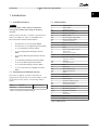
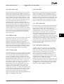
1.4 Definitions
Break-away torque
Torque
1.4.1 Frequency Converter
175ZA078.10
1 1
VLT® Micro Drive FC 51 Design Guide
Introduction
Pull-out
IVLT,MAX
The maximum output current.
IVLT,N
The rated output current supplied by the frequency
converter.
UVLT, MAX
The maximum output voltage.
1.4.2 Input
rpm
Control command
The connected motor can be started and stopped with LCP
and the digital inputs.
Functions are divided into 2 groups.
Functions in group 1 have higher priority than functions in
group 2.
Group 1
Reset, Coasting stop, Reset and Coasting stop,
Quick-stop, DC braking, Stop and the [Off] key.
Group 2
Start, Pulse start, Reversing, Start reversing, Jog
and Freeze output
Table 1.3 Function Groups
Illustration 1.1 Break-away Torque
ηVLT
The efficiency of the frequency converter is defined as the
ratio between the power output and the power input.
Start-disable command
A stop command belonging to the group 1 control
commands, see Table 1.3.
Stop command
See Control commands.
1.4.3 Motor
1.4.4 References
fJOG
The motor frequency when the jog function is activated
(via digital terminals).
Analog Reference
A signal transmitted to the analog inputs 53 or 54, can be
voltage or current.
fM
The motor frequency.
Bus Reference
A signal transmitted to the serial communication port (FC
port).
fMAX
The maximum motor frequency.
fMIN
The minimum motor frequency.
fM,N
The rated motor frequency (nameplate data).
IM
The motor current.
IM,N
The rated motor current (nameplate data).
nM,N
The rated motor speed (nameplate data).
PM,N
The rated motor power (nameplate data).
Preset Reference
A defined preset reference to be set from -100% to +100%
of the reference range. Selection of 8 preset references via
the digital terminals.
RefMAX
Determines the relationship between the reference input
at 100% full scale value (typically 10 V, 20 mA) and the
resulting reference. The maximum reference value set in
3-03 Maximum Reference.
RefMIN
Determines the relationship between the reference input
at 0% value (typically 0 V, 0 mA, 4 mA) and the resulting
reference. The minimum reference value set in
3-02 Minimum Reference
UM
The instantaneous motor voltage.
UM,N
The rated motor voltage (nameplate data).
6
MG02K302 - Rev. 2013-12-03
Introduction
VLT® Micro Drive FC 51 Design Guide
1.4.5 Miscellaneous
Analog Inputs
The analog inputs are used for controlling various
functions of the frequency converter.
There are 2 types of analog inputs:
•
•
Current input, 0-20 mA and 4-20 mA
Voltage input, 0-10 V DC.
Analog Outputs
The analog outputs can supply a signal of 0-20 mA, 4-20
mA, or a digital signal.
Automatic Motor Tuning, AMT
AMT algorithm determines the electrical parameters for the
connected motor at standstill.
Brake Resistor
The brake resistor is a module capable of absorbing the
brake power generated in regenerative braking. This
regenerative braking power increases the intermediate
circuit voltage and a brake chopper ensures that the
power is transmitted to the brake resistor.
CT Characteristics
Constant torque characteristics used for all applications
such as conveyor belts, displacement pumps and cranes.
Digital Inputs
The digital inputs can be used for controlling various
functions of the frequency converter.
Relay Outputs
The frequency converter features two programmable Relay
Outputs.
ETR
Electronic Thermal Relay is a thermal load calculation
based on present load and time. Its purpose is to estimate
the motor temperature.
Initialising
If initialising is carried out (14-22 Operation Mode), the
programmable parameters of the frequency converter
return to their default settings.
Initialising 14-22 Operation Mode does not initialise
communication parameters.
Intermittent Duty Cycle
An intermittent duty rating refers to a sequence of duty
cycles. Each cycle consists of an on-load and an off-load
period. The operation can be either periodic duty or noneperiodic duty.
LCP
The Local Control Panel makes up a complete interface for
control and programming of the frequency converter. The
control panel is detachable and can be installed up to 3 m
from the frequency converter, that is, in a front panel with
the installation kit option.
MCM
Short for Mille Circular Mil, an American measuring unit for
cable cross-section. 1 MCM ≡ 0.5067 mm2.
msb
Most significant bit.
On-line/Off-line Parameters
Changes to on-line parameters are activated immediately
after the data value is changed. Changes to off-line
parameters are not activated until pressing [OK].
PI Controller
The PI controller maintains the desired speed, pressure,
temperature, etc. by adjusting the output frequency to
match the varying load.
RCD
Residual Current Device.
Set-up
Save parameter settings in 2 set-ups. Change between the
2 parameter set-ups and edit one set-up, while another
set-up is active.
Slip Compensation
The frequency converter compensates for the motor slip
by giving the frequency a supplement that follows the
measured motor load keeping the motor speed almost
constant.
Smart Logic Control (SLC)
The SLC is a sequence of user-defined actions executed
when the associated user-defined events are evaluated as
true by the SLC.
Thermistor
A temperature-dependent resistor placed where the
temperature is to be monitored (frequency converter or
motor).
STW
Status Word.
FC Standard Bus
Includes RS 485 bus with FC protocol. See 8-30 Protocol.
Trip
A state entered in fault situations, e.g. if the frequency
converter is subject to an over-temperature or when the
frequency converter is protecting the motor, process or
mechanism. Restart is prevented until the cause of the
fault has disappeared and the trip state is canceled by
activating reset or, in some cases, by being programmed
to reset automatically. Trip may not be used for personal
safety.
lsb
Least significant bit.
MG02K302 - Rev. 2013-12-03
7
1 1
1 1
VLT® Micro Drive FC 51 Design Guide
Introduction
Trip Locked
A state entered in fault situations when the frequency
converter is protecting itself and requiring physical
intervention, for example, if the frequency converter is
subject to a short circuit on the output. A locked trip can
only be canceled by cutting off mains, removing the cause
of the fault, and reconnecting the frequency converter.
Restart is prevented until the trip state is canceled by
activating reset or, in some cases, by being programmed
to reset automatically. Trip locked may not be used for
personal safety.
VT Characteristics
Variable torque characteristics used for pumps and fans.
VVCplus
If compared with standard voltage/frequency ratio control,
Voltage Vector Control (VVCplus) improves the dynamics
and the stability, both when the speed reference is
changed and in relation to the load torque.
1.5 Power Factor
The power factor is the relation between I1 and IRMS.
Power factor =
3 × U × I 1 × COS ϕ
3 × U × IRMS
The power factor for 3-phase control:
=
I1 × cosϕ1
I1
=
since cosϕ1 = 1
IRMS
IRMS
The power factor indicates to which extent the frequency
converter imposes a load on the mains supply.
The lower the power factor, the higher the IRMS for the
same kW performance.
2 2
IRMS = I2
1 + I5 + I7 +
. . +
I2
n
In addition, a high-power factor indicates that the different
harmonic currents are low.
8
MG02K302 - Rev. 2013-12-03
Safety and Conformity
VLT® Micro Drive FC 51 Design Guide
2 Safety and Conformity
2 2
WARNING
2.1 Safety
The following symbols are used in this document:
WARNING
Indicates a potentially hazardous situation which could
result in death or serious injury.
CAUTION
Indicates a potentially hazardous situation which could
result in minor or moderate injury. It may also be used
to alert against unsafe practices.
NOTICE
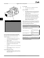
DISCHARGE TIME
The frequency converter contains DC-link capacitors,
which can remain charged even when the frequency
converter is not powered. Failure to wait the specified
time after power has been removed before performing
service or repair work, could result in death or serious
injury.
1.
Stop motor.
2.
Disconnect AC mains, permanent magnet type
motors, and remote DC-link power supplies,
including battery back-ups, UPS, and DC-link
connections to other frequency converters.
3.
Wait for the capacitors to discharge fully, before
performing any service or repair work. The
duration of waiting time is specified in
Table 2.1.
Indicates important information, including situations that
may result in damage to equipment or property.
2.1.1 Safety Precautions
Size
WARNING
4
M4 and M5
15
HIGH VOLTAGE
Frequency converters contain high voltage when
connected to AC mains input power. Failure to perform
installation, start-up, and maintenance by qualified
personnel could result in death or serious injury.
•
Installation, start-up, and maintenance must be
performed by qualified personnel only.
WARNING
Table 2.1 Discharge Time
WARNING
LEAKAGE CURRENT HAZARD
Leakage currents exceed 3.5 mA. Failure to ground the
frequency converter properly could result in death or
serious injury.
•
UNINTENDED START
When the frequency converter is connected to AC mains,
the motor may start at any time, causing risk of death,
serious injury, equipment, or property damage. The
motor can start by means of an external switch, a serial
bus command, an input reference signal from the LCP or
LOP, via remote operation using MCT 10 software, or
after a cleared fault condition.
•
Disconnect the frequency converter from mains
whenever personal safety considerations make
it necessary to avoid unintended motor start.
•
Press [Off/Reset] on the LCP, before
programming parameters.
•
The frequency converter, motor, and any driven
equipment must be in operational readiness
when the frequency converter is connected to
AC mains.
Minimum waiting time (min)
M1, M2 and M3
Ensure correct grounding of the equipment by
a certified electrical installer.
WARNING
EQUIPMENT HAZARD
Contact with rotating shafts and electrical equipment
can result in death or serious injury.
•
Ensure that only trained and qualified
personnel perform installation, start up, and
maintenance.
•
Ensure that electrical work conforms to national
and local electrical codes.
•
Follow the procedures in this manual.
MG02K302 - Rev. 2013-12-03
9
2 2
Safety and Conformity
VLT® Micro Drive FC 51 Design Guide
CAUTION
WINDMILLING
Unintended rotation of permanent magnet motors
causes risk of personal injury and equipment damage.
•
Ensure that permanent magnet motors are
blocked to prevent unintended rotation.
CAUTION
POTENTIAL HAZARD IN THE EVENT OF INTERNAL
FAILURE
Risk of personal injury when the frequency converter is
not properly closed.
•
Before applying power, ensure all safety covers
are in place and securely fastened.
2.2 Disposal Instruction
Equipment containing electrical
components may not be disposed of
together with domestic waste.
It must be separately collected with
electrical and electronic waste according
to local and currently valid legislation.
2.3 Approvals
information on safety aspects relating to the frequency
converter. Danfoss do this by means of a manufacturer's
declaration.
The low-voltage directive (73/23/EEC)
Frequency converters must be CE labeled in accordance
with the low-voltage directive of January 1, 1997. The
directive applies to all electrical equipment and appliances
used in the 50-1000 V AC and the 75-1500 V DC voltage
ranges. Danfoss CE-labels in accordance with the directive
and issues a declaration of conformity upon request.
The EMC directive (89/336/EEC)
EMC is short for electromagnetic compatibility. The
presence of electromagnetic compatibility means that the
mutual interference between different components/
appliances does not affect the way the appliances work.
The EMC directive came into effect January 1, 1996.
Danfoss CE-labels in accordance with the directive and
issues a declaration of conformity upon request. To carry
out EMC-correct installation, see the instructions in this
Design Guide. In addition, Danfoss specifies which
standards our products comply with. Danfoss offers the
filters presented in the specifications and provide other
types of assistance to ensure the optimum EMC result.
The frequency converter is most often used by professionals of the trade as a complex component forming part
of a larger appliance, system or installation. Not that the
responsibility for the final EMC properties of the appliance,
system or installation rests with the installer.
2.4.2 What is Covered
Table 2.2 Approvals
The frequency converter complies with UL508C thermal
memory retention requirements. For more information
refer to chapter 3.5.1 Motor Thermal Protection.
The EU "Guidelines on the Application of Council Directive
89/336/EEC" outline three typical situations of using a
frequency converter. See chapter 2.4.3 Danfoss Frequency
Converter and CE Labeling for EMC coverage and CE
labeling.
1.
The frequency converter is sold directly to the
end-consumer. The frequency converter is for
example sold to a DIY market. The end-consumer
is a layman. He installs the frequency converter
himself for use with a hobby machine, a kitchen
appliance, etc. For such applications, the
frequency converter must be CE labeled in
accordance with the EMC directive.
2.
The frequency converter is sold for installation in
a plant. The plant is built up by professionals of
the trade. It could be a production plant or a
heating/ventilation plant designed and installed
by professionals of the trade. Neither the
frequency converter nor the finished plant has to
be CE labeled under the EMC directive. However,
the unit must comply with the basic EMC
requirements of the directive. This is ensured by
2.4 CE Labeling
2.4.1 CE Conformity and Labeling
What is CE Conformity and Labeling?
The purpose of CE labeling is to avoid technical trade
obstacles within EFTA and the EU. The EU has introduced
the CE label as a simple way of showing whether a
product complies with the relevant EU directives. The CE
label says nothing about the specifications or quality of
the product. Frequency converters are regulated by 3 EU
directives:
The machinery directive (98/37/EEC)
All machines with critical moving parts are covered by the
machinery directive of January 1, 1995. Since a frequency
converter is largely electrical, it does not fall under the
machinery directive. However, if a frequency converter is
supplied for use in a machine, Danfoss provides
10
MG02K302 - Rev. 2013-12-03
Safety and Conformity
3.
VLT® Micro Drive FC 51 Design Guide
using components, appliances, and systems that
are CE labeled under the EMC directive.
2.4.4 Compliance with EMC Directive
89/336/EEC
The frequency converter is sold as part of a
complete system. The system is being marketed
as complete and could for example, be an airconditioning system. The complete system must
be CE labeled in accordance with the EMC
directive. The manufacturer can ensure CE
labeling under the EMC directive either by using
CE labeled components or by testing the EMC of
the system. If only CE labeled components are
chosen, the entire system does not have to be
tested.
As mentioned, the frequency converter is mostly used by
professionals of the trade as a complex component
forming part of a larger appliance, system, or installation.
Not that the responsibility for the final EMC properties of
the appliance, system or installation rests with the installer.
As an aid to the installer, Danfoss has prepared EMC installation guidelines for the Power Drive system. The standards
and test levels stated for Power Drive systems are
complied with, if the EMC-correct instructions for installation are followed.
2.4.3 Danfoss Frequency Converter and CE
Labeling
CE labeling is a positive feature when used for its original
purpose, that is, to facilitate trade within the EU and EFTA.
However, CE labeling may cover many different specifications. Check what a given CE label specifically covers.
The covered specifications can be very different and a CE
label may therefore give the installer a false feeling of
security when using a frequency converter as a component
in a system or an appliance.
Danfoss CE labels the frequency converters in accordance
with the low-voltage directive. This means that if the
frequency converter is installed correctly, Danfoss
guarantees compliance with the low-voltage directive.
Danfoss issues a declaration of conformity that confirms
our CE labeling in accordance with the low-voltage
directive.
The CE label also applies to the EMC directive provided
that the instructions for EMC-correct installation and
filtering are followed. On this basis, a declaration of
conformity in accordance with the EMC directive is issued.
The Design Guide offers detailed instructions for installation to ensure EMC-correct installation. Furthermore,
Danfoss specifies which our different products comply
with.
Danfoss provides other types of assistance that can help to
obtain the best EMC result.
The frequency converter has been designed to meet the
IEC/EN 60068-2-3 standard, EN 50178 9.4.2.2 at 50 °C.
2.5 Aggressive Environments
A frequency converter contains many mechanical and
electronic components. All are to some extent vulnerable
to environmental effects.
CAUTION
The frequency converter should not be installed in
environments with airborne liquids, particles, or gases
capable of affecting and damaging the electronic
components. Failure to take the necessary protective
measures increases the risk of stoppages, thus reducing
the life of the frequency converter.
Liquids can be carried through the air and condense in the
frequency converter and may cause corrosion of
components and metal parts. Steam, oil, and salt water
may cause corrosion of components and metal parts. In
such environments, use equipment with enclosure rating
IP54. As an extra protection, coated printed circuit boards
can be ordered as an option. (Standard on some power
sizes.)
Airborne particles such as dust may cause mechanical,
electrical, or thermal failure in the frequency converter. A
typical indicator of excessive levels of airborne particles is
dust particles around the frequency converter fan. In dusty
environments, use equipment with enclosure rating IP54 or
a cabinet for IP20/TYPE 1 equipment.
In environments with high temperatures and humidity,
corrosive gases such as sulphur, nitrogen, and chlorine
compounds causes chemical processes on the frequency
converter components.
Such chemical reactions rapidly affects and damages the
electronic components. In such environments, mount the
equipment in a cabinet with fresh air ventilation, keeping
aggressive gases away from the frequency converter.
MG02K302 - Rev. 2013-12-03
11
2 2
Before installing the frequency converter, check the
ambient air for liquids, particles, and gases. This is done by
observing existing installations in this environment. Typical
indicators of harmful airborne liquids are water or oil on
metal parts, or corrosion of metal parts.
Excessive dust particle levels are often found on installation cabinets and existing electrical installations. One
indicator of aggressive airborne gases is blackening of
copper rails and cable ends on existing installations.
120
A
80
40
Vibration, broad-band random
20
40
60
140
160
180
120
A
SYSTEM CURVE
100
80
FAN CURVE
B
60
40
C
Table 2.3 Standards
20
2.7 Advantages
0
20
40
60
80 100
Voume %
120
140
160
180
60
80
100
Voume %
120
140
160
180
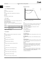
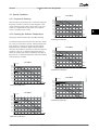
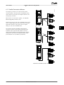
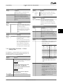
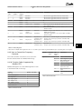
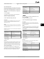
2.7.1 Why use a Frequency Converter for
Controlling Fans and Pumps?
A frequency converter takes advantage of the fact that
centrifugal fans and pumps follow the laws of proportionality for such fans and pumps. For further information
see chapter 2.7.3 Example of Energy Savings.
80
100 120
VOLUME%
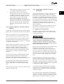
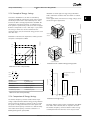
Illustration 2.1 Fan Curves (A, B, and C) for Reduced Fan
Volumes
PRESSURE %
IEC/EN 60068-2-64
C
20
The frequency converter complies with requirements that
exist for units mounted on the walls and floors of
production premises, as well as in panels bolted to walls or
floors.
Vibration (sinusoidal) - 1970
FAN CURVE
B
60
0
IEC/EN 60068-2-6
SYSTEM CURVE
100
2.6 Vibration and Shock
The frequency converter has been tested according to the
procedure based on the shown standards, Table 2.3
Vibration and shock
130BA780.10
Mounting frequency converters in aggressive
environments increases the risk of stoppages and considerably reduces the life of the frequency converter.
The clear advantage of using a frequency converter for
controlling the speed of fans or pumps lies in the
electricity savings.
When comparing with alternative control systems and
technologies, a frequency converter is the optimum energy
control system for controlling fan and pump systems.
130BA781.10
NOTICE
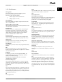
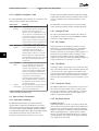
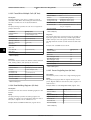
2.7.2 The Clear Advantage - Energy Savings
PRESSURE%
An extra protection in such areas is a coating of the
printed circuit boards, which can be ordered as an option.
120
100
INPUT POWER %
2 2
VLT® Micro Drive FC 51 Design Guide
Safety and Conformity
80
60
40
20
0
ENERGY
CONSUMED
20
40
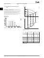
Illustration 2.2 When using a frequency converter to reduce
fan capacity to 60% - more than 50% energy savings may be
obtained in typical applications.
12
MG02K302 - Rev. 2013-12-03
VLT® Micro Drive FC 51 Design Guide
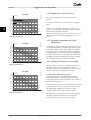
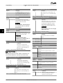
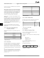
2.7.3 Example of Energy Savings
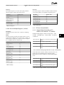
As shown in Illustration 2.3, the flow is controlled by
changing the RPM. By reducing the speed only 20% from
the rated speed, the flow is also reduced by 20%. This is
because the flow is directly proportional to the RPM. The
consumption of electricity, however, is reduced by 50%.
If the system in question only needs to be able to supply a
flow that corresponds to 100% a few days in a year, while
the average is below 80% of the rated flow for the
remainder of the year, the amount of energy saved is even
more than 50%.
Discharge
damper
Less energy savings
175HA208.10
Illustration 2.3 describes the dependence of flow, pressure
and power consumption on RPM.
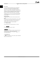
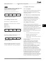
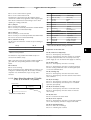
Illustration 2.5 shows typical energy savings obtainable
with 3 well-known solutions when fan volume is reduced
to i.e. 60%.
As the graph shows, more than 50% energy savings can be
achieved in typical applications.
130BA782.10
Safety and Conformity
100%
80%
50%
Maximum energy savings
Flow ~n
Pressure ~n2
IGV
25%
Power ~n3
12,5%
Costlier installation
n
50%
Illustration 2.4 The 3 Common Energy Saving Systems
80% 100%
130BA779.11
Illustration 2.3 Laws of Proportionally
100
Q1
n1
Flow :
=
Q2
n2
H1
n1 2
Pressure :
=
H2
n2
P1
n1 3
Power :
=
P2
n2
IGV Solution
80
P1=Rated power
Q2=Reduced flow
P2=Reduced power
H=Pressure
n=Speed regulation
H1=Rated pressure
n1=Rated speed
H2=Reduced pressure
n2=Reduced speed
40
20
Energy consumed
Q1=Rated flow
60
Energy consumed
P=Power
VLT Solution
Energy consumed
Input power %
Q=Flow
Discharge Damper Solution
Table 2.4 The Laws of Proportionality
0
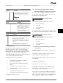
2.7.4 Comparison of Energy Savings
0
60
0
60
0
60
Volume %
The Danfoss frequency converter solution offers major
savings compared with traditional energy saving solutions.
This is because the frequency converter is able to control
fan speed according to thermal load on the system and
the fact that the frequency converter has a built-in facility
that enables the frequency converter to function as a
Building Management System, BMS.
Illustration 2.5 Energy Savings
Discharge dampers reduce power consumption. Inlet Guide
Vans offer a 40% reduction, but are expensive to install.
The Danfoss frequency converter solution reduces energy
consumption with more than 50% and is easy to install.
MG02K302 - Rev. 2013-12-03
13
2 2
VLT® Micro Drive FC 51 Design Guide
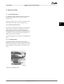
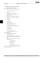
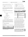
2.7.5 Example with Varying Flow over 1
Year
Hs
(mwg)
175HA209.11
2 2
Safety and Conformity
60
This example is calculated based on pump characteristics
obtained from a pump datasheet.
The result obtained shows energy savings in excess of 50%
at the given flow distribution over a year. The pay back
period depends on the price per kWh and price of
frequency converter. In this example it is less than a year
when compared with valves and constant speed.
50
B
40
30
A
20
1650rpm
1350rpm
C
10
1050rpm
750rpm
Energy savings
Pshaft=Pshaft output
0
100
200
300
400
(m3 /h)
Pshaft
(kW)
60
50
A1
40
1650rpm
30
1350rpm
B1
20
10
C1
Illustration 2.6 Flow Distribution over 1 Year
0
1050rpm
750rpm
100
200
400 (m3 /h)
300
Illustration 2.7 Energy
m3/
h
Distribution
%
Hours
350
5
438
300
15
250
20
200
Power
A1 - B1
kWh
A1 - C1
kWh
42.5
18.615
42.5
18.615
1314
38.5
50.589
29.0
38.106
1752
35.0
61.320
18.5
32.412
20
1752
31.5
55.188
11.5
20.148
150
20
1752
28.0
49.056
6.5
11.388
100
20
1752
23.0
40.296
3.5
100 8760
Table 2.5 Result
MG02K302 - Rev. 2013-12-03
Power
Frequency converter
control
Consumption
Σ
14
Valve regulation
275.064
Consumption
6.132
26.801
VLT® Micro Drive FC 51 Design Guide
Safety and Conformity
2.7.8 Using a Frequency Converter Saves
Money
2.7.6 Better Control
If a frequency converter is used for controlling the flow or
pressure of a system, improved control is obtained.
A frequency converter can vary the speed of the fan or
pump, obtaining variable control of flow and pressure.
Furthermore, a frequency converter can quickly adapt the
speed of the fan or pump to new flow or pressure
conditions in the system.
Simple control of process (Flow, Level or Pressure) utilising
the built-in PI control.
Example chapter 2.7.9 Without a Frequency Converter shows
that a lot of equipment is not required when a frequency
converter is used. It is possible to calculate the cost of
installing the 2 different systems. In the example, the 2
systems can be established at roughly the same price.
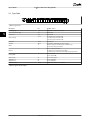
2.7.7 Star/Delta Starter or Soft-starter not
Required
When larger motors are started, it is necessary in many
countries to use equipment that limits the start-up current.
In more traditional systems, a star/delta starter or softstarter is widely used. Such motor starters are not required
if a frequency converter is used.
As illustrated in Illustration 2.8, a frequency converter does
not consume more than rated current.
175HA227.10
800
700
600
% Full load current
4
500
400
300
3
200
2
100
0
1
0
12,5
25
37,5
50Hz
Full load
& speed
1
VLT® Micro Drive
2
Star/delta starter
3
Soft-starter
4
Start directly on mains
Illustration 2.8 Current
MG02K302 - Rev. 2013-12-03
15
2 2
VLT® Micro Drive FC 51 Design Guide
Safety and Conformity
2.7.9 Without a Frequency Converter
Cooling section
Heating section
-
Return
Control
Flow
3-Port
valve
Valve
position
Bypass
Fan section
Supply
air
Fan
M
+
Flow
3-Port
valve
Return
Inlet guide vane
Bypass
V.A.V
Sensors
PT
outlets
Control
Mechanical
linkage
and vanes
Valve
position
x6
Pump
M
Pump
M
x6
x6
Starter
Starter
IGV
Motor
or
actuator
Duct
Control
Starter
Main
B.M.S
Fuses
Fuses
LV
supply
P.F.C
LV
supply
P.F.C
Mains
Mains
D.D.C.
Direct Digital Control
E.M.S.
Energy Management system
V.A.V.
Variable Air Volume
Sensor P
Pressure
Sensor T
Temperature
Power
Factor
Correction
Mains
Table 2.6 Abbreviations used in Illustration 2.9
Illustration 2.9 Traditional Fan System
16
Local
D.D.C.
control
MG02K302 - Rev. 2013-12-03
Pressure
control
signal
0/10V
Temperature
control
signal
0/10V
175HA205.12
2 2
VLT® Micro Drive FC 51 Design Guide
Safety and Conformity
2.7.10 With a Frequency Converter
Heating section
Fan section
-
+
Fan
M
Return
Flow
Supply
air
V.A.V
outlets
Sensors
PT
Flow
Return
2 2
175HA206.11
Cooling section
x3
M
Pump
x3
M
VLT
VLT
Duct
Pump
x3
Control
temperature
0-10V
or
Mains 0/4-20mA Mains
VLT
Control
temperature
0-10V
or
0/4-20mA
Mains
Pressure
control
0-10V
or
0/4-20mA
D.D.C.
Direct Digital Control
E.M.S.
Energy Management system
V.A.V.
Variable Air Volume
Sensor P
Pressure
Sensor T
Temperature
Local
D.D.C.
control
Main
B.M.S
Table 2.7 Abbreviations used in Illustration 2.10
Illustration 2.10 Fan System Controlled by Frequency
Converters
MG02K302 - Rev. 2013-12-03
17
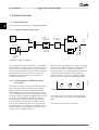
3 Product Overview
3.1 Control Structures
Select open loop or closed loop in 1-00 Configuration Mode.
100%
Reference
handling
Remote
reference
Auto mode
Hand mode
130BB892.10
3.1.1 Control Structure Open Loop
P 4-14
Motor speed
high limit [Hz]
P 3-4* Ramp 1
P 3-5* Ramp 2
0%
Remote
Reference
To motor
control
Ramp
Local
Local
reference
scaled to
Hz
100%
P 4-12
Motor speed
low limit [Hz]
-100%
LCP Hand on,
off and auto
on keys
P 4-10
Motor speed
direction
Illustration 3.1 Open Loop Structure
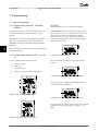
In the configuration shown in Illustration 3.1, 1-00 Configuration Mode is set to [0] Open loop. The resulting reference
from the reference handling system or the local reference
is received and fed through the ramp limitation and speed
limitation before being sent to the motor control. The
output from the motor control is then limited by the
maximum frequency limit.
After pressing the [Auto On] key, the frequency converter
goes into auto mode and follows (as default) the remote
reference. In this mode, it is possible to control the
frequency converter via the digital inputs and RS-485. See
more about starting, stopping, changing ramps and
parameter set-ups etc. in parameter group 5-1* Digital
Inputs or parameter group 8-5* Serial Communication.
3.1.2 Local (Hand On) and Remote (Auto
On) Control
The frequency converter can be operated manually via the
local control panel (LCP) or remotely via analog/digital
inputs or serial bus. If allowed in 0-40 [Hand on] Key on
LCP, 0-44 [Off/Reset] Key on LCP, and 0-42 [Auto on] Key on
LCP, it is possible to start and stop the frequency converter
by LCP pressing the [Hand On] and [Off/Reset] keys. Alarms
can be reset via the [Off/Reset] key. After pressing the
[Hand On] key, the frequency converter goes into hand
mode and follows (as default) the local reference set by
using the LCP potentiometer (LCP 12) or [▲]/[▼] (LCP 11).
The potentiometer can be disabled by parameter 6-80 LCP
Potmeter Enable. If the potentiometer is disabled, use the
navigation keys for adjusting reference.
18
Hand
On
Off
Reset
Auto
On
Illustration 3.2 LCP Control Keys
Local reference forces the configuration mode to open
loop, independent on the setting of 1-00 Configuration
Mode.
Local reference is restored at power-down.
MG02K302 - Rev. 2013-12-03
130BB893.10
3 3
VLT® Micro Drive FC 51 Design Guide
Product Overview
VLT® Micro Drive FC 51 Design Guide
Product Overview
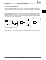
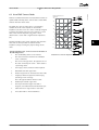
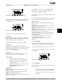
3.1.3 Control Structure Closed Loop
The internal controller allows the frequency converter to become an integral part of the controlled system. The frequency
converter receives a feedback signal from a sensor in the system. It then compares this feedback to a set-point reference
value and determines the error, if any, between these 2 signals. It then adjusts the speed of the motor to correct this error.
130BB894.11
For example, consider a pump application where the speed of a pump is to be controlled so that the static pressure in a
pipe is constant. The desired static pressure value is supplied to the frequency converter as the set-point reference. A static
pressure sensor measures the actual static pressure in the pipe and supplies this to the frequency converter as a feedback
signal. If the feedback signal is greater than the set-point reference, the frequency converter slows down to reduce the
pressure. In a similar way, if the pipe pressure is lower than the set-point reference, the frequency converter automatically
speed up to increase the pressure provided by the pump.
100%
Reference
+
0%
S
_
Scale to
speed
PI
*[-1]
To motor
control
100%
Feedback
7-30 PI
Normal/Inverse
Control
-100%
P 4-10
Motor speed
direction
Illustration 3.3 Control Structure Closed Loop
While the default values for the frequency converter’s closed loop controller often provides satisfactory performance, the
control of the system can often be optimised by adjusting some of the closed loop controller’s parameters.
MG02K302 - Rev. 2013-12-03
19
3 3
VLT® Micro Drive FC 51 Design Guide
Product Overview
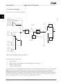
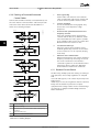
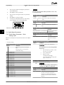
3.1.4 Reference Handling
Details for open loop and closed loop operation.
3 3
Intern resource
130BB900.13
Relative scalling reference
Preset relative reference
±100%
Preset reference 0 ±100%
Preset reference 1 ±100%
Preset reference 2 ±100%
Preset reference 3 ±100%
Preset reference 4 ±100%
Preset reference 5 ±100%
Preset reference 6 ±100%
Preset reference 7 ±100%
Input command:
preset ref bit0, bit1, bit2
Speed open
loop
Preset reference
Input command:
freeze reference
±100%
Y
Extern resource 1
Parameter choise:
Reference resource 1,2,3
No function
Configuration
mode
+
Analog reference
±200 %
X
Relative
reference
=
X+X*Y/100
Remote
reference/
setpoint
maxRefPCT
±200%
minRefPct
±200%
min-max ref
Process
control
±100%
Local bus reference
±200 %
LCP potmeter 0~100 %
Freeze
reference &
increase/
decrease
reference
+
Scale to
process
unit
Input commands:
±200%
Speed up/speed down
Extern resource 2
±200%
No function
Feedback
handling
Analog reference
±200 %
Local bus reference
±200 %
LCP potmeter 0~100 %
Scale to
Hz
External reference in %
Remote
reference in %
Extern resource 3
No function
Analog reference
±200 %
Local bus reference
±200 %
LCP potmeter 0~100 %
Illustration 3.4 Block Diagram Showing Remote Reference
The remote reference is comprised of:
•
•
•
•
Preset references
External references (analog inputs and serial communication bus references)
The preset relative reference
Feedback controlled setpoint
Up to 8 preset references can be programmed in the frequency converter. The active preset reference can be selected using
digital inputs or the serial communications bus. The reference can also be supplied externally, most commonly from an
analog input. This external source is selected by one of the 3 Reference Source parameters (3-15 Reference 1 Source,
3-16 Reference 2 Source and 3-17 Reference 3 Source). All reference resources and the bus reference are added to produce the
total external reference. The external reference, the preset reference or the sum of the 2 can be selected to be the active
reference. Finally, this reference can by be scaled using 3-14 Preset Relative Reference.
20
MG02K302 - Rev. 2013-12-03
VLT® Micro Drive FC 51 Design Guide
Product Overview
The scaled reference is calculated as follows:
Reference = X + X ×
Y
100
Where X is the external reference, the preset reference or the sum of these and Y is 3-14 Preset Relative Reference in [%].
If Y, 3-14 Preset Relative Reference, is set to 0%, the reference is not affected by the scaling.
3 3
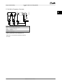
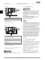
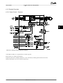
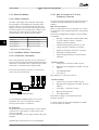
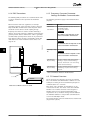
3.2 General Aspects of EMC
Electrical interference is usually conducted at frequencies in the range 150 kHz to 30 MHz. Airborne interference from the
frequency converter system in the range 30 MHz to 1 GHz is generated from the inverter, motor cable, and the motor.
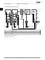
As shown in Illustration 3.5, capacitance in the motor cable coupled with a high dU/dt from the motor voltage generate
leakage currents.
The use of a screened motor cable increases the leakage current (see Illustration 3.5) because screened cables have higher
capacitance to ground than unscreened cables. If the leakage current is not filtered, it causes greater interference on the
mains in the radio frequency range below approximately 5 MHz. Since the leakage current (I1) is carried back to the unit
through the screen (I3), there is in principle only a small electro-magnetic field (I4) from the screened motor cable according
to Illustration 3.5.
CS
z
L1
z
L2
V
z
L3
W
z PE
PE
CS
U
I1
I2
CS
I3
1
2
CS
CS
I4
3
175ZA062.12
The screen reduces the radiated interference, but increases the low-frequency interference on the mains. Connect the motor
cable screen to the frequency converter enclosure as well as on the motor enclosure. This is best done by using integrated
screen clamps so as to avoid twisted screen ends (pigtails). Pigtails increase the screen impedance at higher frequencies,
which reduces the screen effect and increases the leakage current (I4).
If a screened cable is used for relay, control cable, signal interface and brake, mount the screen on the enclosure at both
ends. In some situations, however, it is necessary to break the screen to avoid current loops.
CS
I4
5
4
1
Ground wire
4
Frequency converter
2
Screen
5
Screened motor cable
3
AC mains supply
6
Motor
6
Illustration 3.5 Situation that Generates Leakage Currents
If the screen is to be placed on a mounting plate for the frequency converter, the mounting plate must be made of metal,
to convey the screen currents back to the unit. Moreover, ensure good electrical contact from the mounting plate through
the mounting screws to the frequency converter chassis.
When unscreened cables are used, some emission requirements are not complied with, although most immunity
requirements are observed.
MG02K302 - Rev. 2013-12-03
21
3 3
Product Overview
VLT® Micro Drive FC 51 Design Guide
To reduce the interference level from the entire system (unit+installation), make motor and brake cables as short as
possible. Avoid placing cables with a sensitive signal level alongside motor and brake cables. Radio interference higher than
50 MHz (airborne) is especially generated by the control electronics.
3.2.1 Emission Requirements
The EMC product standard for frequency converters
defines 4 categories (C1, C2, C3 and C4) with specified
requirements for emission and immunity. Table 3.1 states
the definition of the 4 categories and the equivalent classification from EN 55011.
Category Definition
Equivalent
emission
class in EN
55011
C1
Frequency converters installed in
the first environment (home and
office) with a supply voltage less
than 1000 V.
Class B
C2
Frequency converters installed in
the first environment (home and
office) with a supply voltage less
than 1000 V, which are neither
plug-in nor movable and are
intended to be installed and
commissioned by a professional.
Class A Group 1
C3
Frequency converters installed in
the second environment
(industrial) with a supply voltage
lower than 1000 V.
Class A Group 2
C4
Frequency converters installed in
the second environment with a
supply voltage equal to or above
1000 V or rated current equal to or
above 400 A or intended for use in
complex systems.
No limit line.
An EMC plan
should be
made.
When the generic (conducted) emission standards are
used, the frequency converters are required to comply
with the limits in Table 3.2.
Generic emission
standard
First
environment
(home and
office)
EN/IEC 61000-6-3 Emission
standard for residential,
commercial and light
industrial environments.
Class B
Second
environment
(industrial
environment)
EN/IEC 61000-6-4 Emission
standard for industrial
environments.
Class A Group 1
Table 3.2 Correlation between Generic Emission Standards and
EN 55011
Table 3.1 Correlation between IEC 61800-3 and EN 55011
22
Equivalent
emission class
in EN 55011
Environment
MG02K302 - Rev. 2013-12-03
VLT® Micro Drive FC 51 Design Guide
Product Overview
3.2.2 EMC Test Results (Emission)
Drive type
Conducted emission. Maximum shielded cable length [m]
Industrial environment
EN 55011 Class A2
Radiated emission
Housing, trades and
light industries
EN 55011 Class A1
EN 55011 Class B
Industrial environment
EN 55011 Class A2
EN 55011 Class A1
Without
external
filter
With
external
filter
Without
external
filter
With
external
filter
Without
external
filter
With
external
filter
Without
external
filter
With
external
filter
Without
external
filter
With
external
filter
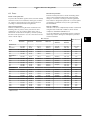
≤2.2 kW.
Single
phase, 230 V
25
-
15
50
5
15
Yes
-
No
Yes
≤7.5 kW. Up
to 500 V AC,
3 phase
25
-
15
50
-
15
Yes
-
No
Yes
11 kW to 22
kW. Up to
500 V AC, 3
phase
25
-
15
50
-
15
Yes
-
No
Yes
Table 3.3 EMC Test Result
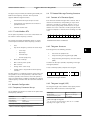
3.2.3 Harmonics Emission Requirements
Equipment connected to the public supply network
WARNING
3.3 Galvanic Isolation (PELV)
Cannot comply, only with power option
3.3.1 PELV - Protective Extra Low Voltage
PELV offers protection by way of extra low voltage.
Protection against electric shock is ensured when the
electrical supply is of the PELV type and the installation is
made as described in local/national regulations on PELV
supplies.
Options
Definition
1
IEC/EN 61000-3-2 Class A for 3-phase balanced
equipment (for professional equipment only up to 1
kW total power).
2
IEC/EN 61000-3-12 Equipment 16 A-75 A and professional equipment as from 1 kW up to 16 A phase
current.
Table 3.4 Harmonics Emission Requirements
3.2.4 Immunity Requirements
The immunity requirements for frequency converters
depend on the environment where they are installed. The
requirements for the industrial environment are higher
than the requirements for the home and office
environment. All Danfoss frequency converters comply
with the requirements for the industrial environment and
consequently comply also with the lower requirements for
home and office environment with a large safety margin.
All control terminals and relay terminals 01-03/04-06
comply with PELV (Protective Extra Low Voltage) (Does not
apply to grounded Delta leg above 440 V).
Galvanic (ensured) isolation is obtained by fulfilling
requirements for higher isolation and by providing the
relevant creapage/clearance distances. These requirements
are described in the EN 61800-5-1 standard.
The components that make up the electrical isolation, as
described, also comply with the requirements for higher
isolation and the relevant test as described in EN
61800-5-1.
The PELV galvanic isolation can be shown in Illustration 3.7.
To maintain PELV all connections made to the control
terminals must be PELV, e.g. thermistor must be
reinforced/double insulated.
MG02K302 - Rev. 2013-12-03
23
3 3
VLT® Micro Drive FC 51 Design Guide
Product Overview
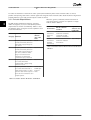
3.4 Earth Leakage Current
SMPS
3 3
M
130BB896.10
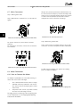
0.25-22 kW
DISCHARGE TIME
Touching the electrical parts could be fatal - even after
the equipment has been disconnected from mains.
Also make sure that other voltage inputs have been
disconnected, such as load sharing (linkage of DC
intermediate circuit), as well as the motor connection for
kinetic back-up.
Before touching any electrical parts, wait at least the
amount of time indicated in Table 2.1.
Shorter time is allowed only if indicated on the
nameplate for the specific unit.
1
2
WARNING
3
a
1 Power supply (SMPS)
2 Optocouplers, communication between AOC and BOC
NOTICE
3 Custom relays
a Control card terminals
Illustration 3.6 Galvanic Isolation
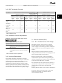
3
M
5
4
1
130BB901.10
30-90 kW
2
a
1 Power supply (SMPS) incl. signal isolation of UDC, indicating
the intermediate current voltage
2 Gate drive that runs the IGBTs (trigger transformers/optocouplers)
3 Current transducers
4 Internal soft-charge, RFI and temperature measurement
circuits
5 Custom relays
a Control card terminals
Illustration 3.7 Galvanic Isolation
The functional galvanic isolation (see Illustration 3.6) is for
the RS-485 standard bus interface.
CAUTION
Installation at high altitude:
At altitudes above 2,000 m, contact Danfoss regarding
PELV.
24
Leakage Current
The earth leakage current from the frequency converter
exceeds 3.5 mA. To ensure that the ground cable has a
good mechanical connection to the ground connection,
the cable cross section must be at least 10 mm2 Cu or 16
mm2 Al or 2 rated earth wires terminated separately.
Residual Current Device protection RCD
This product can cause a DC current in the protective
conductor. Where a residual current device (RCD) is used
for protection in case of direct or indirect contact, only
an RCD of Type B is allowed on the supply side of this
product. Otherwise, another protective measure shall be
applied, such as separation from the environment by
double or reinforced insulation, or isolation from the
supply system by a transformer. See also Application
Note Protection against Electrical Hazards, MN90G.
Protective earthing of the frequency converter and the
use of RCDs must always follow national and local
regulations.
3.5 Extreme Running Conditions
Short circuit (motor phase – phase)
Current measurement in each of the 3 motor phases or in
the DC-link, protects the frequency converter against short
circuts. A short circuit between 2 output phases causes an
overcurrent in the inverter. The inverter is turned off
individually when the short circuit current exceeds the
permitted value (Alarm 16 Trip Lock).
For information about protecting the frequency converter
against a short circuit at the load sharing and brake
outputs, see the design guidelines.
Switching on the output
Switching on the output between the motor and the
frequency converter is fully permitted. The frequency
converter is not damaged in any way by switching on the
output. However, fault messages may appear.
MG02K302 - Rev. 2013-12-03
VLT® Micro Drive FC 51 Design Guide
Motor-generated over-voltage
The voltage in the intermediate circuit is increased when
the motor acts as a generator. This occurs in following
cases:
•
The load drives the motor (at constant output
frequency from the frequency converter), that is
the load generates energy.
•
During deceleration ("ramp-down") if the moment
of inertia is high, the friction is low and the rampdown time is too short for the energy to be
dissipated as a loss in the frequency converter,
the motor and the installation.
•
Incorrect slip compensation setting (1-62 Slip
Compensation) may cause higher DC link voltage.
The control unit may attempt to correct the ramp if
possible (2-17 Over-voltage Control.)
The inverter turns off to protect the transistors and the
intermediate circuit capacitors when a certain voltage level
is reached.
Mains drop-out
During a mains drop-out, the frequency converter keeps
running until the intermediate circuit voltage drops below
the minimum stop level, which is typically 15% below the
frequency converter's lowest rated supply voltage. The
mains voltage before the drop-out and the motor load
determines how long it takes for the frequency converter
to coast.
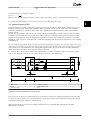
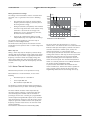
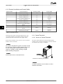
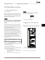
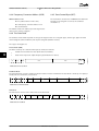
3.5.1 Motor Thermal Protection
Motor thermal protection can be provided in 2 ways.
175ZA052.12
Product Overview
t [s]
2000
1000
600
500
400
300
200
100
60
50
40
30
20
10
3 3
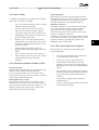
fOUT = 1 x f M,N(par. 1-23)
fOUT = 2 x f M,N
fOUT = 0.2 x f M,N
1.0 1.2 1.4 1.6 1.8 2.0
IM
IMN(par. 1-24)
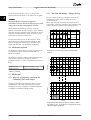
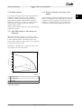
Illustration 3.8 ETR Characteristics
The X-axis shows the ratio between Imotor and Imotor
nominal. The Y- axis shows the time in seconds before the
ETR cut of and trips the frequency converter. The curves
show the characteristic nominal speed, at twice the
nominal speed and at 0,2 x the nominal speed.
At lower speed, the ETR cuts off at lower heat due to less
cooling of the motor. In that way, the motor is protected
from being over heated even at low speed. The ETR
feature is calculating the motor temperature based on
actual current and speed. The calculated temperature is
visible as a read out parameter in 16-18 Motor Thermal in
the product specific Programming Guide.
A special version of the ETR is also available for EX-e
motors in ATEX areas. This function makes it possible to
enter a specific curve to protect the Ex-e motor. The
Programming Guide takes the user through the set-up.
One method uses a motor thermistor, via one of the
following
•
•
•
Thermistor input on a standard AI
Sensor input MCB 114
PTC Thermistor input MCB 112
The frequency converter monitors motor temperature as
the speed and load vary to detect overheating conditions.
The other method calculates motor temperature by
measuring current, frequency, and operating time. The
converter displays the thermal load on the motor in
percentage and can issue a warning at a programmable
overload setpoint. Programmable options at the overload
allow the frequency converter to stop the motor, reduce
output, or ignore the condition. Even at low speeds, the
frequency converter meets I2t Class 20 electronic motor
overload standards.
This method is called Electronic Thermal Relay (ETR).
MG02K302 - Rev. 2013-12-03
25
4 4
Selection
VLT® Micro Drive FC 51 Design Guide
4 Selection
4.1 Options and Accessories
4.1.1 Local Control Panel (LCP)
For detailed information on programming, see VLT® Micro
Drive FC 51Programming Guide.
NOTICE
The frequency converter can also be programmed from a
PC via RS-485 com-port by installing the MCT 10 Set-up
Software.
This software can either be ordered using code number
130B1000 or downloaded from the DanfossWeb site:
www.danfoss.com/BusinessAreas/DrivesSolutions/softwaredownload
Navigation Keys:
[Back]: For moving to the previous step or layer in the
navigation structure.
[▲] [▼]: For maneuvering between parameter groups,
parameters and within parameters.
[OK]: For selecting a parameter and for accepting changes
to parameter settings.
Operation Keys:
A yellow light above the operation keys indicates the
active key.
[Hand On]: Starts the motor and enables control of the
frequency converter via the LCP.
[Off/Reset]: Stops the motor (off). If in alarm mode the
alarm is reset.
[Auto On]: The frequency converter is controlled either via
control terminals or serial communication.
[Potentiometer] (LCP 12): The potentiometer works in 2
ways depending on the mode in which the frequency
converter is running.
In Auto Mode the potentiometer acts as an extra
programmable analog input.
In Hand on Mode the potentiometer controls local
reference.
4.1.2 Remote Mounting Kit for LCP
The LCP can be moved to the front of a cabinet by using
the remote built-in kit. The enclosure is IP55.
Illustration 4.1 Description of LCP Keys and Display
Enclosure
Max. cable length between LCP and unit:
Press [Menu] to select one of the following menus:
Communication std:
Ordering no.
Status:
For readouts only.
Table 4.1 Technical Data
Quick Menu:
For access to Quick Menus 1 and 2.
Main Menu:
For access to all parameters.
26
MG02K302 - Rev. 2013-12-03
IP55 front
3m
RS-485
132B0102
Selection
VLT® Micro Drive FC 51 Design Guide
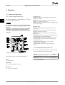
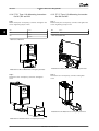
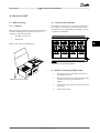
4.1.3 FC 51 LCP Mounting Instruction
Step 1
Fit gasket on LCP in the frequency converter.
130BA526.10
Step 1
Place the bottom of the LCP in the frequency converter.
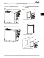
4.1.4 FC 51 Remote Mounting Kit Mounting
Instruction
4 4
Illustration 4.4 Fit Gasket on LCP
62.3±0.2
130BA568.10
Illustration 4.2 Place the LCP in the Frequency Converter
Step 2
Place LCP on panel - see dimensions of hole on drawing.
82.8±0.2
Step 2
Push the top of the LCP into the frequency converter.
4xR 1.5±0.5
1
130BA527.10
Illustration 4.5 Dimensions of Hole
1
2
3
Illustration 4.3 Push the Top of the LCP into Place
Illustration 4.6 Panel, Gasket and LCP
MG02K302 - Rev. 2013-12-03
27
Selection
VLT® Micro Drive FC 51 Design Guide
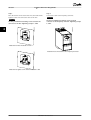
Step 3
Place the bracket on the back of the LCP, then slide down.
Tighten screws and connect the cable to the LCP.
NOTICE
NOTICE
Use the provided thread cutting screws to fasten
connector to the frequency converter. Tightening torque:
1.3 Nm.
4 4
130BA525.10
130BA523.10
Use the provided thread cutting screws to fasten the
connector to the LCP. Tightening torque: 1.3 Nm.
Step 4
Connect the cable to the frequency converter.
Illustration 4.7 Place the Bracket on LCP
130BA524.10
Illustration 4.9 Connect Cable to the Frequency Converter
Illustration 4.8 Tighten Screws and Connect Cable to LCP
28
MG02K302 - Rev. 2013-12-03
VLT® Micro Drive FC 51 Design Guide
Selection
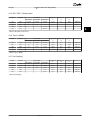
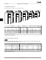
4.1.5 IP21/TYPE 1 Enclosure Kit
Frame
IP class
3x200-240 V
3x380-480 V
Height [mm]
A
Width [mm]
B
Depth [mm]
C
Ordering no.
1x200-240 V
Power [kW]
M1
IP21
0.18-0.75
0.25-0.75
0.37-0.75
219.3
73
155.9
132B0108
M2
IP21
1.5
1.5
1.5-2.2
245.6
78
175.4
132B0109
M3
IP21
2.2
2.2-3.7
3.0-7.5
297.5
95
201.4
132B0110
M4
IP21
-
-
11-15
-
-
-
-
M5
IP21
-
-
18.5-22
-
-
-
-
3x200-240 V
3x380-480 V
Height [mm]
A
Width [mm]
B
Depth [mm]
C
Ordering no.
1x200-240 V
4 4
Table 4.2 IP21/TYPE 1 Enclosure Kit
4.1.6 Type 1 (NEMA)
Frame
IP class
Power [kW]
M1
IP20
0.18-0.75
0.25-0.75
0.37-0.75
194.3
70.0
155.9
132B0103
M2
IP20
1.5
1.5
1.5-2.2
220.6
75.0
175.4
132B0104
M3
IP20
2.2
2.2-3.7
3.0-7.5
282.5
90.0
201.3
132B0105
M4
IP20
-
-
11-15
345.6
125.0
248.5
132B0120
M5
IP20
-
-
18.5-22
385.5
165.0
248.2
132B0121
3x200-240 V
3x380-480 V
Height [mm]
A
Width [mm]
B
Depth [mm]
C
Ordering no.
1x200-240 V
Table 4.3 Type 1 (NEMA)
4.1.7 De-Coupling
Frame
IP class
Power [kW]
M1
IP20
0.18-0.75
0.25-0.75
0.37-0.75
204.2
70.0
155.9
132B0106
M2
IP20
1.5
1.5
1.5-2.2
230.0
75.0
175.4
132B0106
M3
IP20
2.2
2.2-3.7
3.0-7.5
218.5
90.0
201.3
132B0107
M4
IP20
-
-
11-15
347.5
125.0
248.5
132B0122
M5
IP20
-
-
18.5-22
387.5
165.0
248.2
132B0122
Table 4.4 De-Coupling
MG02K302 - Rev. 2013-12-03
29
4 4
VLT® Micro Drive FC 51 Design Guide
Selection
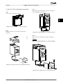
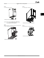
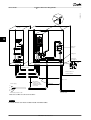
4.1.8 FC 51 Type 1 Kit Mounting Instruction
for M1, M2 and M3
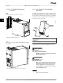
4.1.9 FC 51 Type 1 Kit Mounting Instruction
for M4 and M5
Step 1
Mount metal plate on frequency converter and tighten the
screws. Tightening torque: 2 Nm.
Step 1
Mount metal plate on frequency converter and tighten the
screws. Tightening torque: 2 Nm.
M1
4 x ½”
M4
3x½”
M2
5x½“
M5
3x1“
M3
2 x ½”
Table 4.6 Conduit Sizes
3 x 3/4”
Table 4.5 Conduit Sizes
Illustration 4.10 Mount Metal Plate on Frequency Converter
Step 2
Fit bottom cover on frequency converter and tighten
screw.
Illustration 4.12 Mount Metal Plate on Frequency Converter
Step 2
Fit bottom cover on frequency converter and tighten
screw.
Illustration 4.13 Fit Bottom Cover on Frequency Converter
Illustration 4.11 Fit Bottom Cover on Frequency Converter
30
MG02K302 - Rev. 2013-12-03
Selection
VLT® Micro Drive FC 51 Design Guide
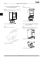
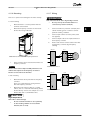
4.1.10 FC 51 IP21 Kit Mounting Instruction
Step 1
Fit top cover on frequency converter.
Step 3
Mount metal plate on frequency converter and tighten
screws. Tightening torque: 2 Nm.
4 4
Illustration 4.14 Fit Top Cover on Frequency Converter
Step 2
Remove knock-outs on metal plate and fit rubber
grommets.
130BC014.10
Illustration 4.16 Mount Metal Plate on Frequency Converter
Step 4
Fit bottom cover on frequency converter and tighten
screw.
NOTICE
IP21 is only achieved with LCP 11 or LCP 12 mounted.
Illustration 4.15 Remove Knock-outs and Fit Rubber Grommets
Illustration 4.17 Fit Bottom Cover on Frequency Converter
MG02K302 - Rev. 2013-12-03
31
Selection
VLT® Micro Drive FC 51 Design Guide
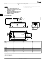
4.1.11 FC 51 De-coupling Plate Mounting
Instruction for M1 and M2
Step 3
De-coupling plate mounted.
Step 1
Mount metal plate on frequency converter and fasten with
two screws. Tightening torque: 2 Nm.
4 4
Illustration 4.20 De-coupling Plate Mounted
Illustration 4.18 Mount Metal Plate
Step 2
Mount bracket on de-coupling plate.
4.1.12 FC 51 De-coupling Plate Mounting
Instruction for M3
Step 1
Mount de-coupling plate on frequency converter and
fasten with 2 screws. Tightening torque: 2 Nm.
Illustration 4.21 Mount De-coupling Plate
Illustration 4.19 Mount Bracket
Illustration 4.22 Fasten with Screws
32
MG02K302 - Rev. 2013-12-03
Selection
VLT® Micro Drive FC 51 Design Guide
Step 2
De-coupling plate mounted.
Step 2
De-coupling plate mounted.
4 4
Illustration 4.23 De-coupling Plate Mounted
4.1.13 FC 51 De-coupling Plate Mounting
Instruction for M4 and M5
Step 1
Mount metal plate on frequency converter and fasten with
2 screws. Tightening torque: 2 Nm.
Illustration 4.25 De-coupling Plate Mounted
Step 3
Mount bracket on de-coupling plate.
Illustration 4.26 Mount Bracket
Illustration 4.24 Mount Metal Plate
MG02K302 - Rev. 2013-12-03
33
Selection
VLT® Micro Drive FC 51 Design Guide
4.1.14 FC 51 DIN Rail Kit Mounting
Instruction
4.1.15 Line Filter MCC 107 Installation
Instructions
Step 1
Mount plastic part on frequency converter.
Line filters of the type MCC 107 combine a harmonic filter
and an EMC filter. The line filters improve performance of
the line current to the frequency converter. The 3 different
line filter frame sizes correspond to the VLT® Micro Drive
enclosure types M1, M2 and M3.
130BC160.10
4 4
1
2
3
4
Illustration 4.27 Mount Plastic Part
1 Mounting holes for frequency converter
2 Input terminal
Step 2
Fit frequency converter on DIN rail (Din Rail kit is only for
M1 and M2).
3 Output line
4 Protective earth (PE)
Illustration 4.29 Line Filter MCC 107 with Micro Drive FC 51
CAUTION
Hot surfaces
Risk of high surface temperatures.
•
Do NOT touch the line filter during operation or
wear protective gloves
WARNING
High voltage
Risk of electric shock.
•
Never carry out maintenance work on the line
filter during operation. Wait at least 4 minutes
after the equipment has been disconnected
from the frequency converter before touching
any potentially live parts.
Illustration 4.28 Fit Frequency Converter on DIN Rail
NOTICE
•
34
Never repair a defective filter
MG02K302 - Rev. 2013-12-03
VLT® Micro Drive FC 51 Design Guide
Selection
4.1.16 Mounting
4.1.17 Wiring
There are 2 options for mounting the line filter correctly:
WARNING
Risk of electrical shock due to high leakage currents
Mount the filter in a vertical position with the
terminals at the bottom.
•
Mount the frequency converter on the front of
the line filter using 3 M4 bolts.
130BC159.10
•
•
Do not power up the line filter before it is
connected to protective earth (PE)
1.
Connect line filter to protective earth (PE). Use a
cabinet mounting panel or similar to achieve
optimum earthing conditions.
2.
Connect input terminal to mains power (cable
not supplied)
3.
Connect output cable to the input terminals of
the frequency converter
4.
Ensure solid electrical contact between line filter
and frequency converter (high frequency
earthing)
MCC 107
FC 51
PE
L
PE
U
U
V
V
M
3~
L
Illustration 4.30 Line Filter with Frequency Converter
Ensure metal-to-metal contact between filter and
frequency converter.
NOTICE
PE
Illustration 4.31 Line 1
Metal-to-metal contact improves EMC performance and
enables the baseplate of the frequency converter to
function as heat sink for the line filter
MCC 107
2. Side mounting
L1
•
•
W
W
N
Mount the filter side-by-side with the frequency
converter.
There is no requirement for spacing between
filter and frequency converter.
Mount the back of the line filter to a cooling
surface, such as a metal wall. Alternatively, derate
the line filter by one size: For example use a 0.75
kW line filter with a 0.37 kW Micro Drive.
L2
FC 51
PE
L1
L2
L3
L3
PE
U
U
V
V
W
130BC162.10
•
N
130BC161.10
1. Front mounting
M
3~
W
PE
Illustration 4.32 Line 2
CAUTION
High temperatures
Risk of fire or device damage
•
Do not mount the line filter in close proximity
to other heating elements or heat-sensitive
material (such as wood).
MG02K302 - Rev. 2013-12-03
35
4 4
NOTICE
•
Reduce common mode interferences by
establishing a low impedance current path to
the frequency converter.
•
To ensure optimum EMC performance, use a
De-Coupling plate kit (ordering numbers
132B0106 or 132B0107)
For voltage rating, wire size and fuse selection, see the
VLT® Micro Drive Quick Guide.
130BC163.10
4.1.18 Dimensions
M6
100
+10
0
+20
0
1
d
300
PE
W
h1
l1
h2
LOAD
7.8
h
Ø11
W2
l2
Ø5.5
W1
M4(3x)
l2
LINE
5.5
4 4
VLT® Micro Drive FC 51 Design Guide
Selection
h3
Frame
M1
M2
M3
w [mm]
70
75
90
d [mm]
55
65
69
h [mm]
190
210
300
h3 [mm]
230
250
340
w1 [mm]
40
40
55.6
h1 [mm]
213
233
323
w2 [mm]
55
59
69
h2 [mm]
140
166.5
226
l1 [mm]
45
38.5
68
l2 [mm]
7.6
8
9.3
PE (metric)
M6
M6
M6
Weight [kg]
2
3
5
Table 4.7 Dimension Data
Illustration 4.33 Dimensions
36
MG02K302 - Rev. 2013-12-03
VLT® Micro Drive FC 51 Design Guide
4.2 Special Conditions
M2 200 V
Iout [%]
4.2.1 Purpose of Derating
Take the purpose of derating into account when using the
frequency converter at low air pressure (heights), at low
speeds, with long motor cables, cables with a large cross
section or at high ambient temperature. The required
action is described in this section.
130BC030.10
Selection
110 %
100 %
90 %
80 %
70 %
60 %
50 %
40 %
4 4
40 ℃
30 %
20 %
4.2.2 Derating for Ambient Temperature
10 %
0
Derating for ambient temperature and IGBT Switching.
45 ℃
50 ℃
0
2
4
6
8
10
12
14
16 fsw [kHz]
Illustration 4.36 M2 200 V
130BC028.10
M1 200 V
Iout [%]
110 %
100 %
90 %
80 %
70 %
60 %
50 %
40 %
40 ℃
30 %
20 %
45 ℃
30 %
20 %
40 ℃
10 %
0
45 ℃
50 ℃
0
2
4
6
8
10
12
14
16 fsw [kHz]
Illustration 4.37 M2 400 V
0
2
4
6
8
10
12
14
50 ℃
16 fsw [kHz]
Iout [%]
130BC029.10
M1 400 V
110 %
100 %
90 %
80 %
70 %
60 %
50 %
40 %
M3 200 V
Iout [%]
Illustration 4.34 M1 200 V
110 %
100 %
90 %
80 %
70 %
60 %
50 %
40 %
40 ℃
30 %
20 %
10 %
0
50 ℃
0
2
4
6
8
10
12
14
45 ℃
16 fsw [kHz]
Illustration 4.38 M3 200 V
30 %
20 %
10 %
0
110 %
100 %
90 %
80 %
70 %
60 %
50 %
40 %
130BC032.10
10 %
0
M2 400 V
Iout [%]
130BC031.10
The ambient temperature measured over 24 hours should
be at least 5 °C lower than the max. ambient temperature.
If the frequency converter is operated at high ambient
temperature, the continuous output current should be
decreased. The frequency converter has been designed for
operation at max. 50 °C ambient temperature with one
motor size smaller than nominal. Continuous operation at
full load at 50 °C ambient temperature reduces the lifetime
of the frequency converter.
40 ℃
45 ℃
0
2
4
6
8
10
12
50 ℃
14
16 fsw [kHz]
Illustration 4.35 M1 400 V
MG02K302 - Rev. 2013-12-03
37
VLT® Micro Drive FC 51 Design Guide
Selection
Iout [%]
130BC033.10
M3 400 V
110 %
100 %
90 %
80 %
70 %
60 %
50 %
40 %
4 4
40 ℃
50 ℃
0
2
4
6
8
10
12
14
45 ℃
16 fsw [kHz]
Illustration 4.39 M3 400 V
130BC034.10
M4 400 V
Iout [%]
110 %
100 %
90 %
80 %
70 %
60 %
50 %
40 %
30 %
20 %
10 %
0
40 ℃
45 ℃
50 ℃
0
2
4
6
8
10
12
14
16 fsw [kHz]
Illustration 4.40 M4 200 V
130BC035.10
M5 400 V
Iout [%]
110 %
100 %
90 %
80 %
70 %
60 %
50 %
40 %
30 %
20 %
10 %
0
40 ℃
45 ℃
50 ℃
0
2
4
6
Illustration 4.41 M4 400 V
38
The cooling capability of air is decreased at low air
pressure.
For altitudes above 2,000 m, contact Danfoss regarding
PELV.
30 %
20 %
10 %
0
4.2.3 Derating for Low Air Pressure
8
10
12
14
16 fsw [kHz]
Below 1,000 m altitude no de-rating is necessary, but
above 1.000 m the ambient temperature or the maximum
output current should be decreased.
Decrease the output by 1% per 100 m altitude above 1,000
m or reduce the max. ambient temperature by 1 ° C per
200 m.
4.2.4 Automatic Adaptations to Ensure
Performance
The frequency converter constantly checks for critical levels
of internal temperature, load current, high voltage on the
intermediate circuit and low motor speeds. As a response
to a critical level, the frequency converter can adjust the
switching frequency and/or change the switching pattern
to ensure the performance of the frequency converter. The
capability for automatic output current reduction extends
the acceptable operating conditions even further.
4.2.5 Derating for Running at Low Speed
When a motor is connected to a frequency converter, it is
necessary to check that the cooling of the motor is
adequate. The level of heating depends on the load on the
motor, as well as the operating speed and time.
Constant torque applications (CT mode)
A problem may occur at low RPM values in constant
torque applications. In a constant torque application a
motor may over-heat at low speeds due to less cooling air
from the motor integral fan.
Therefore, if the motor is to be run continuously at an RPM
value lower than half of the rated value, the motor must
be supplied with additional air-cooling (or a motor
designed for this type of operation may be used).
An alternative is to reduce the load level of the motor by
choosing a larger motor. However, the design of the
frequency converter puts a limit to the motor size.
MG02K302 - Rev. 2013-12-03
How to Order
VLT® Micro Drive FC 51 Design Guide
5 How to Order
5.1 Drive Configurator
It is possible to design a frequency converter according to
the application requirements by using the ordering
number system.
Frequency converters can be ordered as standard or with
internal options by using a type code string, that is,
5 5
FC051PXXXXXXXXHXXXXXXXSXXX
Use the Internet-based Drive Configurator to configure the
right frequency converter for the right application and
generate the type code string. The Drive Configurator
automatically generates an 8-digit sales number (either for
one product or a project list with several products) to be
delivered to your local sales office.
The Drive Configurator can be found on: www.danfoss.com/
drives.
5.2 FC Identification
The nameplate sticker is located on the top of each
frequency converter and shows the ratings, serial number,
warnings catalog number, and other relevant data for each
unit. See Table 5.2 for details, how to read the type code
string.
Illustration 5.1 Nameplate Sticker
MG02K302 - Rev. 2013-12-03
39
5 5
How to Order
VLT® Micro Drive FC 51 Design Guide
5.3 Type Code
Table 5.1 Type Code
Description
Pos
Possible choice
Product group
1-3
Adjustable Frequency Converters
Series and product type
4-6
Micro Drive
Power size
7-10
0.18-22 kW
11-12
S2: Single phase 200-240 V AC
T 2: Three phase 200-240 V AC
T 4: Three phase 380-480 V AC
Enclosure
13-15
IP20/Chassis
RFI filter
16-17
H3: RFI filter A1/B (reduced cable length*)
18
B: Brake chopper included (from 1.5 kW and up)
X: No brake chopper included
19
X: No Local Control Panel
N: Numerical Local Control Panel (LCP)
P: Numerical Local Control Panel (LCP) with potentiometer
20
C: Coated PCB
X: No coated PCB
Mains option
21
X: No mains option
Adaptation A
22
X: No adaptation
Adaptation B
23
X: No adaptation
Software release
24-27
SXXX: Latest release - std. software
Mains voltage
Brake
Display
Coating PCB
Table 5.2 Type Code Description
40
MG02K302 - Rev. 2013-12-03
VLT® Micro Drive FC 51 Design Guide
How to Order
5.4 Ordering Numbers
200-240 V
Power [kW]
Current [lnom]
1 ph.
0.18
1.2
132F 0001
380-480 V
3 ph.
Current [lnom]
3 ph.
0.25
1.5
0.37
2.2
132F 0002
132F 0009
132F 0008
1.2
132F 0017
0.75
4.2
132F 0003
132F 0010
2.2
132F 0018
1.5
6.8
132F 0005
132F 0012
3.7
132F 0020
2.2
9.6
132F 0007
132F 0014
5.3
132F 0022
7.2
132F 0024
4.0
9.0
132F 0026
5.5
12.0
132F 0028
7.5
15.5
132F 0030
23.0
132F 0058
15.0
31.0
132F 0059
18.5
37.0
132F 0060
22.0
43.0
132F 0061
3.0
3.7
11.0
15.2
5 5
132F 0016
Micro drives from 1.5 kW and up have built in brake chopper
Table 5.3 Ordering Numbers
5.5 Options
Ordering No
Description
132B0100
VLT Control Panel LCP 11 w/o potentiometer
132B0101
VLT Control Panel LCP 12 w/o potentiometer
132B0102
Remote Mounting Kit for LCP incl. 3 m cable IP55 with LCP 11, IP21 with LCP 12
132B0103
Nema Type 1 kit for M1 frame
132B0104
Type 1 kit for M2 frame
132B0105
Type 1 kit for M3 frame
132B0106
De-coupling plate kit for M1 and M2 frames
132B0107
De-coupling plate kit for M3 frame
132B0108
IP21 for M1 frame
132B0109
IP21 for M2 frame
132B0110
IP21 for M3 frame
132B0111
DIN rail mounting kit for M1 and M2 frame
132B0120
Type 1 kit for M4 frame
132B0121
Type 1 kit for M5 frame
132B0122
De-coupling plate kit for M4 and M5 frames
130B2522
Line Filter MCC 107 for 132F0001
130B2522
Line Filter MCC 107 for 132F0002
130B2533
Line Filter MCC 107 for 132F0003
130B2525
Line Filter MCC 107 for 132F0005
130B2530
Line Filter MCC 107 for 132F0007
130B2523
Line Filter MCC 107 for 132F0008
130B2523
Line Filter MCC 107 for 132F0009
130B2523
Line Filter MCC 107 for 132F0010
130B2526
Line Filter MCC 107 for 132F0012
130B2531
Line Filter MCC 107 for 132F0014
130B2527
Line Filter MCC 107 for 132F0016
130B2523
Line Filter MCC 107 for 132F0017
130B2523
Line Filter MCC 107 for 132F0018
130B2524
Line Filter MCC 107 for 132F0020
MG02K302 - Rev. 2013-12-03
41
5 5
VLT® Micro Drive FC 51 Design Guide
How to Order
Ordering No
Description
130B2526
Line Filter MCC 107 for 132F0022
130B2529
Line Filter MCC 107 for 132F0024
130B2531
Line Filter MCC 107 for 132F0026
130B2528
Line Filter MCC 107 for 132F0028
130B2527
Line Filter MCC 107 for 132F0030
Table 5.4 Options for VLT Micro Drive
NOTICE
Danfoss line filters and brake resistors are available upon request.
42
MG02K302 - Rev. 2013-12-03
How to Install
VLT® Micro Drive FC 51 Design Guide
6 How to Install
6.1 Before Starting
6.2 Side-by-Side Installation
6.1.1 Checklist
The frequency converter can be mounted side-by-side for
IP 20 rating units and requires 100 mm clearance above
and below for cooling. Regarding surroundings in general,
see chapter 9 Specifications.
When unpacking the frequency converter, make sure that
the unit is undamaged and complete. Check that the
packaging contains the following:
•
•
VLT® Micro Drive FC 51
Quick Guide
6 6
Optional: LCP and/or de-coupling plate.
Illustration 6.2 Side-by-side Installation
6.3 Before Commencing Repair Work
Illustration 6.1 Content of Box
1.
Disconnect the FC 51 from mains (and external
DC supply, if present.)
2.
Wait for 4 min (M1, M2 and M3) and 15 min (M4
and M5) for discharge of the DC-link. See
Table 2.1.
3.
Disconnect DC bus terminals and brake terminals
(if present).
4.
Remove motor cable.
MG02K302 - Rev. 2013-12-03
43
VLT® Micro Drive FC 51 Design Guide
How to Install
6.4 Mechanical Dimensions
B
b
B
b
Ø 7mm
B
b
Ø 5.5mm
C
C
C
B
b
Ø 7mm
B
b
Ø 4.5mm
C
130BB321.11
A template for drilling can be found on the flap of the packaging.
Ø 4.5mm
C
a A
a A
a A
a A
a A
M1
M2
6 6
M3
M4
M5
Power [kW]
Frame 1X200-240 V
Height [mm]
Width [mm]
Depth1) [mm]
Max.
Weight
3X200-240 V
3X380-480 V
A
A (incl. decoupling
plate)
a
B
b
C
[kg]
M1
0.18-0.75
0.25-0.75
0.37-0.75
150
205
140.4
70
55
148
1.1
M2
1.5
1.5
1.5-2.2
176
230
166.4
75
59
168
1.6
M3
2.2
2.2-3.7
3.0-7.5
239
294
226
90
69
194
3.0
M4
11.0-15.0
292
347.5
272.4
125
97
241
6.0
M5
18.5-22.0
335
387.5
315
165
140
248
9.5
1)
For LCP with potentiometer, add 7.6 mm.
Illustration 6.3 Mechanical Dimensions
6.5 Electrical Installation in General
NOTICE
All cabling must comply with national and local regulations on cable cross-sections and ambient temperature. Copper
conductors required, (60-75 °C) recommended.
Power [kW]
Enclosure
M1
1)
Torque [Nm]
1x200-240 V 3x200-240 V 3x380-480 V
0.18-0.75
0.25-0.75
0.37-0.75
Line
Motor
DC connection/Brake Control Terminals
1.4
0.7
Spade1)
Relay
3
0.5
M2
1.5
1.5
1.5-2.2
1.4
0.7
Spade1)
0.15
3
0.5
M3
2.2
2.2-3.7
3.0-7.5
1.4
0.7
Spade1)
0.15
3
0.5
M4
11.0-15.0
1.3
1.3
1.3
0.15
3
0.5
M5
18.5-22.0
1.3
1.3
1.3
0.15
3
0.5
Spade connectors (6.3 mm Faston plugs)
Table 6.1 Tightening of Terminals
44
Earth
0.15
MG02K302 - Rev. 2013-12-03
VLT® Micro Drive FC 51 Design Guide
How to Install
6.6 Fuses
Branch circuit protection
To protect the installation against electrical and fire hazard,
all branch circuits in an installation, switch gear, machines
etc., must be short-circuited and overcurrent protected
according to national/international regulations.
Overcurrent protection
Provide overload protection to avoid overheating of the
cables in the installation. Overcurrent protection must
always be carried out according to national regulations.
Fuses must be designed for protection in a circuit capable
of supplying a maximum of 100,000 Arms (symmetrical),
480 V maximum.
Short circuit protection
Danfoss recommends using the fuses mentioned in the
following tables to protect service personnel or other
equipment in case of an internal failure in the unit or
short-circuit on DC-link. The frequency converter provides
full short circuit protection in case of a short-circuit on the
motor or brake output.
Non UL compliance
If UL/cUL is not to be complied with, Danfoss recommends
using the fuses mentioned in Table 6.2, which ensures
compliance with EN50178/IEC61800-5-1:
In case of malfunction, not following the fuse recommendation may result in damage to the frequency converter
and the installation.
Max. Fuses UL
FC 51
Bussmann
Bussmann
Bussmann
Littel fuse
FerrazShawmut
FerrazShawmut
6 6
Max. fuses non
UL
1X200-240 V
kW
Type RK1
Type J
Type T
Type RK1
Type CC
Type RK1
Type gG
0K18-0K37
KTN-R15
JKS-15
JJN-15
KLN-R15
ATM-R15
A2K-15R
16A
0K75
KTN-R25
JKS-25
JJN-25
KLN-R25
ATM-R25
A2K-25R
25A
1K5
KTN-R35
JKS-35
JJN-35
KLN-R35
-
A2K-35R
35A
2K2
KTN-R50
JKS-50
JJN-50
KLN-R50
-
A2K-50R
50A
0K25
KTN-R10
JKS-10
JJN-10
KLN-R10
ATM-R10
A2K-10R
10A
0K37
KTN-R15
JKS-15
JJN-15
KLN-R15
ATM-R15
A2K-15R
16A
0K75
KTN-R20
JKS-20
JJN-20
KLN-R20
ATM-R20
A2K-20R
20A
1K5
KTN-R25
JKS-25
JJN-25
KLN-R25
ATM-R25
A2K-25R
25A
2K2
KTN-R40
JKS-40
JJN-40
KLN-R40
ATM-R40
A2K-40R
40A
3K7
KTN-R40
JKS-40
JJN-40
KLN-R40
-
A2K-40R
40A
0K37-0K75
KTS-R10
JKS-10
JJS-10
KLS-R10
ATM-R10
A6K-10R
10A
1K5
KTS-R15
JKS-15
JJS-15
KLS-R15
ATM-R15
A2K-15R
16A
2K2
KTS-R20
JKS-20
JJS-20
KLS-R20
ATM-R20
A6K-20R
20A
3K0
KTS-R40
JKS-40
JJS-40
KLS-R40
ATM-R40
A6K-40R
40A
4K0
KTS-R40
JKS-40
JJS-40
KLS-R40
ATM-R40
A6K-40R
40A
5K5
KTS-R40
JKS-40
JJS-40
KLS-R40
-
A6K-40R
40A
7K5
KTS-R40
JKS-40
JJS-40
KLS-R40
-
A6K-40R
40A
11K0
KTS-R60
JKS-60
JJS-60
KLS-R60
-
A6K-60R
63A
15K0
KTS-R60
JKS-60
JJS-60
KLS-R60
-
A6K-60R
63A
18K5
KTS-R60
JKS-60
JJS-60
KLS-R60
-
A6K-60R
80A
22K0
KTS-R60
JKS-60
JJS-60
KLS-R60
-
A6K-60R
80A
3x200-240 V
3x380-480 V
Table 6.2 Fuses
MG02K302 - Rev. 2013-12-03
45
How to Install
VLT® Micro Drive FC 51 Design Guide
6.7 Mains Connection
Step 1: Mount ground cable.
Step 2: Mount wires in terminals L1/L, L2 and L3/N and
tighten.
6 6
Illustration 6.4 Mounting of Ground Cable and Mains Wires
For 3-phase connection, connect wires to all three
terminals.
For single-phase connection, connect wires to terminals
L1/L and L3/N.
All types of 3-phased asynchronous standard motors can
be connected to the frequency converter. Normally, small
motors are star-connected (230/400 V, Δ/Y). Large motors
are delta-connected (400/690 V, Δ/Y). Refer to motor
nameplate for correct connection and voltage.
Illustration 6.6 Star and Delta Connections
Step 1: Mount the ground cable.
Step 2: Connect wires to terminals either in star or deltaconnection. See motor nameplate for further information.
Illustration 6.7 Mounting of Earth Cable and Motor Wires
Illustration 6.5 3-phase and Single-phase Wire Connections
For EMC correct installation, use optional de-coupling
plate, see chapter 5.5 Options.
6.8 Motor Connection
6.8.1 How to Connect the Motor
See chapter 9 Specifications for correct dimensioning of
motor cable cross-section and length.
•
•
Use a shielded/armored motor cable to comply
with EMC emission specifications, and connect
this cable to both the decoupling plate and the
motor metal.
Illustration 6.8 Frequency Converter with De-coupling Plate
Keep motor cable as short as possible to reduce
the noise level and leakage currents.
For further details on mounting of the decoupling plate,
see VLT® Micro Drive FC 51 De-coupling Plate Mounting
Instruction for M1 and M2.
46
MG02K302 - Rev. 2013-12-03
How to Install
VLT® Micro Drive FC 51 Design Guide
6.8.2 Motor Cables
See chapter 9 Specifications for maximum dimensioning of
motor cable cross-section and length.
Switching frequency
When frequency converters are used together with Sinewave filters to reduce the acoustic noise from a motor, the
switching frequency must be set according to the Sinewave filter instruction in 14-01 Switching Frequency.
•
Use a screened/armoured motor cable to comply
with EMC emission specifications.
•
Keep the motor cable as short as possible to
reduce the noise level and leakage currents.
•
Connect the motor cable screen to both the decoupling plate of the frequency converter and to
the metal cabinet of the motor.
•
Make the screen connections with the largest
possible surface area (cable clamp). This is done
by using the supplied installation devices in the
frequency converter.
6.8.4 EMC-Correct Electrical Installation
•
Avoid mounting with twisted screen ends
(pigtails), which spoils high frequency screening
effects.
General points to be observed to ensure EMC-correct
electrical installation.
•
If it is necessary to split the screen to install a
motor isolator or motor relay, the screen must be
continued with the lowest possible HF
impedance.
6.8.3 Electrical Installation of Motor Cables
Screening of cables
Avoid installation with twisted screen ends (pigtails). They
spoil the screening effect at higher frequencies.
If it is necessary to break the screen to install a motor
isolator or motor contactor, the screen must be continued
at the lowest possible HF impedance.
Cable length and cross-section
The frequency converter has been tested with a given
length of cable and a given cross-section of that cable. If
the cross-section is increased, the cable capacitance - and
thus the leakage current - may increase, and the cable
length must be reduced correspondingly.
Aluminium conductors
Aluminium conductors are not recommended. Terminals
can accept aluminium conductors but the conductor
surface has to be clean and the oxidation must be
removed and sealed by neutral acid free Vaseline grease
before the conductor is connected.
Furthermore, the terminal screw must be retightened after
2 days due to the softness of the aluminium. It is crucial to
keep the connection a gas tight joint, otherwise the
aluminium surface oxidises again.
•
Use only screened/armoured motor cables and
screened/armoured control cables.
•
•
Connect the screen to earth at both ends.
Avoid installation with twisted screen ends
(pigtails), since this ruins the screening effect at
high frequencies. Use the cable clamps provided
instead.
•
It is important to ensure good electrical contact
from the installation plate through the installation
screws to the metal cabinet of the frequency
converter.
•
Use starwashers and galvanically conductive
installation plates.
•
Do not use unscreened/unarmoured motor cables
in the installation cabinets.
MG02K302 - Rev. 2013-12-03
47
6 6
VLT® Micro Drive FC 51 Design Guide
130BB965.10
How to Install
Panel
PLC etc.
6 6
Output contactor etc.
PLC
Earthing rail
Cable insulation stripped
Min. 16 mm2
Equalizing cable
All cable entries in
one side of panel
Control cables
Motor cable
Mains-supply
L1
Min. 200mm
between control
cable, mains cable
and between mains
motor cable
L2
L3
PE
Motor, 3 phases and
Reinforced protective earth
Protective earth
Illustration 6.9 EMC-correct Electrical Installation
NOTICE
For North America use metal conduits instead of shielded cables.
48
MG02K302 - Rev. 2013-12-03
6.9 Use of EMC-Correct Cables
Danfoss recommends braided screened/armoured cables to
optimise EMC immunity of the control cables and the EMC
emission from the motor cables.
The ability of a cable to reduce the in- and outgoing
radiation of electric noise depends on the transfer
impedance (ZT). The screen of a cable is normally designed
to reduce the transfer of electric noise; however, a screen
with a lower transfer impedance (ZT) value is more
effective than a screen with a higher transfer impedance
(ZT).
Transfer impedance (ZT) is rarely stated by cable manufacturers but it is often possible to estimate transfer
impedance (ZT) by assessing the physical design of the
cable.
Transfer impedance (ZT) can be assessed on the basis of
the following factors:
• The conductibility of the screen material.
•
The contact resistance between the individual
screen conductors.
•
The screen coverage, that is, the physical area of
the cable covered by the screen - often stated as
a percentage value.
•
Screen type, that is, braided or twisted pattern.
a.
Aluminium-clad with copper wire.
b.
Twisted copper wire or armoured steel wire cable.
c.
Single-layer braided copper wire with varying
percentage screen coverage.
This is the typical Danfoss reference cable.
d.
Double-layer braided copper wire.
e.
Twin layer of braided copper wire with a
magnetic, screened/armoured intermediate layer.
f.
Cable that runs in copper tube or steel tube.
g.
Lead cable with 1.1 mm wall thickness.
Transfer impedance, Z
t
mOhm/m
105
a
104
b
175ZA166.13
VLT® Micro Drive FC 51 Design Guide
103
c
102
101
d
1
10ˉ1
e
10ˉ2
f
10ˉ3
0,01
0,1
1
10
100 MHz
g
The lower the Z the better the cable screening performance
How to Install
6 6
Illustration 6.10 Transfer Impedance of Different Wires
MG02K302 - Rev. 2013-12-03
49
VLT® Micro Drive FC 51 Design Guide
How to Install
6.10 Earthing of Screened/Armoured
Control Cables
Control cables should be braided, screened/armoured, and
the screen must be connected with a cable clamp at both
ends to the metal cabinet of the unit. Illustration 6.11
shows correct earthing examples.
130BA051.11
PLC etc.
FC
PE
6 6
PE
FC
PE
PE
b.
Incorrect grounding
Do not use twisted cable ends (pigtails). They
increase the screen impedance at high
frequencies.
c.
Protection from potential between PLC and
frequency converter
If the earth potential between the frequency
converter and the PLC (etc.) is different, electric
noise that disturbs the entire system is possible.
Fit an equalizing cable, next to the control cable.
Minimum cable cross-section: 16 mm2.
d.
For 50/60 Hz earth loops
Using long control cables sometimes causes
50/60 Hz ground loops. Connect one end of the
screen to earth via a 100 nF capacitor (keeping
leads short).
e.
Cables for serial communication
Eliminate low-frequency noise currents between 2
frequency converters by connecting one end of
the screen to terminal 61. This terminal is
connected to ground via an internal RC link. Use
twisted-pair cables to reduce the differential
mode interference between the conductors.
b
PLC etc.
FC
PE
Correct grounding
Control cables and cables for serial communication are fitted with cable clamps at both ends
to ensure the best possible electrical contact.
a
PLC etc.
PE
PE
a.
PE
6.11 Residual Current Device
c
Min. 16mm2
Use RCD relays, multiple protective earthing or earthing as
extra protection, if local safety regulations are complied
with.
If an earth fault appears, a DC content may develop in the
faulty current.
If RCD relays are used, local regulations must be observed.
Relays must be suitable for protection of 3-phase
equipment with a bridge rectifier and for a brief discharge
on power-up see chapter 3.4 Earth Leakage Current for
further information.
Equalizing cable
PLC etc.
FC
PE
PE
100nF
FC
d
FC
68
69
69
68
61
PE
e
a
Correct earthing
b
Incorrect earthing
c
Protection from potential between PLC and frequency
converter
d
50/60 Hz earth loops
e
Cables for Serial Communication
Illustration 6.11 Earthing Examples
50
MG02K302 - Rev. 2013-12-03
How to Install
VLT® Micro Drive FC 51 Design Guide
6.12 Electrical Overview
6.12.1 Power Circuit - Overview
6 6
Illustration 6.12 Diagram Showing all Electrical Terminals
* Brake (BR+ and BR-) are not applicable for enclosure type M1.
Brake resistors are available from Danfoss.
Improved power factor and EMC performance can be achieved by installing optional Danfoss line filters.
Danfoss power filters can also be used for load sharing.
MG02K302 - Rev. 2013-12-03
51
6 6
VLT® Micro Drive FC 51 Design Guide
How to Install
6.13 Electrical Installation and Control Cables
Terminal number
1+2+3
12
Terminal description
Parameter number
Factory default
Terminal 1+2+3 - Relay1
5-40
No operation
Terminal 12, DC 24V Supply
-
+24 V DC
18
Terminal 18 Digital Input
5-10
Start
19
Terminal 19 Digital Input
5-11
Reversing
20
Terminal 20 Common Digital Ground
-
Common
27
Terminal 27 Digital Input
5-12
Reset
29
Terminal 29 Digital Input
5-13
Jog
33
Terminal 33 Digital Input
5-15
Preset ref bit 0
42
Terminal 42 Analog Output/Digital
Output
6-9*
No operation
50
Terminal 50 Supply for Analog Input
-
+10 V DC
53
Terminal 53 Analog Input (Voltage or
Current)
3-15/6-1*
Reference
55
Terminal 55 Common Analog Ground
-
Common
60
Terminal 60 Current Input
3-16/6-2*
Reference
Table 6.3 Terminal Connections
Very long control cables and analog signals may, in rare
cases and depending on installation, result in 50/60 Hz
ground loops due to noise from mains supply cables.
6.14 Control Terminals
If this occurs, break the screen or insert a 100 nF capacitor
between screen and chassis.
All control cable terminals are located underneath the
terminal cover in front of the frequency converter. Remove
the terminal cover using a screwdriver.
6.14.1 Access to Control Terminals
NOTICE
The common of digital/analog inputs and outputs should
be connected to separate common terminals 20, 39, and
55. This avoids ground current interference among
groups. For example, it avoids switching on digital
inputs disturbing analog inputs.
NOTICE
Control cables must be screened/armoured.
Illustration 6.13 Removing Terminal Cover
NOTICE
See back of terminal cover for outlines of control
terminals and switches.
52
MG02K302 - Rev. 2013-12-03
How to Install
VLT® Micro Drive FC 51 Design Guide
6.14.2 Connecting to Control Terminals
S200 Switches 1-4
Illustration 6.14 shows all control terminals of the frequency
converter. Applying Start (terminal 18) and an analog
reference (terminals 53 or 60) make the frequency
converter run.
Illustration 6.14 Overview of Control Terminals in PNP-configuration and Factory Setting.
Switch 1
*Off=PNP terminals 29
On=NPN terminals 29
Switch 2
*Off=PNP terminal 18, 19, 27 and 33
On=NPN terminal 18, 19, 27 and 33
Switch 3
No function
Switch 4
*Off=Terminal 53 0-10 V
On=Terminal 53 0/4-20 mA
6 6
*=default setting
Illustration 6.16 S200 Switches 1-4
6.15 Switches
NOTICE
NOTICE
Do not operate switches with power on the frequency
converter.
Parameter 6-19 Terminal 53 Mode must be set according
to Switch 4 position.
Bus termination
Switch BUS TER position ON terminates the RS-485 port,
terminals 68, 69. See Illustration 6.12.
6.16 Final Set-Up and Test
Default setting = Off
To test the set-up and ensure that the frequency converter
is running, follow these steps.
Step 1. Locate the motor name plate
The motor is either star- (Y) or delta-connected (Δ). This
information is located on the motor name plate data.
Illustration 6.15 S640 Bus Termination
Step 2. Enter the motor name plate data in this
parameter list
To access this list first press the [Quick Menu] key then
select Q2 Quick Setup.
1.
Motor Power [kW]
or Motor Power [HP]
1-20 Motor Power [kW]
1-21 Motor Power [HP]
2.
Motor Voltage
1-22 Motor Voltage
3.
Motor Frequency
1-23 Motor Frequency
4.
Motor Current
1-24 Motor Current
Motor Nominal Speed
1-25 Motor Nominal
Speed
5.
Table 6.4 Parameters for Quick Setup
MG02K302 - Rev. 2013-12-03
53
VLT® Micro Drive FC 51 Design Guide
130BT307.10
How to Install
Successful AMT
1.
The display shows “Press [OK] to finish AMT”.
2.
Press [OK] to exit the AMT state.
Unsuccessful AMT
6 6
3~ MOTOR NR. 1827421 2003
KW
/min.
400
n1 1400
/min.
COS 0,80
2.
"Report Value” in the [Alarm Log] shows the last
measuring sequence carried out by the AMT,
before the frequency converter entered alarm
mode. This number along with the description of
the alarm assists in troubleshooting. Contact
Danfoss Service and make sure to mention
number and alarm description.
Step 4. Set speed limit and ramp time
Set-up the desired limits for speed and ramp time.
S/E005A9
1,5
The frequency converter enters into alarm mode.
A description of the alarm can be found in the
Troubleshooting section in VLT Micro Drive FC 51
Programming Guide.
Unsuccessful AMT is often caused by incorrectly registered
motor name plate data or too big difference between the
motor power size and the frequency converter power size.
BAUER D-7 3734 ESLINGEN
n2 31,5
1.
Y
V
Minimum Reference
3-02 Minimum Reference
50
Hz
Maximum Reference
3-03 Maximum Reference
3,6
A
Table 6.5 Reference Limit Parameters
1,7L
B
IP 65
H1/1A
Motor Speed Low Limit
Limit [Hz]
Illustration 6.17 Motor Name Plate Example
Motor Speed High Limit
Step 3. Activate the Automatic Motor Tuning (AMT)
Performing an AMT ensures optimum performance. The
AMT measures the values from the motor model
equivalent diagram.
1.
Connect terminal 27 to terminal 12 or set
5-12 Terminal 27 Digital Input to [0] No function
2.
Activate the AMT 1-29 Automatic Motor
Adaptation (AMA).
3.
Select between complete or reduced AMT. If an
LC filter is mounted, run only the reduced AMT,
or remove the LC filter during the AMT
procedure.
4.
Press [OK]. The display shows “Press [Hand On] to
start”.
5.
Press [Hand On]. A progress bar indicates if the
AMT is in progress.
54
4-13 Motor Speed High Limit
[RPM] or 4-14 Motor Speed High
Limit [Hz]
Table 6.6 Speed Limit Parameters
Ramp-up Time 1 [s]
3-41 Ramp 1 Ramp Up Time
Ramp-down Time 1 [s]
3-42 Ramp 1 Ramp Down Time
Table 6.7 Ramp Time Parameters
Stop the AMT during operation
1.
4-11 Motor Speed Low Limit
[RPM] or 4-12 Motor Speed Low
Press [Off] - the frequency converter enters into
alarm mode and the display shows that the user
terminated the AMT.
MG02K302 - Rev. 2013-12-03
How to Install
VLT® Micro Drive FC 51 Design Guide
130BC013.10
6.17 Parallel Connection of Motors
The frequency converter can control several parallelconnected motors. The total current consumption of the
motors must not exceed the rated output current IINV for
the frequency converter.
When motors are connected in parallel, 1-29 Automatic
Motor Tuning (AMT) cannot be used.
Problems may arise at start and at low RPM values if motor
sizes are widely different because small motors' relatively
high ohmic resistance in the stator calls for a higher
voltage at start and at low RPM values.
6 6
The electronic thermal relay (ETR) of the frequency
converter cannot be used as motor protection for the
individual motor of systems with parallel-connected
motors. Provide further motor protection by for example
thermistors in each motor or individual thermal relays.
(Circuit breakers are not suitable as protection).
LC filter
Illustration 6.18 Parallel Connection of Motors
MG02K302 - Rev. 2013-12-03
55
6.19.2 How to Connect a PC to the
Frequency Converter
6.18 Motor Installation
6.18.1 Motor Insulation
For motor cable lengths ≤ the maximum cable length
listed in chapter 9.1 Specifications, the following motor
insulation ratings are recommended because the peak
voltage can be up to twice the DC link voltage, 2.8 times
the mains voltage, due to transmission line effects in the
motor cable. If a motor has lower insulation rating it
recommended to use a dU/dt or sine wave filter.
Nominal Mains Voltage
Motor Insulation
UN≤420 V
Standard ULL=1300 V
420 V<UN≤500 V
Reinforced ULL=1600 V
500 V<UN≤600 V
Reinforced ULL=1800 V
600 V<UN≤690 V
Reinforced ULL=2000 V
Table 6.8 Motor Insulation Ratings
6.19 Installation of Misc. Connections
6.19.1 RS-485 Bus Connection
One or more frequency converters can be connected to a
control (or master) using the RS-485 standardised interface.
Terminal 68 is connected to the P signal (TX+, RX+), while
terminal 69 is connected to the N signal (TX-,RX-).
If more than one frequency converter is connected to a
master, use parallel connections.
130BC011.10
6 6
VLT® Micro Drive FC 51 Design Guide
How to Install
RS 232
USB
RS 485
+
68
69
68
69
68
To control or program the frequency converter from a PC,
install the PC-based Configuration Tool MCT 10 Set-up
Software.
MCT 10 Set-up Software
MCT 10 Set-up Software has been designed as an easy to
use interactive tool for setting parameters in our frequency
converters.
The PC-based Configuration Tool MCT 10 Set-up Software
are useful for:
•
Planning a communication network off-line. MCT
10 Set-up Software contains a complete
frequency converter database
•
•
•
•
•
Commissioning frequency converters on line
Illustration 6.19 RS-485 Bus Connection
To avoid potential equalizing currents in the screen,
ground the cable screen via terminal 61, which is
connected to the frame via an RC-link.
Replacing a frequency converter in a network
Expanding an existing network
Future developed frequency converters will be
supported
Save Drive Settings
1.
Connect a PC to the unit via USB com port
2.
Open PC-based Configuration Tool MCT 10 Set-up
Software
3.
Select Read from drive
4.
Select Save as
All parameters are now stored in the PC.
Save Drive Settings
1.
Connect a PC to the unit via USB com port
2.
Open PC-based Configuration Tool MCT 10 Set-up
Software
3.
Select Open – stored files is shown
4.
Open the appropriate file
5.
Select Write to drive
69
-
Saving settings for all frequency converters
All parameter settings are now transferred to the
frequency converter.
A separate manual for PC-based Configuration Tool MCT
10 Set-up Software is available.
Bus termination
The RS-485 bus must be terminated by a resistor network
at both ends. For this purpose, set switch S801 on the
control card for "ON".
For more information, see the chapter Switches S201, S202,
and S801.
Communication protocol must be set to 8-30 Protocol.
56
MG02K302 - Rev. 2013-12-03
VLT® Micro Drive FC 51 Design Guide
How to Install
The PC-based Configuration Tool MCT 10 Set-up
Software modules
The following modules are included in the software
package:
MCT 10 Set-up Software
Setting parameters
Copy to and from frequency converters
Documentation and print out of parameter
settings incl. diagrams
Ext. User Interface
Preventive Maintenance Schedule
Clock settings
Timed Action Programming
Smart Logic Controller Set-up
6 6
Table 6.9 MCT 10 Set-up Software
Ordering number:
Order the CD containing the PC-based Configuration Tool
MCT 10 Set-up Software using code number 130B1000.
MCT 10 Set-up Software can also be downloaded from the
Danfoss Internet: www.danfoss.com/BusinessAreas/DrivesSolutions/Softwaredownload/DDPC+Software+Program.htm.
6.20 Safety
6.20.1 High Voltage Test
Carry out a high voltage test by short-circuiting terminals
U, V, W, L1, L2 and L3. Energise maximum 2.15 kV DC for
380-500 V frequency converters and 2.525 kV DC for
525-690 V frequency converters for 1 s between this shortcircuit and the chassis.
WARNING
When running high voltage tests of the entire installation, interrupt the mains and motor connection if the
leakage currents are too high.
Failure to follow recommendations could result in death
or serious injury.
6.20.2 Safety Earth Connection
The frequency converter has a high leakage current and
must be grounded appropriately for safety reasons
according to EN 50178.
WARNING
The ground leakage current from the frequency
converter exceeds 3.5 mA. To ensure a good mechanical
connection from the earth cable to the earth connection
(terminal 95), the cable cross-section must be at least 10
mm2 or 2 rated ground wires terminated separately.
MG02K302 - Rev. 2013-12-03
57
7 7
Programming
VLT® Micro Drive FC 51 Design Guide
7 Programming
7.1 How to Programme
7.1.1 Programming with MCT 10 Set-up
Software
The display
Different information can be read from the display.
The frequency converter can be programmed from a PC
via RS-485 com-port by installing the MCT 10 Set-up
Software.
Set-up number shows the active set-up and the edit setup. If the same set-up acts as both active and edit set-up,
only that set-up number is shown (factory setting).
When active and edit set-up differ, both numbers are
shown in the display (Set-up 12). The number flashing,
indicates the edit set-up.
This software can either be ordered using code number
130B1000 or downloaded from the Danfoss Web site:
www.danfoss.com/BusinessAreas/DrivesSolutions/softwaredownload
Refer to VLT® Motion Control Tools MCT 10 Set-up Software,
Operating Instructions.
7.1.2 Programming with the LCP 11 or LCP
12
Illustration 7.3 Indicating Set-up
The small digits to the left are the selected parameter
number.
The LCP is divided into 4 functional groups:
1.
Numeric display
2.
Menu key
3.
Navigation keys
4.
Operation keys and indicator lights (LEDs)
Illustration 7.4 Indicating Selected Parameter Number
The large digits in the middle of the display show the
value of the selected parameter.
Illustration 7.1 LCP 12 with Potentiometer
Illustration 7.5 Indicating Value of Selected Parameter
The right side of the display shows the unit of the selected
parameter. This can be either Hz, A, V, kW, HP, %, s or
RPM.
Illustration 7.2 LCP 11 without Potentiometer
58
MG02K302 - Rev. 2013-12-03
Programming
VLT® Micro Drive FC 51 Design Guide
Pressing [OK] for more than 1 s enters Adjust mode. In
Adjust mode, it is possible to make fast adjustment by
pressing [▲] [▼] combined with [OK].
Illustration 7.6 Indicating Unit of Selected Parameter
Motor direction is shown to the bottom left of the display
- indicated by a small arrow pointing either clockwise or
counterclockwise.
Illustration 7.7 Indicating Motor Direction
Press [Menu] to select one of the following menus
Status Menu
The Status Menu is either in Readout Mode or Hand on
Mode. In Readout Mode the value of the currently selected
readout parameter is shown in the display.
In Hand on Mode the local LCP reference is displayed.
Quick Menu
Displays Quick Menu parameters and their settings.
Parameters in the Quick Menu can be accessed and edited
from here. Most applications can be run by setting the
parameters in the Quick Menus.
Press [▲] [▼] to change value. Press [OK] to shift between
digits quickly.
To exit 'Adjust' mode, press [OK] more than 1 s again with
changes saving or press [Back] without changes saving.
Operation Keys
A yellow light above the operation keys indicates the
active key.
[Hand On]: Starts the motor and enables control of the
frequency converter via the LCP.
[Off/Reset]: The motor stops except in alarm mode. In
alarm mode, the motor is reset.
[Auto On]: The frequency converter is controlled either via
control terminals or serial communication.
[Potentiometer] (LCP 12): The potentiometer works in 2
ways depending on the mode in which the frequency
converter is running.
In Auto Mode the potentiometer acts as an extra
programmable analog input.
In Hand on Mode the potentiometer controls local
reference.
7.2 Status Menu
After power up, the Status Menu is active. Press [Menu] to
toggle between Status, Quick Menu and Main Menu.
[▲] and [▼] toggles between the choices in each menu.
The display indicates the status mode with a small arrow
above “Status”.
Main Menu
Displays Main Menu parameters and their settings. All
parameters can be accessed and edited here.
Indicator lights
• Green LED: The frequency converter is on.
•
Yellow LED: Indicates a warning. See chapter
Troubleshooting in the VLT Micro Drive FC 51
Programming Guide.
•
Flashing red LED: Indicates an alarm. See chapter
Troubleshooting in VLT Micro Drive FC 51
Programming Guide.
Navigation Keys
[Back]: For moving to the previous step or layer in the
navigation structure.
[▲] [▼]: For maneuvering between parameter groups,
parameters and within parameters.
[OK]: For selecting a parameter and for accepting changes
to parameter settings.
Illustration 7.8 Indicating Status Mode
7.3 Quick Menu
The Quick Menu gives easy access to the most frequently
used parameters.
1.
To enter the Quick Menu, press [Menu] key until
indicator in display is placed above Quick Menu.
2.
Press [▲] [▼] to select either QM1 or QM2, then
press [OK].
MG02K302 - Rev. 2013-12-03
59
7 7
7 7
VLT® Micro Drive FC 51 Design Guide
Programming
NOTICE
3.
Press [▲] [▼] to browse through the parameters
in the Quick Menu.
4.
Press [OK] to select a parameter.
5.
Press [▲] [▼] to change the value of a parameter
setting.
1-22 Motor Voltage (U_m.n)
6.
Press [OK] to accept the change.
Range:
7.
To exit, press either [Back] twice to enter Status,
or press [Menu] once to enter Main Menu.
Changing this parameter affects parameter 1-22 to 1-25,
1-30, 1-33 and 1-35.
Function:
230/400 V
[50-999 V] Enter motor voltage from nameplate
data.
1-23 Motor Frequency (f_m.n)
Range:
50 Hz*
Function:
[20-400 Hz] Enter motor frequency from nameplate
data.
1-24 Motor Current (I_m.n)
Illustration 7.9 Indicating Quick Menu Mode
Range:
Function:
M-type dependent*
[0.01-100.00 A] Enter motor current from
nameplate data.
7.4 Quick Menu Parameters
1-25 Motor Nominal Speed (n_m.n)
7.4.1 Quick Menu Parameters - Basic
Settings QM1
Range:
Function:
M-type Dependent*
[100-9999 RPM] Enter motor nominal
speed from nameplate
data.
Below are descriptions of all parameters found in the Quick
Menu.
1-29 Automatic Motor Tuning (AMT)
*=Factory setting.
Option:
1-20 Motor Power [kW]/[HP] (Pm.n)
Option:
Function:
Use AMT to optimise motor performance.
NOTICE
Function:
Enter motor power from nameplate
data.
Two sizes down, one size up from
nominal VLT rating.
This parameter cannot be changed while
motor runs.
1.
Stop the frequency converter - make
sure motor is at standstill
[1]
0.09 kW/0.12 HP
[2]
0.12 kW/0.16 HP
2.
Select [2] Enable AMT
3.
Apply start signal
- Via LCP: Press [Hand On]
- Or in Remote On mode: Apply start
signal on terminal 18
[3]
0.18kW/0.25 HP
[4]
0.25 kW/0.33 HP
[5]
0.37kW/0.50 HP
[6]
0.55 kW/0.75 HP
[7]
0.75 kW/1.00 HP
[8]
1.10 kW/1.50 HP
[0] * Off
[9]
1.50 kW/2.00 HP
[2]
[10] 2.20 kW/3.00 HP
Enable
AMT
[11] 3.00 kW/4.00 HP
AMT function is disabled.
AMT function starts running.
NOTICE
To gain optimum tuning of the frequency
converter, run AMT on a cold motor.
[12] 3.70 kW/5.00 HP
[13] 4.00 kW/5.40 HP
[14] 5.50 kW/7.50 HP
3-02 Minimum Reference
[15] 7.50 kW/10.0 HP
Range:
[16] 11.00 kW/15.00 HP
[17] 15.00 kW/20.00 HP
[18] 18.50 kW/25.00 HP
0.00*
Function:
[-4999-4999] Enter value for minimum reference.
The sum of all internal and external
references are clamped (limited) to the
[19] 22.00 kW/29.50 HP
minimum reference value, 3-02 Minimum
[20] 30.00 kW/40.00 HP
Reference.
60
MG02K302 - Rev. 2013-12-03
VLT® Micro Drive FC 51 Design Guide
Programming
3-03 Maximum Reference
1-00 Configuration Mode
Range:
Option:
Function:
Maximum Reference is adjustable in the
range Minimum Reference -4999.
50.00*
[-4999-4999] Enter value for Maximum Reference.
The sum of all internal and external
references are clamped (limited) to the
maximum reference value, 3-03 Maximum
[3]
Range:
3-41 Ramp1 Ramp-up Time
Range:
Size
related*
Process
Closed
Loop
Mode.
Reference.
3-03 Maximum Reference
Range:
50.00*
[-4999-4999] Enter value for Maximum Reference.
The sum of all internal and external
references are clamped (limited) to the
Function:
maximum reference value, 3-03 Maximum
Reference.
Enter ramp down time from rated
motor frequency (fM,N) in 1-23 Motor
Frequency to 0 Hz.
Select a ramp down time that does
not cause overvoltage in the inverter
due to regenerative operation of
motor. Furthermore, regenerative
torque must not exceed limit set in
3-10 Preset Reference
Option:
7.4.2 Quick Menu Parameters - PI Basic
Settings QM2
The following is a brief description of the parameters for
the PI Basic Settings. For a more detailed description, see
VLT® Micro Drive FC 51 Programming Guide..
1-00 Configuration Mode
Function:
[0.00]
Changing this parameter resets 3-00
Reference Range, 3-02 Minimum
Reference and 3-03 Maximum Reference
to their default values.
*
[17]
Bit1
[16]
Bit0
[16]
Bit0
0
0
0
0
0
0
1
1
0
1
0
2
0
1
1
3
1
0
0
4
1
0
1
5
1
1
0
6
1
1
1
7
-100.00-100.00% Enter the different preset references
using array programming.
NOTICE
This parameter cannot be adjusted
while motor runs.
[0 ] * Speed
Open Loop
[18]
Bit2
Table 7.1 Parameter Group 5-1*
Digital Inputs Option [16], [17] and
[18]
Use this parameter for selecting the
application control principle to be used when
a Remote Reference is active.
NOTICE
Function:
Each parameter set-up contains 8 preset
references which are selectable via 3
digital inputs or bus.
4-17 Torque Limit in Generator Mode.
Option:
Function:
Maximum Reference is adjustable in the
range Minimum Reference -4999.
3-42 Ramp1 Ramp-down Time
[0.05-3600.00
s]
Function:
minimum reference value, 3-02 Minimum
see 4-16 Torque Limit in Motor
Range:
parameter group 7-3* Process PI Control for
further information on PI-controller.
[-4999-4999] Enter value for minimum reference.
The sum of all internal and external
references are clamped (limited) to the
Function:
[0.05-3600.00 s] Enter ramp-up time from 0 Hz to
rated motor frequency (fM,N) set in
1-23 Motor Frequency.
Select a ramp-up time ensuring
that torque limit is not exceeded,
Size
related*
Enables process closed loop control. See
3-02 Minimum Reference
0.00*
Reference.
Function:
For normal speed control (References).
MG02K302 - Rev. 2013-12-03
Normally, 100%=value set in 3-03
Maximum Reference.
However, there are exceptions if 3-00
Reference Range is set to [0] Min - Max.
Example 1:
3-02 Minimum Reference is set to 20 and
3-03 Maximum Reference is set to 50. In
this case 0%=0 and 100%=50.
Example 2:
61
7 7
7 7
VLT® Micro Drive FC 51 Design Guide
Programming
3-10 Preset Reference
6-25 Terminal 60 High Ref./Feedb. Value
Option:
Range:
Function:
3-02 Minimum Reference is set to -70
The scaling value corresponding to the
and 3-03 Maximum Reference is set to
50. In this case 0%=0 and 100%=70.
high current set in 6-23 Terminal 60 High
[-4999-4999] Enter analog input scaling value.
6-26 Terminal 60 Filter Time Constant
Function:
[0.0-400.0 Hz] Set the Minimum Motor Speed Limit
corresponding to the minimum output
frequency of the motor shaft.
0.0 Hz*
Current.
50.00*
4-12 Motor Speed Low Limit
Range:
Function:
Range:
Function:
A first-order digital low pass filter time
constant for suppressing electrical noise
in terminal 60. A high time constant
value improves dampening, but also
increases time delay through the filter.
NOTICE
As the minimum output frequency
is an absolute value, it cannot be
deviated from.
NOTICE
This parameter cannot be changed
while motor runs.
4-14 Motor Speed High Limit
Range:
Function:
0.01 s*
[0.0-400.0 Hz] Set the Maximum Motor Speed
corresponding to the maximum output
frequency of the motor shaft.
65.0 Hz*
NOTICE
As the maximum output
frequency is an absolute value, it
cannot be deviated from.
[0.01-10.00 s] Enter time constant.
7-20 Process CL Feedback Resources
Option:
Function:
Select input to function as feedback
signal.
[0] * No Function
[1]
Analog Input 53
[2]
Analog Input 60
6-22 Terminal 60 Low Current
[8]
Pulse Input 33
Range:
[11] Local Bus Ref.
Function:
This reference signal should
correspond to minimum reference
value set in 6-24 Terminal 60 Low
Ref./Feedb. Value.
0.14 mA*
[0.00-19.90 mA] Enter low current value.
CAUTION
The value must be set to min. 2 mA to activate the Live
Zero Timeout function in 6-01 Live Zero Timeout Time.
6-23 Terminal 60 High Current
Range:
Option:
Function:
[0] * Normal Feedback larger than setpoint results in a speed
reduction.
Feedback less than setpoint results in a speed
increase.
[1]
Inverse Feedback larger than setpoint results in a speed
increase.
Feedback less than setpoint results in a speed
reduction.
7-31 Process PI Anti Windup
Function:
This reference signal should
correspond to the high current
value set in 6-25 Terminal 60 High
Ref./Feedb. Value.
20.00 mA*
7-30 Process PI Normal/Inverse Control
Option:
[0]
Function:
Disable Regulation of a given error continues even when
the output frequency cannot be increased/
decreased.
[1] * Enable
[0.10-20.00 mA] Enter high current value.
6-24 Terminal 60 Low Ref./Feedb. Value
Range:
Function:
The scaling value corresponding to the
low current set in 6-22 Terminal 60 Low
Current.
0.000*
62
[-4999-4999] Enter analog input scaling value.
PI-controller ceases from regulating a given error
when the output frequency cannot be increased/
decreased.
7-32 Process PI Start Speed
Range:
0.0 Hz*
Function:
[0.0-200.0 Hz] Until the set motor speed has been
reached, the frequency converter
operates in open loop mode.
MG02K302 - Rev. 2013-12-03
VLT® Micro Drive FC 51 Design Guide
Programming
7.6 Quick Transfer of Parameter Settings
between Multiple Frequency Converters
7-33 Process PI Proportional Gain
Option:
Function:
[0.01] * 0.00-10.00 Enter the value for the P proportional gain,
i.e. the multiplication factor of the error
between the setpoint and the feedback
signal.
NOTICE
Data transfer from frequency converter to LCP:
0.00=Off.
WARNING
7-34 Process PI Integral Time
Range:
Stop the motor before performing this operation.
Function:
9999.00 s*
[0.10-9999.00 s] The integrator provides an
increasing gain at a constant error
between the set point and the
feedback signal. The integral time
is the time needed by the
integrator to reach the same gain
as the proportional gain.
7-38 Process Feed Forward Factor
Range:
0%*
Once the set-up of a frequency converter is complete,
Danfoss recommends to store the data in the LCP or on a
PC via MCT 10 Set-up Software tool.
1.
Go to 0-50 LCP Copy
2.
Press [OK]
3.
Select [1] All to LCP
4.
Press [OK]
Connect the LCP to another frequency converter and copy
the parameter settings to this frequency converter as well.
Data transfer from LCP to frequency converter:
Function:
[0-400%] The FF factor sends a part of the reference
signal around the PI controller which then only
affects part of the control signal.
By activating the FF factor less overshoot and
high dynamics are gained when changing the
setpoint.
This parameter is always active when 1-00
Configuration Mode is set to [3] Process.
7.5 Main Menu
[Main Menu] is used for programming all parameters. The
Main Menu parameters can be accessed immediately
unless a password has been created via 0-60 Main Menu
Password. For most VLT® Micro Drive applications it is not
necessary to access the Main Menu parameters, but
instead the Quick Menu provides the simplest and quickest
access to the typical required parameters.
WARNING
Stop the motor before performing this operation.
1.
Go to 0-50 LCP Copy
2.
Press [OK]
3.
Select [2] All from LCP
4.
Press [OK]
7.7 Read-out and Programming of Indexed
Parameters
Use chapter 7.4.2 Quick Menu Parameters - PI Basic Settings
QM2 as an example.
Press [OK] for selecting a parameter and use [▲]/[▼] for
maneuvering between the indexed values.
To change the parameter value, select the indexed value
and press [OK].
The Main Menu accesses all parameters.
1.
Press [Menu] key until indicator in display is
placed above “Main Menu”.
Change the value using [▲]/[▼].
2.
Use [▲] [▼] to browse through the parameter
groups.
Press [OK] to accept the new setting.
3.
Press [OK] to select a parameter group.
4.
Use [▲] [▼] to browse through the parameters in
the specific group.
5.
Press [OK] to select the parameter.
6.
Use [▲] [▼] to set/change the parameter value.
Press [Back] to go back one level.
Pressing [OK] for more than 1 s enters Adjust mode. In
Adjust mode, it is possible to make fast adjustment by
pressing [▲]/[▼] combined with [OK].
Press [▲]/[▼] to change value. Press [OK] to shift between
digits quickly. To exit modification mode, press [OK] more
than 1 s again with change saving or press [Back] without
change saving. Press [Back] to leave the parameter.
MG02K302 - Rev. 2013-12-03
63
7 7
VLT® Micro Drive FC 51 Design Guide
Programming
7.8 Initialise the Frequency Converter to
Default Settings in two Ways
Recommended initialisation (via 14-22 Operation Mode)
1.
Select 14-22 Operation Mode.
2.
Press [OK].
3.
Select Initialisation and Press [OK].
4.
Cut off the mains supply and wait until the
display turns off.
5.
Reconnect the mains supply - the frequency
converter is now reset. Except the following
parameters.
8-30 Protocol
8-31 Address
7 7
8-32 Baud Rate
8-33 Parity / Stop Bits
8-35 Minimum Response Delay
8-36 Maximum Response Delay
15-00 Operating hours to 15-05 Over Volt's
15-03 Power Up's
15-04 Over Temp's
15-05 Over Volt's
15-30 Alarm Log: Error Code
15-4* Drive Identification parameters
2 finger initialisation:
1.
Power off the frequency converter.
2.
Press [OK] and [Menu].
3.
Power up the frequency converter while still
pressing the keys above for 10 s 2 finger initialisation
4.
The frequency converter is now reset, except the
following parameters:
15-00 Operating hours
15-03 Power Up's
15-04 Over Temp's
15-05 Over Volt's
15-4* Drive identification parameters
Initialisation of parameters is confirmed by AL80 in the
display after the power cycle.
64
MG02K302 - Rev. 2013-12-03
RS-485 Installation and Set...
VLT® Micro Drive FC 51 Design Guide
8 RS-485 Installation and Set-up
8.1 RS-485 Installation and Set-up
NOTICE
Screened, twisted-pair cables are recommended to
reduce noise between conductors.
61 68 69
Terminate each segment at both ends, using either the
termination switch (S801) of the frequency converters or a
biased termination resistor network. Always use screened
twisted pair (STP) cable for bus cabling, and always follow
good common installation practice.
Low-impedance ground connection of the screen at every
node is important, including at high frequencies. Thus,
connect a large surface of the screen to ground, for
example with a cable clamp or a conductive cable gland. It
may be necessary to apply potential-equalising cables to
maintain the same earth potential throughout the network
- particularly in installations with long cables.
To prevent impedance mismatch, always use the same
type of cable throughout the entire network. When
connecting a motor to the frequency converter, always use
screened motor cable.
Cable
Screened twisted pair (STP)
Impedance
120
Illustration 8.1 Network Connection
8.1.3 Frequency Converter Hardware Setup
8 8
Use the terminator dip switch on the main control board
of the frequency converter to terminate the RS-485 bus.
130BB966.10
Each repeater functions as a node within the segment in
which it is installed. Each node connected within a given
network must have a unique node address across all
segments.
N
NOTICE
P
COMM. GND
RS-485 is a 2-wire bus interface compatible with multi-drop
network topology, that is, nodes can be connected as a
bus, or via drop cables from a common trunk line. A total
of 32 nodes can be connected to one network segment.
Repeaters divide network segments.
130BB795.10
8.1.1 Overview
[Ω]
Cable length
[m]
Max. 1200 (including drop lines)
Max. 500 station-to-station
Table 8.1 Cable Specifications
8.1.2 Network Connection
Connect the frequency converter to the RS-485 network
as follows (see also Illustration 8.1):
1.
Connect signal wires to terminal 68 (P+) and
terminal 69 (N-) on the main control board of the
frequency converter.
2.
Illustration 8.2 Terminator Switch Factory Setting
The factory setting for the dip switch is OFF.
Connect the cable screen to the cable clamps.
MG02K302 - Rev. 2013-12-03
65
VLT® Micro Drive FC 51 Design Guide
RS-485 Installation and Set...
8.1.5 Frequency Converter Parameter
Settings for Modbus Communication
8.1.4 EMC Precautions
The following EMC precautions are recommended in order
to achieve interference-free operation of the RS-485
network.
130BC010.10
Relevant national and local regulations, for example
regarding protective earth connection, must be observed.
Keep the RS-485 communication cable away from motor
and brake resistor cables to avoid coupling of high
frequency noise from one cable to another. Normally, a
distance of 200 mm (8 inches) is sufficient, but keeping the
greatest possible distance between the cables is generally
recommended, especially where cables run in parallel over
long distances. When crossing is unavoidable, the RS-485
cable must cross motor and brake resistor cables at an
angle of 90°.
8 8
The following parameters apply to the RS-485 interface
(FC-port):
Parameter
Function
8-30 Protocol
Select the application protocol to run on
the RS-485 interface
8-31 Address
Set the node address.
NOTICE
The address range depends on the
protocol selected in 8-30 Protocol
8-32 Baud Rate
Set the baud rate.
NOTICE
The default baud rate depends on the
protocol selected in 8-30 Protocol
8-33 Parity / Stop
Bits
Set the parity and number of stop bits.
NOTICE
Fieldbus cable
The default selection depends on the
protocol selected in 8-30 Protocol
Min.200mm
8-35 Minimum
Response Delay
Specify a minimum delay time between
receiving a request and transmitting a
response. This function is for overcoming
modem turnaround delays.
8-36 Maximum
Response Delay
Specify a maximum delay time between
transmitting a request and receiving a
response.
Table 8.2 Parameters Related to RS-485 Interface
8.2 FC Protocol Overview
90° crossing
Brake resistor
Illustration 8.3 EMC Precautions for RS-485
66
The FC protocol, also referred to as FC bus or Standard
bus, is the Danfoss standard fieldbus. It defines an access
technique according to the master-follower principle for
communications via a serial bus.
One master and a maximum of 126 followers can be
connected to the bus. The master selects the individual
followers via an address character in the telegram. A
follower itself can never transmit without first being
requested to do so, and direct message transfer between
the individual followers is not possible. Communications
occur in the half-duplex mode.
The master function cannot be transferred to another node
(single-master system).
MG02K302 - Rev. 2013-12-03
VLT® Micro Drive FC 51 Design Guide
•
•
A short format of 8 bytes for process data
•
A format used for texts
A long format of 16 bytes that also includes a
parameter channel
8.2.1 FC with Modbus RTU
8.4 FC Protocol Message Framing Structure
8.4.1 Content of a Character (byte)
Each character transferred begins with a start bit. Then 8
data bits are transferred, corresponding to a byte. Each
character is secured via a parity bit. This bit is set at "1"
when it reaches parity. Parity is when there is an equal
number of 1s in the 8 data bits and the parity bit in total.
A stop bit completes a character, thus consisting of 11 bits
in all.
The FC protocol provides access to the control word and
bus reference of the frequency converter.
Start
bit
The control word allows the Modbus master to control
several important functions of the frequency converter.
•
•
•
•
•
•
•
Start
Stop of the frequency converter in various ways:
-
Coast stop
-
Quick stop
-
DC Brake stop
-
Normal (ramp) stop
0
1
2
3
4
5
6
7
Even Stop
Parity bit
195NA036.10
The physical layer is RS-485, thus utilising the RS-485 port
built into the frequency converter. The FC protocol
supports different telegram formats:
Illustration 8.4 Content of a Character
8.4.2 Telegram Structure
8 8
Each telegram has the following structure:
Reset after a fault trip
Run at various preset speeds
1.
Start character (STX)=02 hex
2.
A byte denoting the telegram length (LGE)
3.
A byte denoting the frequency converter address
(ADR)
A number of data bytes (variable, depending on the type
of telegram) follows.
Run in reverse
Change of the active set-up
Control of the 2 relays built into the frequency
converter
The bus reference is commonly used for speed control. It is
also possible to access the parameters, read their values,
and where possible, write values to them. This permits a
range of control options, including controlling the setpoint
of the frequency converter when its internal PI controller is
used.
8.3 Network Configuration
A data control byte (BCC) completes the telegram.
STX
LGE
ADR
DATA
BCC
195NA099.10
RS-485 Installation and Set...
Illustration 8.5 Telegram Structure
8.4.3 Telegram Length (LGE)
8.3.1 Frequency Converter Set-up
The telegram length is the number of data bytes plus the
address byte ADR and the data control byte BCC.
Set the following parameters to enable the FC protocol for
the frequency converter.
4 data bytes
LGE=4+1+1=6 bytes
12 data bytes
LGE=12+1+1=14 bytes
Parameter
Setting
Telegramscontaining texts
101)+n bytes
8-30 Protocol
FC
8-31 Address
1-126
8-32 Baud Rate
2400-115200
8-33 Parity / Stop Bits
Even parity, 1 stop bit (default)
Table 8.4 Length of Telegrams
1)
The 10 represents the fixed characters, while the “n’” is variable
(depending on the length of the text).
Table 8.3 Network Configuration Parameters
MG02K302 - Rev. 2013-12-03
67
VLT® Micro Drive FC 51 Design Guide
RS-485 Installation and Set...
8.4.4 Frequency Converter Address (ADR)
8.4.5 Data Control Byte (BCC)
Address format 1-126
The checksum is calculated as an XOR-function. Before the
first byte in the telegram is received, the calculated
checksum is 0.
Bit 7=1 (address format 1-126 active)
Bit 0-6=frequency converter address 1-126
Bit 0-6=0 Broadcast
The follower returns the address byte unchanged to the
master in the response telegram.
8.4.6 The Data Field
The structure of data blocks depends on the type of telegram. There are 3 telegram types, and the type applies for both
control telegrams (master⇒follower) and response telegrams (follower⇒master).
The 3 types of telegram are:
Process block (PCD)
The PCD is made up of a data block of 4 bytes (2 words) and contains:
8 8
STX
Control word and reference value (from master to follower)
Status word and present output frequency (from follower to master)
LGE
ADR
PCD1
PCD2
BCC
130BA269.10
•
•
Illustration 8.6 Process Block
STX
LGE
ADR
PKE
PWEhigh
IND
PWElow
PCD1
PCD2
BCC
130BA271.10
Parameter block
The parameter block is used to transfer parameters between master and follower. The data block is made up of 12 bytes (6
words) and also contains the process block.
Illustration 8.7 Parameter Block
STX
LGE
ADR
PKE
IND
Ch1
Ch2
Chn
Illustration 8.8 Text Block
68
MG02K302 - Rev. 2013-12-03
PCD1
PCD2
BCC
130BA270.10
Text block
The text block is used to read or write texts via the data block.
VLT® Micro Drive FC 51 Design Guide
RS-485 Installation and Set...
8.4.7 The PKE Field
If the command cannot be performed, the follower sends
this response:
0111 Command cannot be performed
- and issues the following fault report in the parameter
value:
PKE
IND
AK
PWEhigh
PWElow
130BB918.10
The PKE field contains 2 subfields: Parameter command
and response (AK) and Parameter number (PNU):
PNU
Parameter
commands
and replies
Parameter
number
15 14 13 12 11 10 9 8 7 6 5 4 3 2 1 0
Illustration 8.9 PKE Field
Error code
FC Specification
0
Illegal Parameter Number
1
Parameter cannot be changed.
2
Upper or lower limit exceeded
3
Subindex corrupted
4
No Array
5
Wrong Data Type
6
Not used
7
Not used
9
Description element not available
11
No parameter write access
15
No text available
17
Not while Running
18
Other error
8 8
100
Bits no. 12-15 transfer parameter commands from master
to follower and return processed follower responses to the
master.
>100
130
No bus access for this parameter
131
Write to factory set-up not possible
132
No LCP access
Parameter commands master⇒follower
252
Unknown viewer
Bit no.
253
Request not supported
254
Unknown attribute
255
No error
Parameter command
15
14
13
12
0
0
0
0
No command
0
0
0
1
Read parameter value
0
0
1
0
Write parameter value in RAM (word)
0
0
1
1
Write parameter value in RAM (double
word)
1
1
0
1
Write parameter value in RAM and
EEprom (double word)
1
1
1
0
Write parameter value in RAM and
EEprom (word)
1
1
1
1
Read text
Table 8.5 Parameter Commands
8.4.8 Parameter Number (PNU)
Bits no. 0-11 transfer parameter numbers. The function of
the relevant parameter is defined in the parameter
description in the VLT® Micro Drive FC 51 Programming
Guide.
8.4.9 Index (IND)
Response follower⇒master
Bit no.
Table 8.7 Follower Report
The index is used with the parameter number to read/
write-access parameters with an index, for example,
15-30 Alarm Log: Error Code. The index consists of 2 bytes;
a low byte, and a high byte. Index (IND)
Response
15
14
13
12
0
0
0
0
No response
0
0
0
1
Parameter value transferred (word)
0
0
1
0
Parameter value transferred (double
word)
Only the low byte is used as an index.
0
1
1
1
Command cannot be performed
1
1
1
1
text transferred
8.4.10 Parameter Value (PWE)
Table 8.6 Response
The parameter value block consists of 2 words (4 bytes),
and the value depends on the defined command (AK). The
master prompts for a parameter value when the PWE block
contains no value. To change a parameter value (write),
MG02K302 - Rev. 2013-12-03
69
write the new value in the PWE block and send from the
master to the follower.
When a follower responds to a parameter request (read
command), the present parameter value in the PWE block
is transferred and returned to the master. If a parameter
contains several data options, e.g. 0-01 Language, select
the data value by entering the value in the PWE block.
Serial communication is only capable of reading
parameters containing data type 9 (text string).
15-40 FC Type to 15-53 Power Card Serial Number contain
data type 9.
For example, read the unit size and mains voltage range in
15-40 FC Type. When a text string is transferred (read), the
length of the telegram is variable, and the texts are of
different lengths. The telegram length is defined in the
second byte of the telegram (LGE). When using text
transfer, the index character indicates whether it is a read
or a write command.
To read a text via the PWE block, set the parameter
command (AK) to ’F’ hex. The index character high-byte
must be “4”.
Conversion index
Conversion factor
74
3600
2
100
1
10
0
1
-1
0.1
-2
0.01
-3
0.001
-4
0.0001
-5
0.00001
Table 8.9 Conversion
8.4.13 Process Words (PCD)
The block of process words is divided into 2 blocks of 16
bits, which always occur in the defined sequence.
PCD 1
PCD 2
Control telegram (master⇒follower control
word)
Reference-value
Control telegram (follower⇒master) status
word
Present output
frequency
Table 8.10 Process Words (PCD)
8.4.11 Data Types Supported by the
Frequency Converter
8.5 Examples
Unsigned means that there is no operational sign in the
telegram.
8.5.1 Writing a Parameter Value
Change 4-14 Motor Speed High Limit [Hz] to 100 Hz.
Write the data in EEPROM.
Data types
Description
3
Integer 16
4
Integer 32
5
Unsigned 8
6
Unsigned 16
7
Unsigned 32
IND=0000 hex
9
Text string
PWEHIGH=0000 hex
PKE=E19E hex - Write single word in 4-14 Motor Speed High
Limit [Hz]:
PWELOW=03E8 hex
Table 8.8 Data Types
Data value 1000, corresponding to 100 Hz, see
chapter 8.4.12 Conversion.
8.4.12 Conversion
The various attributes of each parameter are displayed in
the chapter Parameter Lists in the Programming Guide.
Parameter values are transferred as whole numbers only.
Conversion factors are therefore used to transfer decimals.
4-12 Motor Speed Low Limit [Hz] has a conversion factor of
0.1.
To preset the minimum frequency to 10 Hz, transfer the
value 100. A conversion factor of 0.1 means that the value
transferred is multiplied by 0.1. The value 100 is thus
perceived as 10.0.
70
The telegram looks like this:
E19E
PKE
H 0000
H 0000
IND
Illustration 8.10 Telegram
MG02K302 - Rev. 2013-12-03
PWE high
H 03E8
PWE low
H
130BA092.10
8 8
VLT® Micro Drive FC 51 Design Guide
RS-485 Installation and Set...
VLT® Micro Drive FC 51 Design Guide
RS-485 Installation and Set...
NOTICE
8.6 Modbus RTU Overview
4-14 Motor Speed High Limit [Hz] is a single word, and the
parameter command for write in EEPROM is “E”.
Parameter 4-14 is 19E in hexadecimal.
8.6.1 Assumptions
119E
H 0000
H 0000
PWE high
IND
PKE
H 03E8
H
PWE low
130BA093.10
The response from the follower to the master is:
8.5.2 Reading a Parameter Value
Read the value in 3-41 Ramp 1 Ramp Up Time
8.6.3 Modbus RTU Overview
PKE
H
IND
0000
H 0000
PWE high
H
PWE low
130BA094.10
PKE=1155 hex - Read parameter value in 3-41 Ramp 1
Ramp Up Time
IND=0000 hex
PWEHIGH=0000 hex
PWELOW=0000 hex
H 0000
8.6.2 What the User Should Already Know
The built-in Modbus RTU (Remote Terminal Unit) is
designed to communicate with any controller that
supports the interfaces defined in this document. It is
assumed that the user has full knowledge of the
capabilities and limitations of the controller.
Illustration 8.11 Response from Master
1155
Danfoss assumes that the installed controller supports the
interfaces in this document, and strictly observes all
requirements and limitations stipulated in the controller
and frequency converter.
Regardless of the type of physical communication
networks, the Modbus RTU Overview describes the process
a controller uses to request access to another device. This
process includes how the Modbus RTU responds to
requests from another device, and how errors are detected
and reported. It also establishes a common format for the
layout and contents of message fields.
During communications over a Modbus RTU network, the
protocol determines:
Illustration 8.12 Telegram
•
•
•
•
1155
H 0000
PKE
H 0000
IND
PWE high
H 03E8
H
PWE low
Illustration 8.13 Response
3E8 hex corresponds to 1000 decimal. The conversion
index for 3-41 Ramp 1 Ramp Up Time is -2, that is, 0.01.
3-41 Ramp 1 Ramp Up Time is of the type Unsigned 32.
130BA267.10
If the value in 3-41 Ramp 1 Ramp Up Time is 10 s, the
response from the follower to the master is:
How each controller learns its device address
Recognises a message addressed to it
Determines which actions to take
Extracts any data or other information contained
in the message
If a reply is required, the controller constructs the reply
message and sends it.
Controllers communicate using a master-follower
technique in which only the master can initiate
transactions (called queries). Followers respond by
supplying the requested data to the master, or by taking
the action requested in the query.
The master can address individual followers, or initiate a
broadcast message to all followers. Followers return a
response to queries that are addressed to them
individually. No responses are returned to broadcast
queries from the master. The Modbus RTU protocol
establishes the format for the master’s query by providing
the device (or broadcast) address, a function code defining
the requested action, any data to be sent, and an errorchecking field. The follower’s response message is also
constructed using Modbus protocol. It contains fields
confirming the action taken, any data to be returned, and
an error-checking field. If an error occurs in receipt of the
message, or if the follower is unable to perform the
MG02K302 - Rev. 2013-12-03
71
8 8
RS-485 Installation and Set...
VLT® Micro Drive FC 51 Design Guide
requested action, the follower constructs an error message,
and send it in response, or a time-out occurs.
8.8 Modbus RTU Message Framing
Structure
8.6.4 Frequency Converter with Modbus
RTU
8.8.1 Frequency Converter with Modbus
RTU
The frequency converter communicates in Modbus RTU
format over the built-in RS-485 interface. Modbus RTU
provides access to the control word and bus reference of
the frequency converter.
The controllers are set up to communicate on the Modbus
network using RTU (Remote Terminal Unit) mode, with
each byte in a message containing 2 4-bit hexadecimal
characters. The format for each byte is shown in Table 8.12.
The control word allows the modbus master to control
several important functions of the frequency converter:
Start
bit
•
•
Start
Stop of the frequency converter in various ways:
8 8
•
•
•
•
•
-
Coast stop
-
Quick stop
-
DC Brake stop
-
Normal (ramp) stop
Data byte
Coding System
8-bit binary, hexadecimal 0-9, A-F. 2
hexadecimal characters contained in each 8bit field of the message
Bits Per Byte
1 start bit
8 data bits, least significant bit sent first
1 bit for even/odd parity; no bit for no
parity
1 stop bit if parity is used; 2 bits if no parity
Error Check Field
Cyclical Redundancy Check (CRC)
Run at a variety of preset speeds
Change the active set-up
Control the frequency converter’s built-in relay
The bus reference is commonly used for speed control. It is
also possible to access the parameters, read their values,
and where possible, write values to them. This permits a
range of control options, including controlling the setpoint
of the frequency converter when its internal PI controller is
used.
8.7 Network Configuration
To enable Modbus RTU on the frequency converter, set the
following parameters:
Parameter
Setting
8-30 Protocol
Modbus RTU
8-31 Address
1-247
8-32 Baud Rate
2400-115200
8-33 Parity / Stop Bits
Even parity, 1 stop bit (default)
Table 8.11 Network Configuration
8.8.2 Modbus RTU Message Structure
The transmitting device places a Modbus RTU message
into a frame with a known beginning and ending point.
This allows receiving devices to begin at the start of the
message, read the address portion, determine which
device is addressed (or all devices, if the message is
broadcast), and to recognise when the message is
completed. Partial messages are detected and errors set as
a result. Characters for transmission must be in
hexadecimal 00 to FF format in each field. The frequency
converter continuously monitors the network bus, also
during ‘silent’ intervals. When the first field (the address
field) is received, each frequency converter or device
decodes it to determine which device is being addressed.
Modbus RTU messages addressed to zero are broadcast
messages. No response is permitted for broadcast
messages. A typical message frame is shown in Table 8.13.
Start
Address
Function
Data
CRC
check
End
T1-T2-T3T4
8 bits
8 bits
Nx8
bits
16 bits
T1-T2-T3T4
Table 8.13 Typical Modbus RTU Message Structure
72
Stop
Table 8.12 Format for Each Byte
Reset after a fault trip
Run in reverse
Stop/
parity
MG02K302 - Rev. 2013-12-03
RS-485 Installation and Set...
VLT® Micro Drive FC 51 Design Guide
8.8.3 Start/Stop Field
8.8.6 Data Field
Messages start with a silent period of at least 3.5 character
intervals. This is implemented as a multiple of character
intervals at the selected network baud rate (shown as Start
T1-T2-T3-T4). The first field to be transmitted is the device
address. Following the last transmitted character, a similar
period of at least 3.5 character intervals marks the end of
the message. A new message can begin after this period.
The entire message frame must be transmitted as a
continuous stream. If a silent period of more than 1.5
character intervals occurs before completion of the frame,
the receiving device flushes the incomplete message and
assumes that the next byte is the address field of a new
message. Similarly, if a new message begins before 3.5
character intervals after a previous message, the receiving
device considers it a continuation of the previous message.
This causes a time-out (no response from the follower),
since the value in the final CRC field is not valid for the
combined messages.
The data field is constructed using sets of 2 hexadecimal
digits, in the range of 00 to FF hexadecimal. These are
made up of one RTU character. The data field of messages
sent from a master to follower device contains additional
information which the follower must use to take the action
defined by the function code. This can include items such
as coil or register addresses, the quantity of items to be
handled, and the count of actual data bytes in the field.
8.8.4 Address Field
The address field of a message frame contains 8 bits. Valid
follower device addresses are in the range of 0-247
decimal. The individual follower devices are assigned
addresses in the range of 1-247. (0 is reserved for
broadcast mode, which all followers recognise.) A master
addresses a follower by placing the follower address in the
address field of the message. When the follower sends its
response, it places its own address in this address field to
let the master know which follower is responding.
8.8.5 Function Field
The function field of a message frame contains 8 bits. Valid
codes are in the range of 1-FF. Function fields are used to
send messages between master and follower. When a
message is sent from a master to a follower device, the
function code field tells the follower what kind of action to
perform. When the follower responds to the master, it uses
the function code field to indicate either a normal (errorfree) response, or that some kind of error occurred (called
an exception response). For a normal response, the
follower simply echoes the original function code. For an
exception response, the follower returns a code that is
equivalent to the original function code with its most
significant bit set to logic 1. In addition, the follower places
a unique code into the data field of the response message.
This tells the master what kind of error occurred, or the
reason for the exception. Also refer to the sections
chapter 8.8.10 Function Codes Supported by Modbus RTU and
chapter 8.8.11 Modbus Exception Codes.
8.8.7 CRC Check Field
Messages include an error-checking field, operating based
on a Cyclical Redundancy Check (CRC) method. The CRC
field checks the contents of the entire message. It is
applied regardless of any parity check method used for the
individual characters of the message. The CRC value is
calculated by the transmitting device, which appends the
CRC as the last field in the message. The receiving device
recalculates a CRC during receipt of the message and
compares the calculated value to the actual value received
in the CRC field. If the 2 values are unequal, a bus time-out
results. The error-checking field contains a 16-bit binary
value implemented as 2 8-bit bytes. When this is done, the
low-order byte of the field is appended first, followed by
the high-order byte. The CRC high-order byte is the last
byte sent in the message.
8.8.8 Coil Register Addressing
In Modbus, all data are organised in coils and holding
registers. Coils hold a single bit, whereas holding registers
hold a 2-byte word (that is 16 bits). All data addresses in
Modbus messages are referenced to zero. The first
occurrence of a data item is addressed as item number
zero. For example: The coil known as ‘coil 1’ in a
programmable controller is addressed as coil 0000 in the
data address field of a Modbus message. Coil 127 decimal
is addressed as coil 007Ehex (126 decimal).
Holding register 40001 is addressed as register 0000 in the
data address field of the message. The function code field
already specifies a ‘holding register’ operation. Therefore,
the ‘4XXXX’ reference is implicit. Holding register 40108 is
addressed as register 006Bhex (107 decimal).
MG02K302 - Rev. 2013-12-03
73
8 8
8 8
RS-485 Installation and Set...
VLT® Micro Drive FC 51 Design Guide
Coil
Number
Description
Signal Direction
1-16
Frequency converter control word
Coil
0
1
33
Control not ready
Control ready
Master to
follower
34
Frequency converter not
ready
Frequency converter ready
Frequency converter speed or setpoint reference Range 0x0-0xFFFF
(-200% ... ~200%)
Master to
follower
35
Coasting stop
Safety closed
36
No alarm
Alarm
37
Not used
Not used
Frequency converter status word
Follower to
master
38
Not used
Not used
39
Not used
Not used
Open loop mode: Frequency
converter output frequency
Closed loop mode: Frequency
converter feedback signal
Follower to
master
40
No warning
Warning
41
Not at reference
At reference
42
Hand mode
Auto mode
Parameter write control (master to
follower)
Master to
follower
43
Out of freq. range
In frequency range
44
Stopped
Running
45
Not used
Not used
46
No voltage warning
Voltage warning
47
Not in current limit
Current limit
48
No thermal warning
Thermal warning
(see Table 8.15)
17-32
33-48
(see Table 8.15 )
49-64
65
0 Parameter changes are written
= to the RAM of the frequency
converter
1 Parameter changes are written
= to the RAM and EEPROM of the
frequency converter.
66-65536
Table 8.16 Frequency Converter Status Word (FC Profile)
Reserved
Table 8.14 Coil Register
Coil
0
01
Preset reference LSB
1
02
Preset reference MSB
03
DC brake
No DC brake
04
Coast stop
No coast stop
05
Quick stop
No quick stop
06
Freeze freq.
No freeze freq.
07
Ramp stop
Start
08
No reset
Reset
09
No jog
Jog
10
Ramp 1
Ramp 2
11
Data not valid
Data valid
12
Relay 1 off
Relay 1 on
13
Relay 2 off
Relay 2 on
14
Set up LSB
15
16
No reversing
Reversing
Table 8.15 Frequency Converter Control Word (FC Profile)
74
MG02K302 - Rev. 2013-12-03
VLT® Micro Drive FC 51 Design Guide
RS-485 Installation and Set...
Bus
adress
Bus
PLC
Register
Content
register1)
Access
Description
0
1
40001
Reserved
Reserved for Legacy Drives VLT 5000 and VLT 2800
1
2
40002
Reserved
Reserved for Legacy Drives VLT 5000 and VLT 2800
2
3
40003
Reserved
Reserved for Legacy Drives VLT 5000 and VLT 2800
3
4
40004
Free
4
5
40005
Free
5
6
40006
Modbus conf
Read/Write
TCP only. Reserved for Modbus TCP (p12-28 and 12-29 store in Eeprom etc.)
6
7
40007
Last error code
Read only
Error code recieved from parameter database, refer to WHAT
38295 for details
7
8
40008
Last error
register
Read only
Address of register with which last error occurred, refer to
WHAT 38296 for details
8
9
40009
Index pointer
Read/Write
Sub index of parameter to be accessed. Refer to WHAT
38297 for details
9
10
40010
FC par. 0-01
Dependent on
parameter access
Parameter 0-01 (Modbus Register=10 parameter number
20 bytes space reserved pr parameter in Modbus Map
19
20
40020
FC par. 0-02
Dependent on
parameter access
Parameter 0-02
20 bytes space reserved pr parameter in Modbus Map
29
30
40030
FC par. xx-xx
Dependent on
parameter access
Parameter 0-03
20 bytes space reserved pr parameter in Modbus Map
8 8
Table 8.17 Adress/Registers
1)
Value written in Modbus RTU telegram must be one or less than register number. E.g. Read Modbus Register 1 by writing value 0 in telegram.
8.8.9 How to Control the Frequency
Converter
Function
Function
Code
Subfunction
code
Sub-function
This section describes codes which can be used in the
function and data fields of a Modbus RTU message.
Diagnostics
8
1
Restart communication
2
Return diagnostic register
10
8.8.10 Function Codes Supported by
Modbus RTU
Clear counters and
diagnostic register
11
Return bus message count
12
Modbus RTU supports use of the following function codes
in the function field of a message.
Return bus communication error count
13
Return follower error
count
Function
Function code (hex)
14
Read coils
1
Return follower message
count
Read holding registers
3
Write single coil
5
Write single register
6
Write multiple coils
F
Write multiple registers
10
Get comm. event counter
B
Report follower ID
11
Table 8.19 Function Codes
Table 8.18 Function Codes
MG02K302 - Rev. 2013-12-03
75
RS-485 Installation and Set...
VLT® Micro Drive FC 51 Design Guide
8.8.11 Modbus Exception Codes
For a full explanation of the structure of an exception code
response, refer to chapter 8.8.5 Function Field.
Code Name
Meaning
1
The function code received in the query is
not an allowable action for the server (or
follower). This may be because the
function code is only applicable to newer
devices, and was not implemented in the
unit selected. It could also indicate that
the server (or follower) is in the wrong
state to process a request of this type, for
example because it is not configured and
is being asked to return register values.
Illegal
function
2
Illegal data
address
The data address received in the query is
not an allowable address for the server
(or follower). More specifically, the
combination of reference number and
transfer length is invalid. For a controller
with 100 registers, a request with offset
96 and length 4 would succeed, a request
with offset 96 and length 5 generates
exception 02.
3
Illegal data
value
A value contained in the query data field
is not an allowable value for server (or
follower). This indicates a fault in the
structure of the remainder of a complex
request, such as that the implied length is
incorrect. It specifically does NOT mean
that a data item submitted for storage in
a register has a value outside the
expectation of the application program,
since the Modbus protocol is unaware of
the significance of any particular value of
any particular register.
8 8
4
Follower
An unrecoverable error occurred while the
device failure server (or follower) was attempting to
perform the requested action.
Table 8.20 Modbus Exception Codes
8.9 How to Access Parameters
For information on the parameters, size and converting
index, consult the product relevant programming guide.
8.9.2 Storage of Data
The coil 65 decimal determines whether data written to
the frequency converter are stored in EEPROM and RAM
(coil 65=1) or only in RAM (coil 65= 0).
8.9.3 IND (Index)
Some parameters in the frequency converter are array
parameters e.g. 3-10 Preset Reference. Since the Modbus
does not support arrays in the holding registers, the
frequency converter has reserved the holding register 9 as
pointer to the array. Before reading or writing an array
parameter, set the holding register 9. Setting holding
register to the value of 2 causes all following read/write to
array parameters to be to the index 2. See also .
8.9.4 Text Blocks
Parameters stored as text strings are accessed in the same
way as the other parameters. The maximum text block size
is 20 characters. If a read request for a parameter is for
more characters than the parameter stores, the response is
truncated. If the read request for a parameter is for fewer
characters than the parameter stores, the response is space
filled.
8.9.5 Conversion Factor
The different attributes for each parameter can be seen in
the section on factory settings. Since a parameter value
can only be transferred as a whole number, a conversion
factor must be used to transfer decimals. Refer to the
chapter 7.4 Quick Menu Parameters.
8.9.6 Parameter Values
8.9.1 Parameter Handling
The PNU (Parameter Number) is translated from the
register address contained in the Modbus read or write
message. The parameter number is translated to Modbus
as (10 x parameter number) DECIMAL. Example: Reading
3-12 Catch up/slow Down Value (16bit): The holding register
3120 holds the parameters value. A value of 1352
(Decimal), means that the parameter is set to 12.52%
76
Reading 3-14 Preset Relative Reference (32bit): The holding
registers 3410 & 3411 holds the parameters value. A value
of 11300 (Decimal), means that the parameter is set to
1113.00.
Standard data types
Standard data types are int 16, int 32, uint 8, uint 16 and
uint 32. They are stored as 4x registers (40001–4FFFF). The
parameters are read using function 03hex "Read Holding
Registers." Parameters are written using the function 6hex
"Preset Single Register" for 1 register (16 bits), and the
function 10 hex "Preset Multiple Registers" for 2 registers
(32 bits). Readable sizes range from 1 register (16 bits) up
to 10 registers (20 characters).
MG02K302 - Rev. 2013-12-03
RS-485 Installation and Set...
VLT® Micro Drive FC 51 Design Guide
Non-standard data types
Non-standard data types are text strings and are stored as
4x registers (40001–4FFFF). The parameters are read using
function 03hex "Read Holding Registers" and written using
function 10hex "Preset Multiple Registers." Readable sizes
range from 1 register (2 characters) up to 10 registers (20
characters).
8.10 Examples
Field Name
Example (hex)
Follower Address
01 (frequency converter address)
Function
01 (read coils)
Byte Count
02 (2 bytes of data)
Data (Coils 40-33)
07
Data (Coils 48-41)
06 (STW=0607hex)
Error Check (CRC)
-
Table 8.22 Response
The following examples illustrate various Modbus RTU
commands. If an error occurs, refer to
chapter 8.8.11 Modbus Exception Codes.
8.10.1 Read Coil Status (01 hex)
Description
This function reads the ON/OFF status of discrete outputs
(coils) in the frequency converter. Broadcast is never
supported for reads.
Query
The query message specifies the starting coil and quantity
of coils to be read. Coil addresses start at zero, that is, coil
33 is addressed as 32.
Example of a request to read coils 33-48 (status word) from
follower device 01.
NOTICE
Coils and registers are addressed explicitly with an offset of -1 in Modbus.
I.e. Coil 33 is addressed as Coil 32.
8.10.2 Force/Write Single Coil (05 hex)
Description
This function forces the coil to either ON or OFF. When
broadcast, the function forces the same coil references in
all attached followers.
8 8
Query
The query message specifies the coil 65 (parameter write
control) to be forced. Coil addresses start at zero, that is,
coil 65 is addressed as 64. Force Data=00 00hex (OFF) or
FF 00hex (ON).
Field Name
Example (hex)
Field Name
Example (hex)
Follower Address
01 (Frequency converter address)
Follower Address
01 (frequency converter address)
Function
05 (write single coil)
Function
01 (read coils)
Coil Address HI
00
Starting Address HI
00
Coil Address LO
40 (64 decimal) Coil 65
Starting Address LO
20 (32 decimals) Coil 33
Force Data HI
FF
No. of Points HI
00
Force Data LO
00 (FF 00=ON)
No. of Points LO
10 (16 decimals)
Error Check (CRC)
-
Error Check (CRC)
-
Table 8.23 Query
Table 8.21 Query
Response
The coil status in the response message is packed as one
coil per bit of the data field. Status is indicated as: 1=ON;
0=OFF. The LSB of the first data byte contains the coil
addressed in the query. The other coils follow toward the
high order end of this byte, and from ‘low-order to highorder’ in subsequent bytes.
If the returned coil quantity is not a multiple of 8, the
remaining bits in the final data byte is padded with zeros
(toward the high order end of the byte). The byte count
field specifies the number of complete bytes of data.
Response
The normal response is an echo of the query, returned
after the coil state has been forced.
Field Name
Example (hex)
Follower Address
01
Function
05
Force Data HI
FF
Force Data LO
00
Quantity of Coils HI
00
Quantity of Coils LO
01
Error Check (CRC)
-
Table 8.24 Response
MG02K302 - Rev. 2013-12-03
77
8 8
RS-485 Installation and Set...
VLT® Micro Drive FC 51 Design Guide
8.10.3 Force/Write Multiple Coils (0F hex)
Field Name
Example (hex)
Follower Address
01
Description
This function forces each coil in a sequence of coils to
either ON or OFF. When broadcasting the function forces
the same coil references in all attached followers.
Function
03 (read holding registers)
Starting Address HI
0B (Register address 3029)
Starting Address LO
D5 (Register address 3029)
No. of Points HI
00
Query
The query message specifies the coils 17 to 32 (speed setpoint) to be forced.
No. of Points LO
02 - (3-03 Maximum Reference is 32 bits
long, i.e. 2 registers)
Error Check (CRC)
-
Table 8.27 Query
Field Name
Example (hex)
Follower Address
01 (frequency converter address)
Function
0F (write multiple coils)
Coil Address HI
00
Coil Address LO
10 (coil address 17)
Quantity of Coils HI
00
Quantity of Coils LO
10 (16 coils)
Byte Count
02
Force Data HI
(Coils 8-1)
20
Example: hex 000088B8=35.000=35 Hz.
Force Data LO
(Coils 16-9)
00 (ref.=2000 hex)
Field Name
Example (hex)
Follower Address
01
Error Check (CRC)
-
Function
03
Byte Count
04
Data HI (Register 3030)
00
Data LO (Register 3030)
16
Data HI (Register 3031)
E3
Data LO (Register 3031)
60
Error Check (CRC)
-
Table 8.25 Query
Response
The normal response returns the follower address, function
code, starting address, and quantity of coils forced.
Field Name
Example (hex)
Follower Address
01 (frequency converter address)
Function
0F (write multiple coils)
Coil Address HI
00
Coil Address LO
10 (coil address 17)
Quantity of Coils HI
00
Quantity of Coils LO
10 (16 coils)
Error Check (CRC)
-
Response
The register data in the response message are packed as 2
bytes per register, with the binary contents right justified
within each byte. For each register, the first byte contains
the high-order bits and the second contains the low-order
bits.
Table 8.28 Response
8.10.5 Preset Single Register (06 hex)
Description
This function presets a value into a single holding register.
Query
The query message specifies the register reference to be
preset. Register addresses start at zero, that is, register 1 is
addressed as 0.
Table 8.26 Response
8.10.4 Read Holding Registers (03 hex)
Description
This function reads the contents of holding registers in the
follower.
Example: Write to 1-00 Configuration Mode, register 1000.
Field Name
Example (hex)
Follower Address
01
Function
06
Query
The query message specifies the starting register and
quantity of registers to be read. Register addresses start at
zero, that is, registers 1-4 are addressed as 0-3.
Register Address HI
03 (Register address 999)
Register Address LO
E7 (Register address 999)
Preset Data HI
00
Preset Data LO
01
Example: Read 3-03 Maximum Reference, register 03030.
Error Check (CRC)
-
Table 8.29 Query
78
MG02K302 - Rev. 2013-12-03
VLT® Micro Drive FC 51 Design Guide
RS-485 Installation and Set...
Response
The normal response is an echo of the query, returned
after the register contents have been passed.
Field Name
Example (hex)
Follower Address
01
Function
06
Register Address HI
03
Register Address LO
E7
Preset Data HI
00
Preset Data LO
01
Error Check (CRC)
-
Field Name
Example (hex)
Follower Address
01
Function
10
Starting Address HI
04
Starting Address LO
19
No. of Registers HI
00
No. of registers LO
02
Error Check (CRC)
-
Table 8.32 Response
Table 8.30 Response
8.10.6 Preset Multiple Registers (10 hex)
Description
This function presets values into a sequence of holding
registers.
Query
The query message specifies the register references to be
preset. Register addresses start at zero, that is, register 1 is
addressed as 0. Example of a request to preset 2 registers
(set 1-24 Motor Current to 738 (7.38 A)):
Field Name
Example (hex)
Follower Address
01
Function
10
Starting Address HI
04
Starting Address LO
07
No. of Registers HI
00
No. of registers LO
02
Byte Count
04
Write Data HI
(Register 4: 1049)
00
Write Data LO
(Register 4: 1049)
00
Write Data HI
(Register 4: 1050)
02
Write Data LO
(Register 4: 1050)
E2
Error Check (CRC)
-
Table 8.31 Query
Response
The normal response returns the follower address, function
code, starting address, and quantity of registers preset.
8.11 FC Drive Control Profile
8.11.1 Control Word According to FC
Profile (8-10 Protocol = FC profile)
Modbus Holding Register numbers for Input data – CTW
and REF – and Output data – STW and MAV – are defined
in Table 8.33:
50000 Input data
Frequency converter Control Word register
(CTW)
50010 Input data
Bus Reference register (REF)
8 8
50200 Output data Frequency converter Status Word register
(STW)
50210 Output data Frequency converter Main Value register
(MAV)
Table 8.33 Modbus Holding Register Numbers for Input and Output Data
In VLT Micro Drives after the software version 2.32 the new
feature has been implemented by copying the Input/
Output data to also be available in a lower holding register
areas:
02810 Input data
Frequency converter Control Word register
(CTW)
02811 Input data
Bus Reference register (REF)
02910 Output data Frequency converter Status Word register
(STW)
02911 Output data Frequency converter Main Value register
(MAV)
Table 8.34 Lower Register Numbers for Input and Output Data
MG02K302 - Rev. 2013-12-03
79
8 8
VLT® Micro Drive FC 51 Design Guide
RS-485 Installation and Set...
CTW
Bit
no.:
130BA274.11
Master-follower
Speed ref.
15 14 13 12 11 10 9 8 7 6 5 4 3 2 1 0
Illustration 8.14
Bit 03, Coasting
Bit 03=’0’: The frequency converter immediately "lets go"
of the motor, (the output transistors are "shut off") and it
coasts to a standstill.
Bit 03=’1’: The frequency converter starts the motor if the
other starting conditions are met.
Make a selection in 8-50 Coasting Select to define how Bit
03 gates with the corresponding function on a digital
input.
Bit
Bit value=0
Bit value=1
00
Reference value
external selection lsb
01
Reference value
external selection msb
02
DC brake
Ramp
03
Coasting
No coasting
04
Quick stop
Ramp
05
Hold output
frequency
use ramp
06
Ramp stop
Start
07
No function
Reset
08
No function
Jog
09
Ramp 1
Ramp 2
10
Data invalid
Data valid
11
Relay 01 open
Relay 01 active
12
Relay 02 open
Relay 02 active
13
Parameter set-up
selection lsb
15
No function
Reverse
Bit 04, Quick stop
Bit 04=’0’: Makes the motor speed ramp down to stop (set
in 3-81 Quick Stop Ramp Time).
Bit 05, Hold output frequency
Bit 05=’0’: The present output frequency (in Hz) freezes.
Change the frozen output frequency only with the digital
inputs (5-10 Terminal 18 Digital Input to 5-13 Terminal 29
Digital Input) programmed to Speed up=21 and Slow
down=22.
NOTICE
If Freeze output is active, the frequency converter can
only be stopped by the following:
•
•
•
Table 8.35 Definition of Control Bits
Explanation of the Control Bits
Bits 00/01
Bits 00 and 01 are used to select between the 4 reference
values, which are pre-programmed in 3-10 Preset Reference
according to the Table 8.36.
Programmed
ref. value
Parameter
Bit
01
Bit
00
1
3-10 Preset Reference [0]
0
0
2
3-10 Preset Reference [1]
0
1
3
3-10 Preset Reference [2]
1
0
4
3-10 Preset Reference [3]
1
1
Bit 03 Coasting stop
Bit 02 DC braking
Digital input (5-10 Terminal 18 Digital Input to
5-13 Terminal 29 Digital Input) programmed to
DC braking=5, Coasting stop=2, or Reset and
coasting stop=3.
Bit 06, Ramp stop/start
Bit 06=’0’: Causes a stop and makes the motor speed ramp
down to stop via the selected ramp down parameter. Bit
06=’1’: Permits the Frequency converter to start the motor,
if the other starting conditions are met.
Make a selection in 8-53 Start Select to define how Bit 06
Ramp stop/start gates with the corresponding function on
a digital input.
NOTICE
Bit 07, Reset
Bit 07=’0’: No reset.
Bit 07=’1’: Resets a trip. Reset is activated on the signal’s
leading edge, i.e. when changing from logic ’0’ to logic ’1’.
Make a selection in 8-56 Preset Reference Select to define
how Bit 00/01 gates with the corresponding function on
the digital inputs.
Bit 08, Jog
Bit 08=’1’: The output frequency is determined by 3-11 Jog
Speed [Hz].
Table 8.36 Control bits
Bit 02, DC brake
Bit 02=’0’ leads to DC braking and stop. Set braking
current and duration in 2-01 DC Brake Current and 2-02 DC
Braking Time.
Bit 02=’1’ leads to ramping.
80
Bit 09, Selection of ramp 1/2
Bit 09=’0’: Ramp 1 is active (3-41 Ramp 1 Ramp Up Time to
3-42 Ramp 1 Ramp Down Time).
Bit 09=’1’: Ramp 2 (3-51 Ramp 2 Ramp Up Time to
3-52 Ramp 2 Ramp Down Time) is active.
Bit 10, Data not valid/Data valid
Tell the frequency converter whether to use or ignore the
control word.
MG02K302 - Rev. 2013-12-03
VLT® Micro Drive FC 51 Design Guide
RS-485 Installation and Set...
Bit 10=’0’: The control word is ignored.
Bit 10=’1’: The control word is used.
This function is relevant because the telegram always
contains the control word, regardless of the telegram type.
Turn off the control word if not wanting to use it when
updating or reading parameters.
Bit
Bit=0
Bit=1
00
Control not ready
Control ready
01
Drive not ready
Drive ready
02
Coasting
Enable
03
No error
Trip
04
No error
Error (no trip)
Bit 11, Relay 01
Bit 11=’0’: Relay not activated.
Bit 11=’1’: Relay 01 activated provided that Control word bit
11=36 is selected in 5-40 Function Relay.
05
Reserved
-
06
No error
Triplock
07
No warning
Warning
08
Speed ≠ reference
Speed=reference
Bit 12, Relay 02
Bit 12=’0’: Relay 02 is not activated.
Bit 12=’1’: Relay 02 is activated provided that Control word
bit 12=37 is selected in 5-40 Function Relay.
09
Local operation
Bus control
10
Out of frequency limit
Frequency limit OK
11
No operation
In operation
12
Drive OK
Stopped, auto start
Bit 13, Selection of set-up
Use bit 13 to select from the 2 menu set-ups according to
Table 8.37.
13
Voltage OK
Voltage exceeded
14
Torque OK
Torque exceeded
15
Timer OK
Timer exceeded
Set-up
Bit 13
1
0
2
1
Table 8.38 Status Word According to FC Profile
Table 8.37 Set-up Selection
The function is only possible when Multi Set-Ups=9 is
selected in 0-10 Active Set-up.
Make a selection in 8-55 Set-up Select to define how Bit 13
gates with the corresponding function on the digital
inputs.
Bit 15 Reverse
Bit 15=’0’: No reversing.
Bit 15=’1’: Reversing. In the default setting, reversing is set
to digital in 8-54 Reversing Select. Bit 15 causes reversing
only when Ser. communication, Logic or Logic and is
selected.
STW
Bit
no.:
15 14 13 12 11 10 9 8 7 6 5 4 3 2 1 0
Illustration 8.15 Status Word
Output freq.
130BA273.11
8.11.2 Status Word According to FC Profile
(STW) (8-30 Protocol = FC profile)
Follower-master
8 8
Explanation of the status bits
Bit 00, Control not ready/ready
Bit 00=’0’: The frequency converter trips.
Bit 00=’1’: The frequency converter controls are ready but
the power component does not necessarily receive any
power supply (in case of external 24 V supply to controls).
Bit 01, Drive ready
Bit 01=’0’: The frequency converter is not ready.
Bit 01=’1’: The frequency converter is ready for operation
but the coasting command is active via the digital inputs
or via serial communication.
Bit 02, Coasting stop
Bit 02=’0’: The frequency converter releases the motor.
Bit 02=’1’: The frequency converter starts the motor with a
start command.
Bit 03, No error/trip
Bit 03=’0’ : The frequency converter is not in fault mode.
Bit 03=’1’: The frequency converter trips. To re-establish
operation, press [Reset].
Bit 04, No error/error (no trip)
Bit 04=’0’: The frequency converter is not in fault mode.
Bit 04=’1’: The frequency converter shows an error but
does not trip.
Bit 05, Not used
Bit 05 is not used in the status word.
Bit 06, No error / triplock
Bit 06=’0’: The frequency converter is not in fault mode. Bit
06=“1”: The frequency converter is tripped and locked.
Bit 07, No warning/warning
Bit 07=’0’: There are no warnings.
Bit 07=’1’: A warning has occurred.
MG02K302 - Rev. 2013-12-03
81
VLT® Micro Drive FC 51 Design Guide
Bit 09, Local operation/bus control
Bit 09=’0’: [Off/Reset] is activate on the control unit or
Local control in 3-13 Reference Site is selected. It is not
possible to control the frequency converter via serial
communication.
Bit 09=’1’ It is possible to control the frequency converter
via the fieldbus/serial communication.
8.11.3 Bus Speed Reference Value
Speed reference value is transmitted to the frequency
converter in a relative value in %. The value is transmitted
in the form of a 16-bit word; in integers (0-32767) the
value 16384 (4000 hex) corresponds to 100%. Negative
figures are formatted by means of 2’s complement. The
actual output frequency (MAV) is scaled in the same way
as the bus reference.
Master-follower
130BA276.11
Bit 08, Speed≠ reference/speed=reference
Bit 08=’0’: The motor is running but the present speed is
different from the preset speed reference. It might for
example, be the case when the speed ramps up/down
during start/stop.
Bit 08=’1’: The motor speed matches the preset speed
reference.
16bit
CTW
Speed ref.
Bit 10, Out of frequency limit
Bit 10=’0’: The output frequency has reached the value in
4-12 Motor Speed Low Limit [Hz] or 4-14 Motor Speed High
Limit [Hz].
Bit 10="1": The output frequency is within the defined
limits.
Follower-master
Bit 11, No operation/in operation
Bit 11=’0’: The motor is not running.
Bit 11=’1’: The coasting has a start signal or the output
frequency is greater than 0 Hz.
The reference and MAV are scaled as follows:
Actual output
freq.
STW
Illustration 8.16 Actual Output Frequency (MAV)
-100%
0%
(C000hex)
100%
(0hex)
(4000hex)
130BA277.10
8 8
RS-485 Installation and Set...
Par.3-00 set to
Bit 12, Drive OK/stopped, autostart
Bit 12='0’: There is no temporary over temperature on the
inverter.
Bit 12=’1’: The inverter stops because of over temperature
but the unit does not trip and resumes operation once the
over temperature stops.
Bit 13, Voltage OK/limit exceeded
Bit 13=’0’: There are no voltage warnings.
Bit 13=’1’: The DC voltage in the frequency converter’s
intermediate circuit is too low or too high.
Par.3-03
Forward
0
Par.3-03
Max reference
Max reference
0%
100%
(0hex)
(4000hex)
Par.3-00 set to
Forward
(0) min-max
Par.3-02
Min reference
Illustration 8.17 Reference and MAV
Bit 14, Torque OK/limit exceeded
Bit 14=’0’: The motor current is lower than the torque limit
selected in 4-18 Current Limit.
Bit 14=’1’: The torque limit in 4-18 Current Limit is
exceeded.
Bit 15, Timer OK/limit exceeded
Bit 15=’0’: The timers for motor thermal protection and
thermal protection are not exceeded 100%.
Bit 15=’1’: One of the timers exceeds 100%.
82
Reverse
(1) -max- +max
MG02K302 - Rev. 2013-12-03
Par.3-03
Max reference
Specifications
VLT® Micro Drive FC 51 Design Guide
9 Specifications
9.1.1 Mains Supply 1x200-240 V AC
Normal overload 150% for 1 minute
Frequency converter
Typical Shaft Output [kW]
PK18
0.18
PK37
0.37
PK75
0.75
P1K5
1.5
P2K2
2.2
Typical Shaft Output [HP]
0.25
0.5
1
2
3
IP20
M1
M1
M1
M2
M3
Continuous (1x200-240 V AC) [A]
1.2
2.2
4.2
6.8
9.6
Intermittent (1x200-240 V AC) [A]
1.8
3.3
6.3
10.2
14.4
Output current
Max. cable size:
(mains, motor) [mm2/AWG]
4/10
Max. input current
Continuous (1x200-240 V) [A]
3.3
6.1
11.6
18.7
26.4
Intermittent (1x200-240 V) [A]
4.5
8.3
15.6
26.4
37.0
See chapter 6.6.1 Fuses
Max. mains fuses [A]
Environment
Estimated power loss [W],
12.5/
15.5
Best case/Typical1)
Weight enclosure IP20 [kg]
Efficiency [%],
Best case/Typical1)
20.0/
25.0
36.5/
44.0
61.0/
67.0
81.0/
85.1
1.1
1.1
1.1
1.6
3.0
95.6/
94.5
96.5/
95.6
96.6/
96.0
97.0/
96.7
96.9/
97.1
9 9
Table 9.1 Mains Supply 1x200-240 V AC
1)
At rated load conditions
9.1.2 Mains Supply 3x200-240 V AC
Normal overload 150% for 1 min
Typical Shaft Output [kW]
PK25
0.25
Typical Shaft Output [HP]
0.33
0.5
1
2
3
5
IP20
M1
M1
M1
M2
M3
M3
Continuous (3x200-240 V) [A]
1.5
2.2
4.2
6.8
9.6
15.2
Intermittent (3x200-240 V) [A]
2.3
3.3
6.3
10.2
14.4
22.8
Frequency converter
PK37
0.37
PK75
0.75
P1K5
1.5
P2K2
2.2
P3K7
3.7
Output current
Max. cable size:
(mains, motor) [mm2/AWG]
4/10
Max. input current
Continuous (3x200-240 V) [A]
2.4
3.5
6.7
10.9
15.4
24.3
Intermittent (3x200-240 V) [A]
3.2
4.6
8.3
14.4
23.4
35.3
72.0/
77.1
115.0/
122.8
See chapter 6.6.1 Fuses
Max. mains fuses [A]
Environment
Estimated power loss [W]
Best case/Typical1)
Weight enclosure IP20 [kg]
Efficiency [%]
Best case/Typical1)
14.0/
20.0
19.0/
24.0
31.5/
39.5
51.0/
57.0
1.1
1.1
1.1
1.6
3.0
3.0
96.4/
94.9
96.7/
95.8
97.1/
96.3
97.4/
97.2
97.2/
97.4
97.3/
97.4
Table 9.2 Mains Supply 3x200-240 V AC
1)
At rated load conditions.
MG02K302 - Rev. 2013-12-03
83
9 9
VLT® Micro Drive FC 51 Design Guide
Specifications
9.1.3 Mains Supply 3x380-480 V AC
Normal overload 150% for 1 min
Frequency converter
Typical Shaft Output [kW]
Typical Shaft Output [HP]
IP 20
PK37
0.37
PK75
0.75
P1K5
1.5
P2K2
2.2
P3K0
3.0
P4K0
4.0
0.5
1
2
3
4
5
Frame
M1
Frame
M1
Frame
M2
Frame
M2
Frame
M3
Frame
M3
Output current
Continuous (3x380-440 V) [A]
1.2
2.2
3.7
5.3
7.2
9.0
Intermittent (3x380-440 V) [A]
1.8
3.3
5.6
8.0
10.8
13.7
Continuous (3x440-480 V) [A]
1.1
2.1
3.4
4.8
6.3
8.2
Intermittent (3x440-480 V) [A]
1.7
3.2
5.1
7.2
9.5
12.3
14.4
Max. cable size:
(mains, motor) [mm2/ AWG]
4/10
Max. input current
Continuous (3x380-440 V) [A]
1.9
3.5
5.9
8.5
11.5
Intermittent (3x380-440 V) [A]
2.6
4.7
8.7
12.6
16.8
20.2
Continuous (3x440-480 V) [A]
1.7
3.0
5.1
7.3
9.9
12.4
Intermittent (3x440-480 V) [A]
2.3
4.0
7.5
10.8
14.4
17.5
See chapter 6.6 Fuses
Max. mains fuses [A]
Environment
Estimated power loss [W], Best case/
Typical1)
Weight enclosure IP20 [kg]
Efficiency [%], Best
case/Typical1)
18.5/
25.5
28.5/
43.5
41.5/
56.5
57.5/
81.5
75.0/
101.6
98.5/
133.5
1.1
1.1
1.6
1.6
3.0
3.0
96.8/
95.5
97.4/
96.0
98.0/
97.2
97.9/
97.1
98.0/
97.2
98.0/
97.3
Table 9.3 Mains Supply 3x380-480 V AC
1)
At rated load conditions.
84
MG02K302 - Rev. 2013-12-03
Specifications
VLT® Micro Drive FC 51 Design Guide
Normal overload 150% or 1 min
Frequency converter
Typical Shaft Output [kW]
Typical Shaft Output [HP]
P5K5
5.5
P7K5
7.5
P11K
11
P15K
15
P18K
18.5
P22K
22
7.5
10
15
20
25
30
Frame
M3
Frame
M3
Frame
M4
Frame
M4
Frame
M5
Frame
M5
Continuous (3x380-440 V) [A]
12.0
15.5
23.0
31.0
37.0
42.0
Intermittent (3x380-440 V) [A]
18.0
23.5
34.5
46.5
55.5
63.0
Continuous (3x440-480 V) [A]
11.0
14.0
21.0
27.0
34.0
40.0
16.5
21.3
31.5
40.5
51.0
60.0
IP 20
Output current
Intermittent (3x440-480 V) [A]
Max. cable size:
(mains, motor) [mm2/AWG]
4/10
16/6
Max. input current
Continuous (3x380-440 V) [A]
19.2
24.8
33.0
42.0
34.7
41.2
Intermittent (3x380-440 V) [A]
27.4
36.3
47.5
60.0
49.0
57.6
Continuous (3x440-480 V) [A]
16.6
21.4
29.0
36.0
31.5
37.5
Intermittent (3x440-480 V) [A]
23.6
30.1
41.0
52.0
44.0
53.0
See chapter 6.6 Fuses
Max. mains fuses [A]
Environment
Estimated power loss [W], Best case/
Typical1)
Weight enclosure IP20 [kg]
Efficiency [%], Best case/Typical1)
131.0/
166.8
175.0/
217.5
3.0
3.0
98.0/
97.5
98.0/
97.5
290.0/
342.0
387.0/
454.0
395.0/
428.0
467.0/
520.0
97.8/
97.4
97.7/
97.4
98.1/
98.0
98.1/
97.9
9 9
Table 9.4 Mains Supply 3x380-480 V AC
1)
At rated load conditions.
MG02K302 - Rev. 2013-12-03
85
9 9
Specifications
VLT® Micro Drive FC 51 Design Guide
Protection and features
•
•
•
•
•
•
•
Electronic thermal motor protection against overload.
Temperature monitoring of the heat sink ensures that the frequency converter trips in case of overtemperature
The frequency converter is protected against short-circuits between motor terminals U, V, W.
When a motor phase is missing, the frequency converter trips and issues an alarm.
When a mains phase is missing, the frequency converter trips or issues a warning (depending on the load).
Monitoring of the intermediate circuit voltage ensures that the frequency converter trips, when the intermediate
circuit voltage is too low or too high.
The frequency converter is protected against ground faults on motor terminals U, V, W.
Mains supply (L1/L, L2, L3/N)
Supply voltage
Supply voltage
Supply frequency
Max. imbalance temporary between mains phases
True Power Factor
Displacement Power Factor (cosφ) near unity
Switching on input supply L1/L, L2, L3/N (power-ups)
Environment according to EN60664-1
200-240 V ±10%
380-480 V ±10%
50/60 Hz
3.0% of rated supply voltage
≥0.4 nominal at rated load
(>0.98)
maximum 2 times/min.
overvoltage category III/pollution degree 2
The unit is suitable for use on a circuit capable of delivering not more than 100.000 RMS symmetrical Amperes, 240/480 V
maximum.
Motor output (U, V, W)
Output voltage
Output frequency
Switching on output
Ramp times
0-100% of supply voltage
0-200 Hz (VVCplus), 0-400 Hz (u/f)
Unlimited
0.05-3600 s
Cable lengths and cross sections
Max. motor cable length, screened/armoured (EMC correct installation)
Max. motor cable length, unscreened/unarmoured
Max. cross section to motor, mains*
Connection to load sharing/brake (M1, M2, M3)
Max. cross section to load sharing/brake (M4, M5)
Maximum cross section to control terminals, rigid wire
Maximum cross section to control terminals, flexible cable
Maximum cross section to control terminals, cable with enclosed core
Minimum cross section to control terminals
* See chapter 9 Specifications for more information!
86
MG02K302 - Rev. 2013-12-03
15 m
50 m
6.3 mm insulated Faston Plugs
16 mm2/6 AWG
2
1.5 mm /16 AWG (2x0.75 mm2)
1 mm2/18 AWG
0.5 mm2/20 AWG
0.25 mm2
Specifications
VLT® Micro Drive FC 51 Design Guide
Digital inputs (pulse/encoder inputs)
Programmable digital inputs (pulse/encoder)
Terminal number
Logic
Voltage level
Voltage level, logic'0' PNP
Voltage level, logic'1' PNP
Voltage level, logic '0' NPN
Voltage level, logic '1' NPN
Maximum voltage on input
Input resistance, Ri
Max. pulse frequency at terminal 33
Min. pulse frequency at terminal 33
5 (1)
18, 19, 27, 29, 33,
PNP or NPN
0-24 V DC
<5 V DC
>10 V DC
>19 V DC
<14 V DC
28 V DC
approx. 4 kΩ
5000 Hz
20 Hz
Analog inputs
Number of analog inputs
Terminal number
Voltage mode (Terminal 53)
Current mode (Terminal 53 and 60)
Voltage level
Input resistance, Ri
Max. voltage
Current level
Input resistance, Ri
Max. current
2
53, 60
Switch S200=OFF(U)
Switch S200=ON(I)
0-10 V
approx. 10 kΩ
20 V
0/4 to 20 mA (scaleable)
approx. 200 Ω
30 mA
Analog output
Number of programmable analog outputs
Terminal number
Current range at analog output
Max. load to common at analog output
Max. voltage at analog output
Accuracy on analog output
Scan interval
Resolution on analog output
Scan interval
1
42
0/4-20 mA
500 Ω
17 V
Max. error: 0.8% of full scale
4 ms
8 bit
4 ms
Control card, RS-485 serial communication
Terminal number
Terminal number 61
68 (P,TX+, RX+), 69 (N,TX-, RX-)
Common for terminals 68 and 69
Control card, 24 V DC output
Terminal number
Max. load (M1 and M2)
Max. load (M3)
Max. load (M4 and M5)
12
100 mA
50 mA
80 mA
MG02K302 - Rev. 2013-12-03
87
9 9
9 9
Specifications
VLT® Micro Drive FC 51 Design Guide
Relay output
Programmable relay output
Relay 01 Terminal number
Max. terminal load (AC-1)1) on 01-02 (NO) (Resistive load)
Max. terminal load (AC-15)1) on 01-02 (NO) (Inductive load @ cosφ 0.4)
Max. terminal load (DC-1)1) on 01-02 (NO) (Resistive load)
Max. terminal load (DC-13)1) on 01-02 (NO) (Inductive load)
Max. terminal load (AC-1)1) on 01-03 (NC) (Resistive load)
Max. terminal load (AC-15)1) on 01-03 (NC) (Inductive load @ cosφ 0.4)
Max. terminal load (DC-1)1) on 01-03 (NC) (Resistive load)
Min. terminal load on 01-03 (NC), 01-02 (NO)
Environment according to EN 60664-1
1)
1
01-03 (break), 01-02 (make)
250 V AC, 2 A
250 V AC, 0.2 A
30 V DC, 2 A
24 V DC, 0.1 A
250 V AC, 2 A
250 V AC, 0.2 A
30 V DC, 2 A
24 V DC 10 mA, 24 V AC 20 mA
overvoltage category III/pollution degree 2
IEC 60947 part 4 and 5
Control card, 10 V DC output
Terminal number
Output voltage
Max. load
50
10.5 V ±0.5 V
25 mA
NOTICE
All inputs, outputs, circuits, DC supplies and relay contacts are galvanically isolated from the supply voltage (PELV) and other
high-voltage terminals.
Surroundings
Enclosure
IP20
Enclosure kit available
IP21, TYPE 1
Vibration test
1.0 g
Max. relative humidity
5%-95 % (IEC 60721-3-3; Class 3K3 (non-condensing) during operation
Aggressive environment (IEC 60721-3-3), coated
class 3C3
Test method according to IEC 60068-2-43 H2S (10 days)
Ambient temperature
Max. 40 °C
Derating for high ambient temperature, see chapter 4.2.2 Derating for Ambient Temperature
Minimum ambient temperature during full-scale operation
Minimum ambient temperature at reduced performance
Temperature during storage/transport
Maximum altitude above sea level without derating
Maximum altitude above sea level with derating
0 °C
- 10 °C
-25 to +65/70 °C
1000 m
3000 m
Derating for high altitude, see chapter 4.2 Special Conditions
Safety standards
EMC standards, Emission
EMC standards, Immunity
EN/IEC 61800-5-1, UL 508C
EN 61800-3, EN 61000-6-3/4, EN 55011, IEC 61800-3
EN 61800-3, EN 61000-6-1/2, EN 61000-4-2, EN 61000-4-3,
EN 61000-4-4, EN 61000-4-5, EN 61000-4-6
See chapter 4.2 Special Conditions
88
MG02K302 - Rev. 2013-12-03
Index
VLT® Micro Drive FC 51 Design Guide
Index
Display..................................................................................................... 58
Disposal............................................................................................... 0
A
Drive Configurator.............................................................................. 39
Active set-up......................................................................................... 58
E
Abbreviations.......................................................................................... 5
Aggressive environments................................................................ 11
Earth leakage current................................................................. 57, 24
Air humidity........................................................................................... 11
Aluminium conductors..................................................................... 47
Earthing
Earthing............................................................................................... 50
of screened/armoured control cables...................................... 50
Ambient temperature....................................................................... 88
Edit set-up.............................................................................................. 58
Analog inputs.............................................................................. 6, 7, 87
Electrical installation.................................................................. 47, 52
Automatic
adaptations to ensure performance......................................... 38
Motor Tuning (AMT)................................................................. 54, 60
EMC
Directive (89/336/EEC)................................................................... 10
Directive 89/336/EEC...................................................................... 11
emissions............................................................................................ 21
precautions........................................................................................ 66
test results (emission)..................................................................... 23
B
Better control........................................................................................ 15
Break-away torque................................................................................ 6
Building Management System, BMS........................................... 13
Bus termination................................................................................... 53
EMC-Correct electrical enstallation............................................. 47
Emission requirements..................................................................... 22
Energy savings.............................................................................. 12, 14
Equalizing cable................................................................................... 50
ETR............................................................................................................. 55
C
Cable
clamp.................................................................................................... 50
length and cross-section............................................................... 47
lengths and cross sections............................................................ 86
CE conformity and labeling............................................................ 10
Example of energy savings............................................................. 13
Extreme running conditions.......................................................... 24
F
Coasting....................................................................................... 81, 6, 80
FC
profile................................................................................................... 79
with Modbus RTU............................................................................ 67
Comparison of energy savings...................................................... 13
Final set-up and test.......................................................................... 53
Connect a PC to the frequency converter, how to................ 56
Freeze output.......................................................................................... 6
Control
cables................................................................................................... 52
card, 24 V DC output....................................................................... 87
structure closed loop...................................................................... 19
structure open loop........................................................................ 18
terminals............................................................................................. 53
word...................................................................................................... 79
Frequency
converter hardware set-up........................................................... 65
converter set-up............................................................................... 67
Clearance................................................................................................ 43
Controlling Fans and Pumps.......................................................... 12
Covered, what is.................................................................................. 10
Function Codes.................................................................................... 75
G
Galvanic isolation................................................................................ 23
H
Harmonics emission requirements............................................. 23
D
DC brake.................................................................................................. 80
High
voltage.................................................................................................... 9
voltage test........................................................................................ 57
De-Coupling.......................................................................................... 29
Hold output frequency..................................................................... 80
Data types supported by the frequency converter.............. 70
Definitions................................................................................................ 6
Derating for low air pressure......................................................... 38
Digital
inputs................................................................................................... 87
inputs (pulse/encoder inputs)..................................................... 87
Discharge time........................................................................................ 9
I
Immunity requirements................................................................... 23
Index (IND)............................................................................................. 69
Indicator lights..................................................................................... 59
MG02K302 - Rev. 2013-12-03
89
Index
VLT® Micro Drive FC 51 Design Guide
Initialise the frequency converter................................................ 64
Intermediate circuit............................................................................ 25
IP21/TYPE 1 enclosure kit................................................................ 29
N
Name plate data.................................................................................. 53
Navigation keys............................................................................ 26, 59
J
Jog......................................................................................................... 6, 80
L
Laws of Proportionality.................................................................... 13
LCP
LCP......................................................................................... 6, 7, 18, 26
11........................................................................................................... 58
12........................................................................................................... 58
copy...................................................................................................... 63
Leakage current.............................................................................. 9, 24
Local (Hand On) and remote (Auto On) control..................... 18
Low-voltage Directive (73/23/EEC).............................................. 10
Network
configuration..................................................................................... 72
connection......................................................................................... 65
O
Operation keys.............................................................................. 59, 26
Options and accessories................................................................... 26
Order, how to........................................................................................ 39
Output performance (U, V, W)....................................................... 86
Overcurrent protection.................................................................... 45
P
Parallel connection of motors....................................................... 55
M
Machinery Directive (98/37/EEC).................................................. 10
Parameter
number................................................................................................ 58
Number (PNU)................................................................................... 69
Main Menu............................................................................... 26, 59, 63
Pay back period................................................................................... 14
Mains
drop-out.............................................................................................. 25
supply.............................................................................................. 8, 83
supply (L1/L, L2, L3/N).................................................................... 86
supply 1x200-240 V AC.................................................................. 83
supply 3x200-240 V AC.................................................................. 83
supply 3x380-480 V AC.................................................................. 84
PC software tools................................................................................. 56
Maximum reference........................................................................... 61
Protection
Protection...................................................................... 11, 23, 24, 45
and features....................................................................................... 86
MCT 10 Set-up Software................................................................... 58
Minimum reference..................................................................... 60, 61
Modbus
communication................................................................................ 66
exception codes............................................................................... 76
RTU........................................................................................................ 72
RTU overview..................................................................................... 71
Moment of inertia............................................................................... 25
Motor
cables................................................................................................... 47
connection......................................................................................... 46
current.................................................................................................. 60
direction.............................................................................................. 59
frequency............................................................................................ 60
name plate......................................................................................... 53
name plate data............................................................................... 53
nominal speed.................................................................................. 60
output (U, V, W)................................................................................. 86
phases.................................................................................................. 24
power................................................................................................... 60
protection.................................................................................... 55, 86
thermal protection................................................................... 82, 25
voltage................................................................................................. 60
Motor-generated over-voltage..................................................... 25
PELV - Protective Extra Low Voltage........................................... 23
PLC............................................................................................................. 50
Power
circuit - overview.............................................................................. 51
factor....................................................................................................... 8
Protocol overview............................................................................... 66
Public supply network...................................................................... 23
Q
Quick
Menu.............................................................................................. 26, 59
Menu parameters............................................................................. 60
transfer of parameter settings between multiple frequency
converters...... 63
R
Ramp1
Ramp-down Time............................................................................ 61
Ramp-up Time................................................................................... 61
Rated motor speed............................................................................... 6
RCD....................................................................................................... 7, 24
Read holding registers (03 hex).................................................... 78
Read-out and programming of indexed parameters.......... 63
Readout Mode...................................................................................... 59
Recommended initialisation.......................................................... 64
90
MG02K302 - Rev. 2013-12-03
Index
VLT® Micro Drive FC 51 Design Guide
Reference handling............................................................................ 20
References................................................................................................ 6
V
Relay output.......................................................................................... 88
Value......................................................................................................... 58
Residual Current Device............................................................ 24, 50
Variable control of flow and pressure........................................ 15
RS-485
RS-485.................................................................................................. 65
bus connection................................................................................. 56
installation and set-up................................................................... 65
Varying flow over 1 year.................................................................. 14
Vibration and shock........................................................................... 12
Voltage level.......................................................................................... 87
VVC............................................................................................................... 8
S
S200 Switches 1-4............................................................................... 53
Safety earth connection................................................................... 57
W
Windmilling........................................................................................... 10
Save drive settings............................................................................. 56
Screened/armoured........................................................................... 52
Screening of cables............................................................................ 47
Serial
communication......................................................................... 50, 59
communication port......................................................................... 6
Set speed limit and ramp time...................................................... 54
Set-up number..................................................................................... 58
Short circuit (motor phase – phase)............................................ 24
Soft-starter............................................................................................. 15
Software Version.................................................................................... 5
Star/Delta starter................................................................................. 15
Status
Status.................................................................................................... 26
Menu..................................................................................................... 59
Word..................................................................................................... 81
Successful AMT..................................................................................... 54
Surroundings........................................................................................ 88
Switches.................................................................................................. 53
Switching
frequency............................................................................................ 47
on the output.................................................................................... 24
T
Telegram Length (LGE)..................................................................... 67
Thermistor................................................................................................ 7
Type
1 (NEMA).............................................................................................. 29
code string.......................................................................................... 39
U
UL compliance...................................................................................... 45
Unintended start.................................................................................... 9
Unit............................................................................................................ 58
Unsuccessful AMT............................................................................... 54
Use of EMC-Correct Cables.............................................................. 49
Using a frequency converter saves money.............................. 15
MG02K302 - Rev. 2013-12-03
91
www.danfoss.com/drives
Danfoss can accept no responsibility for possible errors in catalogues, brochures and other printed material. Danfoss reserves the right to alter its products without notice. This also applies to
products already on order provided that such alterations can be made without subsequential changes being necessary in specifications already agreed. All trademarks in this material are property
of the respective companies. Danfoss and the Danfoss logotype are trademarks of Danfoss A/S. All rights reserved.
132R0059
MG02K302
*MG02K302*
Rev. 2013-12-03