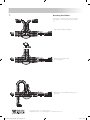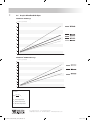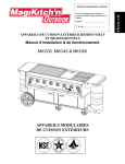
1
Flexibility, all the way.
Technical
Manual
Edition 2015
Flexibility is in our nature
mic_xxxxxx_technisch-handb_150223_ENG.indd 1
23/02/15 16:07
mic_xxxxxx_technisch-handb_150223_ENG.indd 2
23/02/15 16:07
THE FLEXIBLE
PRE-INSULATED
PIPING SYSTEM
• System Description
• Product Range
• Points of Attention for Assembly
• Operating Instructions
• Appendix
Microflex’s quality management systems are certified in accordance with NBN EN ISO-9001: 2008.
mic_xxxxxx_technisch-handb_150223_ENG.indd 3
23/02/15 16:07
4
Contents
Page
1. System Description
1.1 Description ......................................................................................................................... 5
1.2 Fields of Application ..................................................................................................... 5
1.3 Properties ............................................................................................................................ 5
1.4 Structure of the Microflex System ........................................................................ 6
1.5 PE-Xa Carrier Pipe ........................................................................................................... 7
1.6 Insulating Material ......................................................................................................... 9
1.7 Corrugated PE-HD Double-Walled Casing ..................................................... 9
1.8 Dimensions of Coils .................................................................................................... 10
2. Product Range
2.1 Pre-Insulated Pipes ...................................................................................................... 11
2.2 PE-X Couplings ............................................................................................................... 13
2.3 Accessories ....................................................................................................................... 19
3. Points of Attention for Assembly
3.1 Transport and Storage ............................................................................................... 25
3.2 Pipe Cutting ..................................................................................................................... 25
3.3 Instructions for Laying Microflex Pipes in Soil ............................................ 25
3.4 Mounting onto Walls or Ceilings.......................................................................... 27
3.5 Guidelines for Pipe Laying on the Ground Surface ................................. 27
3.6 MICRO SEAL Wall Feedthrough (Subterranean Use) .............................. 28
3.7 MMDV Wall Feedthrough (Surface/Above Ground Use) ...................... 28
3.8 Securing the Pipe ......................................................................................................... 29
3.9 Shrink Caps Type MK .................................................................................................. 29
3.10 EPDM Rubber End-Caps ........................................................................................... 29
3.11 Couplings .......................................................................................................................... 30
3.12 Self-Regulating Heating Cable ............................................................................. 30
3.13 Insulation Kits .................................................................................................................. 31
3.14 Inspection Chamber ................................................................................................... 32
3.15 Pressure Test ..................................................................................................................... 33
3.16 Backfilling Guidelines ................................................................................................. 34
3.17 Before Usage ................................................................................................................... 34
4. Operating Instructions
4.1 MICRO SEAL Wall Feedthrough (Subterranean Use) .............................. 35
4.2 MMDV Wall Feedthrough (Surface/Above Ground Use) ..................... 36
4.3 Shrink Caps Type MK .................................................................................................. 38
4.4 EPDM Rubber End-Caps ................................................................................................. 39
4.5 Microflex PE-X Couplings ........................................................................................ 40
4.6 Self-Regulating Heating Cable .............................................................................. 41
4.7 Insulation Kits ................................................................................................................... 45
4.8 Insulated Straight Coupling Kit Type MM75 – MM200 ......................... 48
4.9 Inspection Chamber .................................................................................................... 49
4.10 MHK 150 Cold-Applied Wrapping Tape ........................................................... 53
4.11 MHB 200 Heat-Shrinkable Wrapping Tape..................................................... 54
4.12 MHM Shrink Sleeve ..................................................................................................... 55
5. Appendix
5.1 Equivalent Pipe Length for a Bending Angle of 45° and 90° ............. 56
5.2 Pipe Capacity ................................................................................................................... 57
5.3 Determine the Necessary Power of the Heat Source ............................ 57
5.4 Graphs – Microflex UNO Pipes ............................................................................. 58
5.5 Tables – UNO Pipes....................................................................................................... 59
5.6 Graphs – Microflex DUO Pipes .............................................................................. 60
5.7 Tables – DUO Pipes....................................................................................................... 61
5.8 Pressure Loss Tables ..................................................................................................... 62
5.9 Chemical Resistance: PE-Xa Carrier Pipe ........................................................ 64
5.10 Heat Loss Table for Heated Cool Pipes ............................................................ 65
5.11 Self-Regulating Heating Cables: Structure and Operation ................. 66
5.12 Conversion Tables ........................................................................................................ 67
Tel. + 32 (0)16 44 21 31 • Fax + 32 (0)16 44 03 68
[email protected] • www.microflex.be • www.wattsinsulation.com
A Company of Watts Water Technologies EMEA B.V.
mic_xxxxxx_technisch-handb_150223_ENG.indd 4
23/02/15 16:07
1.
5
System Description
1.1 Description
Essential for energy saving is a well performing piping system. Microflex’s preinsulated piping system, composed of a thermal insulation around a carrier
pipe and covered by a “closed chamber “ protective casing, is therefore your
best choice.
Microflex piping is suitable for use in heating, cooling and sanitary applications and provides significant advantages such as, low-weight, hyper flexibility, robustness, and easy and rapid laying even over obstacles and around
corners. System accessories can be mounted without any special tools.
Our PE-Xa Central Heating carrier pipe (made from cross-linked polyethylene)
is oxygen diffusion proof in accordance with DIN 4726. It can transport a large
number of different liquids and is fully corrosion free.
Microflex® is made available as a single, twin or quadruple piping system. It is
manufactured free of CFCs.
1.2 Fields of Application
• Heating
• Hot Water Distribution
• Supply to Individual Buildings
• Distribution Inside Buildings
• Local or Remote Heating Networks
• Sanitary Water
• Distribution of Potable and Non-Potable Water
• Renewable Energy
•
•
•
•
•
Heat Pumps
Biogas and Biomass Installations
Combined Heat and Power (CHP)
Pellet Fuels
Geothermal Applications
• Special Applications
•
•
•
•
Transport of Chemicals
Food Industry
Cooling Systems
Swimming Pools, Leisure Centres
1.3 Properties
•
•
•
•
•
•
•
•
Versatility
Oxygen Diffusion Barrier to DIN 4726
Low Weight
Completely Corrosion Resistant
Environmentally Friendly Manufacture
Maintenance Free
Long Life Expectancy
Superior Quality
Tel. + 32 (0)16 44 21 31 • Fax + 32 (0)16 44 03 68
[email protected] • www.microflex.be • www.wattsinsulation.com
A Company of Watts Water Technologies EMEA B.V.
mic_xxxxxx_technisch-handb_150223_ENG.indd 5
23/02/15 16:07
6
1.4 Structure of the Microflex System
The Microflex piping system consists of three integrated components and
is manufactured according to the EN 15632: 1-3 norm
• Piping system with one pipe: UNO
Corrugated twin wall
outer casing (PE-HD)
Microflex UNO
PN 6 - PN 10 - PN 16
Carrier Pipe (cross-linked
PE-Xa or PE-100)
Insulation
(cross-linked PE foam)
Piping system with two pipes: DUO
Microflex DUO
PN 6 - PN 10 - PN 16
• Piping system with four pipes: QUADRO
Microflex QUADRO
2 x PN 6 - 2 x PN 10
The Hyper Flexibility of the Microflex® Piping System
0,6
m
- Placement of the pipe over obstacles and around corners is possible.
- The inside bending radii of the different pipes are specified in the Product
Range Tables (see section 2.1). Measurements are taken from the inside of
the pipe. A reserve factor is taken into account.
- For example: two PE-Xa pipes of Ø 40 mm can form a curve with an inside
radius of 0.6m (see picture).
Tel. + 32 (0)16 44 21 31 • Fax + 32 (0)16 44 03 68
[email protected] • www.microflex.be • www.wattsinsulation.com
A Company of Watts Water Technologies EMEA B.V.
mic_xxxxxx_technisch-handb_150223_ENG.indd 6
23/02/15 16:07
7
1.5 PE-Xa Carrier Pipe
The carrier or media transport pipe, as it is often called, used by Microflex is
a PE-Xa pipe, which is manufactured according to DIN 16892/16893 and ISO
15875 standards. PE-Xa stands for cross-linked PE, whereby cross-connections
between the PE molecules are formed. The resulting molecule is more resistant to extremes of temperatures/pressures and chemical attack.
Thermal Properties
The life expectancy of the pipe is highly dependent on a combination of pressures and temperatures. The carrier pipe has a life expectancy of 50 years, as
detailed in the enclosed table, when the pressure and temperature are kept
constant and thus meets the ISO 15875 norm.
Life expectancy PE-Xa pipes at constant
pressure and temperature
(safety factor C=1,25)
Temperature
Life
expectancy
This table serves as a general guideline. In practice, it’s necessary to take into
account widely varying pressures and temperatures.
SDR
11
7.4
operating pressure
bar
The pipes are, in normal operation, able to withstand operating temperatures
and pressures of 85°C / 6 bar for heating and 85°C / 10 bar for sanitary installations.
For a short time, the material is also resistant to temperatures of 95°C.
°C
years
10
50
17.1
27.1
20
50
15.1
24.0
30
50
13.4
21.3
40
50
11.9
18.9
50
50
10.6
16.8
60
50
9.5
15.0
70
50
8.5
13.4
80
50
7.5
12.0
Most chemicals have no influence on the pipe, even at elevated temperatures. Typically, plastics that are exposed to chemical substances are prone
to physical changes in their properties, such as, swelling or dissolution of the
polymers. Due to the chemical bonding of the polymer chains, PE-Xa pipes
(cross-linked PE) are more resilient in that respect than pipes of non-crosslinked PE. In order to assess the resistance to different materials changes in
the tensile and elongation characteristics were monitored. In a pressurised
piping system the resistance to unknown chemicals cannot generally be extrapolated from experience of known chemicals. For this, durability tests with
the unknown chemicals in test piping are required. For the list of Chemical
Resistance, see Appendix, section 5.9.
90
50
6.8
10.9
High Abrasion Resistance
Chemical Resistance
PE-Xa pipes provide an enhanced abrasion resistance and durability. Pipes
conveying aggressive sludge at fairly high velocities do not suffer internal erosion.
Pipe Roughness
The smooth bore offers less resistance to flow than conventional pipes resulting in excellent flow characteristics with minimal flow loss without formation
of any sedimentary deposits.
Environmentally Friendly
PE-Xa pipes are certified to comply with international potable water quality
requirements such as DVGW, WRAS and ACS (copies of the certificates are
available on request). The pipe imparts neither taste nor odour and is non-toxic.
Consequently it is ideally suited for different branches of the food industry.
Tel. + 32 (0)16 44 21 31 • Fax + 32 (0)16 44 03 68
[email protected] • www.microflex.be • www.wattsinsulation.com
A Company of Watts Water Technologies EMEA B.V.
mic_xxxxxx_technisch-handb_150223_ENG.indd 7
23/02/15 16:07
8
Oxygen Diffusion Barrier
The PE-Xa carrier pipe for central heating applications also features an oxygen
diffusion barrier (EVOH) that prevents oxygen permeating into the piping system (according DIN 4726). Such an oxygen barrier layer enhances the life of
any ferrous components of the system (pumps, valves, etc.)
Material Properties PE-Xa Pipes
Mechanical Properties
Temp
Standard
Value
Unit
Density
938
kg/m3
Cross Linking Degree
80
%
Elasticity Modulus
@ 20 °C
DIN 53457
600 - 900
N/mm2
Tensile Strength
@ 20 °C
DIN 53455
19
N/mm2
Elongation at Break
@ 20 °C
DIN 53455
> 400
%
Moisture Absorption
@ 20 °C
< 0.01
mg/4day
Oxygen Permeability
@ 80 °C
0.02
mg/lday
0.007
mm
Value
Unit
-80+110
°C
DIN 4726
Roughness Factor
Thermal Properties
Temp
Operating Temperature
Coefficient of Linear
Expansion
@ 20 °C
@ 100 °C
Standard
1.4 X 10⁻⁴
2.0 X 10⁻⁴
Softening Temperature
Coefficient of Thermal
Conductivity
@ 20 °C
1/K
1/K
133
°C
0.35
W/mK
Tel. + 32 (0)16 44 21 31 • Fax + 32 (0)16 44 03 68
[email protected] • www.microflex.be • www.wattsinsulation.com
A Company of Watts Water Technologies EMEA B.V.
mic_xxxxxx_technisch-handb_150223_ENG.indd 8
23/02/15 16:07
9
1.6 Insulating Material
CFC
CFK
The insulating material used consists of microcellular, cross-linked polyethy–
lene foam. In addition to the excellent insulating properties, the closed-cell
structure of the material ensures that there is only minimal water absorption.
The material is CFC free.
Durability
The closed cell structure ensures optimal quality preservation with constant
insulation performance throughout its long service life.
C fre
The shape memory of the cross-linked polyethylene foam makes it permanently elastic and ensures the continuance of the initial insulation performance, even after repeated rolling, unrolling and bending of the system. The
durable insulation performance makes the Microflex pipe therefore extremely
resistant to aging.
e
CF
free
Insulation Material Properties
Temp
Density
Standard
Value
Unit
ISO 845
28.0
kg/m3
Tensile Strength Longitudinally at Fracture
@ 23 °C
ISO 1926
299.0
kPa
Longitudinal Elongation at Fracture
@ 23 °C
ISO 1926
122.0
%
100
°C
ISO 2896
<1
%
ISO 8301
0.040
W/mK
Thermal Stability: Max Temperature
Water Absorption
Thermal Conductivity
@ 40 °C
1.7 Corrugated PE-HD Double-Walled Casing
The outer cover made from PE-HD following the “closed chamber” principle,
protects the inner pipe as well as the insulating material from external impacts. The ribs of the corrugated outer cover are completely closed; water
ingress due to superficial damage to the outer cover is therefore impossible.
Due to the corrugated structure, the piping has longitudinal flexibility and
resistance to impacts.
Microflex piping is very robust and resistant to aggressive substances.
Tel. + 32 (0)16 44 21 31 • Fax + 32 (0)16 44 03 68
[email protected] • www.microflex.be • www.wattsinsulation.com
A Company of Watts Water Technologies EMEA B.V.
mic_xxxxxx_technisch-handb_150223_ENG.indd 9
23/02/15 16:07
10
1.8 Dimensions of Coils
The standard length of a coil is 100m. Tailored lengths can be cut. The coils are
designed to fit standard HGV trailers and containers. For transport and storage
specifications see section 3.1.
Casing Ø
Coil Inner Ø
Coil Outer Ø
Coil Width
mm
mm
mm
mm
LM
Microflex UNO
75
1200
1900
300
0.3
90
1200
1850
500
0.45
125
1200
2100
700
0.7
160
1200
2350
850
0.8
200
1200
2300
1400
1.4
Microflex DUO for Central Heating – Cooling Systems
125
1200
2100
700
0.7
160
1200
2350
850
0.8
200
1200
2300
1400
1.4
1200
2350
850
0.8
Microflex QUADRO
160
Tel. + 32 (0)16 44 21 31 • Fax + 32 (0)16 44 03 68
[email protected] • www.microflex.be • www.wattsinsulation.com
A Company of Watts Water Technologies EMEA B.V.
mic_xxxxxx_technisch-handb_150223_ENG.indd 10
23/02/15 16:07
11
2. Product Range
<
s
2.1 Pre-Insulated Pipes
Outer Casing dout
a.
Central Heating
Standard Range
Pipe
PE-Xa
dout x s
PE-Xa
din
Outer Casing
dout
Weight
Inner
Bending
Radius
Average
Thickness of
Insulation
Art. No.
mm
DN
mm
kg/m
m
mm
Microflex UNO PN 6 / 95°C
SDR 11
M7525 C
25 x 2.3
20
75
0.65
0.20
19.0
M9032 C
32 x 2.9
25
90
1.00
0.25
21.5
M16040 C
40 x 3.7
32
160
2.19
0.35
49.0
M16050 C
50 x 4.6
40
160
2.43
0.45
44.0
M16063 C
63 x 5.8
50
160
2.72
0.55
37.5
M20075 C
75 x 6.8
65
200
3.99
0.80
48.5
M20090 C
90 x 8.2
75
200
4.58
1.10
41.0
M200110 C
110 x 10.0
90
200
5.53
1.20
31.0
M200125 C
125 x 11.4
100
200
6.48
1.40
23.5
Microflex DUO PN 6 / 95°C
Economy Range
SDR 11
MD16025 C
2 x 25/2.3
20
160
2.07
0.50
MD16032 C
2 x 32/2.9
25
160
2.31
0.50
MD16040 C
2 x 40/3.7
32
160
2.57
0.60
MD20050 C
2 x 50/4.6
40
200
3.93
0.80
MD20063 C
2 x 63/5.8
50
200
4.70
1.20
Microflex Primo UNO PN 6 / 95°C
SDR 11
M9040 C
40 x 3.7
32
90
1.16
0.30
17.5
M12540 C
40 x 3.7
32
125
1.68
0.30
33.0
M12550 C
50 x 4.6
40
125
1.92
0.40
28.0
M12563 C
63 x 5.8
50
125
2.19
0.50
21.5
M16075 C
75 x 6.8
65
160
3.10
0.75
31.5
M16090 C
90 x 8.2
75
160
3.69
1.00
24.0
Microflex Primo DUO PN 6 / 95°C
b.
Quadro
SDR 11
MD12525 C
2 x 25/2.3
20
125
1.60
0.40
MD12532 C
2 x 32/2.9
25
125
1.78
0.40
MD16050 C
2 x 50/4.6
40
160
3.02
0.70
Microflex QUADRO PN 6 Central Heating / PN 10 Sanitary
SDR 11 / SDR 7.4
MQ16025C2520S
25 x 2.3 C (2 x)
25 x 3.5 S (1 x)
20 x 2.8 S (1 x)
20
20
15
160
2.49
0.60
MQ16032C2520S
32 x 2.9 C (2 x)
25 x 3.5 S (1 x)
20 x 2.8 S (1 x)
25
20
15
160
2.65
0.60
MQ16032C3225S
32 x 2.9 C (2 x)
32 x 4.4 S (1 x)
25 x 3.5 S (1 x)
25
25
20
160
2.88
0.60
Tel. + 32 (0)16 44 21 31 • Fax + 32 (0)16 44 03 68
[email protected] • www.microflex.be • www.wattsinsulation.com
A Company of Watts Water Technologies EMEA B.V.
mic_xxxxxx_technisch-handb_150223_ENG.indd 11
23/02/15 16:08
12
c.
Sanitary Applications
Standard Range
Pipe
PE-Xa
dout x s
Art. No.
mm
PE-Xa Outer Casing
din
dout
DN
mm
Weight
Inner
Bending
Radius
Average
Thickness of
Insulation
kg/m
m
mm
Microflex UNO PN 10 / 95°C
SDR 7.4
M7525 S
25 x 3.5
20
M9032 S
32 x 4.4
M12540 S
40 x 5.5
M12550 S
M12563 S
75
0.73
0.20
19.0
25
90
1.13
0.25
21.5
32
125
1.82
0.40
33.0
50 x 6.9
40
125
2.09
0.50
28.0
63 x 8.7
50
125
2.70
0.60
21.5
Microflex DUO PN 10 / 95°C
MD16025 S
Economy Range
d.
Cool without Self-Regulating
Heating Cable
2 x 25/3.5
MD1603225 S
1 x 32/1 x 25
MD1604025 S
1 x 40/1 x 25
MD1605025 S
1 x 50/1 x 25
MD1605032 S
1 x 50/1 x 32
SDR 7.4
20
25
20
32
20
40
20
40
25
160
2.23
0.50
160
2.37
0.50
160
2.57
0.60
160
2.90
0.60
160
3.02
0.60
Microflex Primo DUO PN 10 / 95°C
MD1252520 S
1 x 25/1 x 20
MD1253225 S
1 x 32/1 x 25
Pipe
PE-Xa
dout x s
Art. No.
mm
SDR 7.4
20
15
25
20
125
1.64
0.40
125
1.86
0.40
Weight
Inner
Bending
Radius
Average
Thickness of
Insulation
kg/m
m
mm
PE-Xa Outer Casing
din
dout
DN
mm
Microflex Cool UNO without Self-Regulating Heating Cable PN 16 / 25°C
SDR 11
M9032 PE
32 x 2.9
25
90
1.03
0.25
21.5
M9040 PE
40 x 3.7
32
90
1.16
0.30
17.5
M12550 PE
50 x 4.6
40
125
1.90
0.40
28.0
M12563 PE
63 x 5.8
50
125
2.21
0.50
21.5
M16075 PE
75 x 6.8
65
160
3.14
0.75
31.5
M16090 PE
90 x 8.2
75
160
3.73
1.00
24.0
M200110 PE
110 x 10.0
90
200
5.57
1.20
31.0
M200125 PE
125 x 11.4
100
200
6.44
1.40
Microflex Cool DUO PN 16 / 25°C
e.
Cool with Self-Regulating
Heating Cable
23.5
SDR 11
MD12532 PE
2 x 32/2.9
25
125
1.82
0.40
MD16040 PE
2 x 40/3.7
32
160
2.63
0.60
MD16050 PE
2 x 50/4.6
40
160
3.10
0.60
MD20063 PE
2 x 63/5.8
50
200
4.64
1.20
Microflex Cool UNO with Self-Regulating Heating Cable PN 16 / 25°C
SDR 11
MV7532 PE
32 x 2.9
25
75
0.81
0.25
15.5
MV9040 PE
40 x 3.7
32
90
1.26
0.30
17.5
MV12550 PE
50 x 4.6
40
125
1.95
0.50
28.0
MV12563 PE
63 x 5.8
50
125
2.31
0.60
21.5
MV16075 PE
75 x 6.8
65
160
3.20
0.75
31.5
MV16090 PE
90 x 8.2
75
160
3.77
1.00
24.0
MV200110 PE
110 x 10.0
90
200
5.65
1.20
31.0
MV200125 PE
125 x 11.4
100
200
6.46
1.40
23.5
Tel. + 32 (0)16 44 21 31 • Fax + 32 (0)16 44 03 68
[email protected] • www.microflex.be • www.wattsinsulation.com
A Company of Watts Water Technologies EMEA B.V.
mic_xxxxxx_technisch-handb_150223_ENG.indd 12
23/02/15 16:08
13
2.2 PE-X Couplings
All PE-X couplings are made of brass (EN 12165). All clamping rings are made of brass that is resistant to
dezincification (DZR – ISO 6509). The material of the pipe sections meets the latest potable water directives.
2.2.1.
Microflex PE-X Terminal Connections for Central Heating and Cooling
Applications PN 6 (PN 16) – SDR 11
ø Pipe / Wall Thickness
Ø External Thread
Ø Outer Diameter of Pipe
mm
inch
mm
MJ3413425/23
25 / 2.3
3/4”
25
MJ3414432/29
32 / 2.9
1”
32
MJ3415440/37
40 / 3.7
1 1/4”
40
MJ3416450/46
50 / 4.6
1 1/2”
50
MJ341263/58
63 / 5.8
2”
63
MJ34121275/68
75 / 6.8
2 1/2”
75
MJ341390/82
90 / 8.2
3”
90
MJ3414110/100
110 / 10.0
4”
110
MJ3414125/114
125 / 11.4
4”
125
MJ27025/23
25 / 2.3
2 x 3/4”
25 x 25
MJ27032/29
32 / 2.9
2 x 1”
32 x 32
MJ27040/37
40 / 3.7
2 x 1 1/4”
40 x 40
MJ27050/46
50 / 4.6
2 x 1 1/2”
50 x 50
MJ27063/58
63 / 5.8
2 x 2”
63 x 63
MJ27075/68
75 / 6.8
2 x 2 1/2”
75 x 75
Art. No.
Straight Coupling, Male
PE-X x PE-X Straight Coupling
MJ27090/82
90 / 8.2
2 x 3”
90 x 90
MJ270110/100
110 / 10.0
2 x 4”
110 x 110
MJ270125/114
125 / 11.4
2 x 4”
125 x 125
MJ9025/23
25 / 2.3
2 x 3/4”
25 x 25
MJ9032/29
32 / 2.9
2 x 1”
32 x 32
MJ9040/37
40 / 3.7
2 x 1 1/4”
40 x 40
MJ9050/46
50 / 4.6
2 x 1 1/2”
50 x 50
MJ9063/58
63 / 5.8
2 x 2”
63 x 63
MJ9075/68
75 / 6.8
2 x 2 1/2”
75 x 75
PE-X x PE-X Elbow Coupling
MJ9090/82
90 / 8.2
2 x 3”
90 x 90
MJ90110/100
110 / 10.0
2 x 4”
110 x 110
MJ90125/114
125 / 11.4
2 x 4”
125 x 125
Tel. + 32 (0)16 44 21 31 • Fax + 32 (0)16 44 03 68
[email protected] • www.microflex.be • www.wattsinsulation.com
A Company of Watts Water Technologies EMEA B.V.
mic_xxxxxx_technisch-handb_150223_ENG.indd 13
23/02/15 16:08
14
Tee-Coupling 3 x PE-X
MJ13025/23
25 / 2.3
3 x 3/4”
25 x 25 x 25
MJ13032/29
32 / 2.9
3 x 1”
32 x 32 x 32
40 / 3.7 + 32 / 2.9
2 x 1 1/4”+ 1 x 1”
40 x 32 x 40
40 / 3.7
3 x 1 1/4”
40 x 40 x 40
50 / 4.6 + 40 / 3.7
2 x 1 1/2”+ 1 x 1 1/4”
50 x 40 x 50
50 / 4.6
3 x 1 1/2”
50 x 50 x 50
63 / 5.8 + 50 / 4.6
2 x 2” + 1 x 1 1/2”
63 x 50 x 63
MJ1304032/37
MJ13040/37
MJ1305040/46
MJ13050/46
MJ1306350/58
MJ13063/58
63 / 5.8
3 x 2”
63 x 63 x 63
MJ13075/68
75 / 6.8
3 x 2 1/2”
75 x 75 x 75
MJ13090/82
90 / 8.2
3 x 3”
90 x 90 x 90
MJ130110/100
110 / 10.0
3 x 4”
110 x 110 x 110
MJ130125/114
125 / 11.4
3 x 4”
125 x 125 x 125
Ø Pipe / Wall Thickness
Ø dext
Ø dint
mm
mm
mm
MJ3412725/23L
25 / 2.3
26.90
21.50
MJ3413332/29L
32 / 2.9
33.70
27.00
MJ3414240/37L
40 / 3.7
42.40
36.00
MJ3414550/46L
50 / 4.6
48.30
42.00
MJ3415763/58L
63 / 5.8
60.30
53.00
MJ3417675/68L
75 / 6.8
76.10
68.00
MJ3418990/82L
90 / 8.2
88.90
80.00
MJ341110110/10L
110 / 10.0
114.30
105.00
MJ341114125/114L
125 / 11.4
114.30
105.00
Art. No.
Weld-End Coupling
dint
dext
Tel. + 32 (0)16 44 21 31 • Fax + 32 (0)16 44 03 68
[email protected] • www.microflex.be • www.wattsinsulation.com
A Company of Watts Water Technologies EMEA B.V.
mic_xxxxxx_technisch-handb_150223_ENG.indd 14
23/02/15 16:08
2.2.2.
Microflex PE-X Couplings for Sanitary Applications PN 10 – SDR 7.4
Ø Pipe / Wall Thickness
Ø External Thread
Ø Outer Diameter of Pipe
mm
inch
mm
MJ3413420/28
20 / 2.8
3/4”
20
MJ3413425/35
25 / 3.5
3/4”
25
MJ3414432/44
32 / 4.4
1”
32
MJ3415440/55
40 / 5.5
1 1/4”
40
MJ3416450/69
50 / 6.9
1 1/2”
50
MJ341263/87
63 / 8.7
2”
63
Art. No.
15
Straight Coupling, Male
PE-X x PE-X Coupling
MJ27025/35
25 / 3.5
2 x 3/4”
25 x 25
MJ27032/44
32 / 4.4
2 x 1”
32 x 32
MJ27040/55
40 / 5.5
2 x 1 1/4”
40 x 40
MJ27050/69
50 / 6.9
2 x 1 1/2”
50 x 50
MJ27063/87
63 / 8.7
2 x 2”
63 x 63
MJ9025/35
25 / 3.5
2 x 3/4”
25 x 25
MJ9032/44
32 / 4.4
2 x 1”
32 x 32
MJ9040/55
40 / 5.5
2 x 1 1/4”
40 x 40
MJ9050/69
50 / 6.9
2 x 1 1/2”
50 x 50
MJ9063/87
63 / 8.7
2 x 2”
63 x 63
25 / 3.5
3 x 3/4”
25 x 25 x 25
32 / 4.4
3 x 1”
32 x 32 x 32
40 / 5.5 + 32 / 4.4
2 x 1 1/4” + 1 x 1”
40 x 32 x 40
PE-X x PE-X Elbow Coupling
Tee-Coupling 3 x PE-X
MJ13025/35
MJ13032/44
MJ1304032/55
MJ13040/55
MJ1305040/69
MJ13050/69
MJ1306350/87
MJ13063/87
40 / 5.5
3 x 1 1/4”
40 x 40 x 40
50 / 6.9 + 40 / 5.5
2 x 1 1/2” + 1 x 1 1/4”
50 x 40 x 50
50 / 6.9
3 x 1 1/2”
50 x 50 x 50
63 / 8.7 + 50 / 6.9
2 x 2” + 1 x 1 1/2”
63 x 50 x 63
63 / 8.7
3 x 2”
63 x 63 x 63
Tel. + 32 (0)16 44 21 31 • Fax + 32 (0)16 44 03 68
[email protected] • www.microflex.be • www.wattsinsulation.com
A Company of Watts Water Technologies EMEA B.V.
mic_xxxxxx_technisch-handb_150223_ENG.indd 15
23/02/15 16:08
16
2.2.3.
Accessories for PE-X Couplings
Art. No.
Ø inch
Fix Point
Bronze – Conical Male
Thread (ISO 7)
- Parallel Female
Thread (ISO 228)
MFP34
MFP44
MFP54
MFP64
MFP2
MFP212
MFP3
MFP4
3/4”
1”
1 1/4”
1 1/2”
2”
2 1/2”
3”
4”
Sleeve F x F
Bronze – Parallel Thread
(ISO 228)
VW27034
VW27044
VW27054
VW27064
VW2702
VW270212
VW2703
VW2704
3/4”
1”
1 1/4”
1 1/2”
2”
2 1/2”
3”
4”
Elbow 90° F x F
Bronze – Parallel Thread
(ISO 228)
VW9034
VW9044
VW9054
VW9064
VW902
VW90212
VW903
VW904
3/4”
1”
1 1/4”
1 1/2”
2”
2 1/2”
3”
4”
Tee F x F x F
Bronze – Parallel Thread
(ISO 228)
VW13034
VW13044
VW13054
VW13064
VW1302
VW130212
VW1303
VW1304
3/4”
1”
1 1/4”
1 1/2”
2”
2 1/2”
3”
4”
Reducing Bush M x F
Brass – Parallel Thread
(ISO 228)
VW2414434
VW2415434
VW2415444
VW2416434
VW2416444
VW2416454
VW241234
VW241244
VW241254
VW241264
VW24121254
VW24121264
VW2412122
1” x 3/4”
1 1/4” x 3/4”
1 1/4” x 1”
1 1/2” x 3/4”
1 1/2” x 1”
1 1/2” x 1 1/4”
2” x 3/4”
2” x 1”
2” x 1 1/4”
2” x 1 1/2”
2 1/2” x 1 1/4”
2 1/2” x 1 1/2”
2 1/2” x 2”
Tel. + 32 (0)16 44 21 31 • Fax + 32 (0)16 44 03 68
[email protected] • www.microflex.be • www.wattsinsulation.com
A Company of Watts Water Technologies EMEA B.V.
mic_xxxxxx_technisch-handb_150223_ENG.indd 16
23/02/15 16:08
17
Art. No.
Ø inch
Reducing Bush M x F
VW241344
VW241354
VW241364
VW24132
VW2413212
VW24142
VW2414212
VW24143
3” x 1”
3” x 1 1/4”
3” x 1 1/2”
3” x 2”
3” x 2 1/2”
4” x 2”
4” x 2 1/2”
4” x 3”
Screwed Flange
Galvanised Steel
MDF34
MDF44
MDF54
MDF64
MDF2
MDF212
MDF3
MDF4
3/4”
1”
1 1/4”
1 1/2”
2”
2 1/2”
3”
4”
Nipples
Nickel Plated Brass –
Conical Thread (ISO 7)
VW28034
VW28044
VW28054
VW28064
VW2802
VW280212
VW2803
VW2804
3/4”
1”
1 1/4”
1 1/2”
2”
2 1/2”
3”
4”
Stop
Nickel Plated Brass –
Parallel Thread (ISO 228)
VW29034
VW29044
VW29054
VW29064
VW2902
VW290212
VW2903
VW2904
3/4”
1”
1 1/4”
1 1/2”
2”
2 1/2”
3”
4”
Ball Valve
Nickel Plated Brass
VW35034
VW35044
VW35054
VW35064
VW3502
VW350212
VW3503
VW3504
3/4”
1”
1 1/4”
1 1/2”
2”
2 1/2”
3”
4”
Tel. + 32 (0)16 44 21 31 • Fax + 32 (0)16 44 03 68
[email protected] • www.microflex.be • www.wattsinsulation.com
A Company of Watts Water Technologies EMEA B.V.
mic_xxxxxx_technisch-handb_150223_ENG.indd 17
23/02/15 16:08
18
2.2.4. PE Couplings
Maximum working pressure at 20 °C: 16 bar for 32 - 63mm
Maximum working pressure at 20 °C: 10 bar for 75 – 110mm
The PE couplings are made from Polypropylene and are for use in cold and
cooling water systems. These are ideal for use in chlorine environments, e.g.
swimming pool. Suitable for connecting PE carrier transport pipes.
Male-threaded coupling
PE x PE Pipe Coupling
PE x PE Elbow Piece
Art. No.
MPP3414432/29
MPP3415440/37
MPP3416450/46
MPP341263/58
MPP34121275/68
MPP341390/82
MPP3414110/100
Art. No.
MPP27032/29
MPP27040/37
MPP27050/46
MPP27063/58
MPP27075/68
MPP27090/82
MPP270110/100
Art. No.
MPP9032/29
MPP9040/37
MPP9050/46
MPP9063/58
MPP9075/68
MPP9090/82
MPP90110/100
3 x PE T-Piece
Art. No.
MPP13032/29
MPP13040/37
MPP13050/46
MPP13063/58
MPP13075/68
MPP13090/82
MPP130110/100
PE dout/S
Thread
mm
inch
32 / 2.9
40 / 3.7
50 / 4.6
63 / 5.8
75 / 6.8
90 / 8.2
110 / 10.0
1” M
1 1/4” M
1 1/2” M
2” M
2 1/2” M
3” M
4” M
PE dout/S
PE dout x dout
mm
mm
32 / 2.9
40 / 3.7
50 / 4.6
63 / 5.8
75 / 6.8
90 / 8.2
110 / 10.0
32 x 32
40 x 40
50 x 50
63 x 63
75 x 75
90 x 90
110 x 110
PE dout/S
PE dout x dout
mm
mm
32 / 2.9
40 / 3.7
50 / 4.6
63 / 5.8
75 / 6.8
90 / 8.2
110 / 10.0
32 x 32
40 x 40
50 x 50
63 x 63
75 x 75
90 x 90
110 x 110
PE dout/S
PE dout x dout x dout
mm
mm
32 / 2.9
40 / 3.7
50 / 4.6
63 / 5.8
75 / 6.8
90 / 8.2
110 / 10.0
32 x 32 x 32
40 x 40 x 40
50 x 50 x 50
63 x 63 x 63
75 x 75 x 75
90 x 90 x 90
110 x 110 x 110
Tel. + 32 (0)16 44 21 31 • Fax + 32 (0)16 44 03 68
[email protected] • www.microflex.be • www.wattsinsulation.com
A Company of Watts Water Technologies EMEA B.V.
mic_xxxxxx_technisch-handb_150223_ENG.indd 18
23/02/15 16:08
19
2.3 Accessories
2.3.1. Microflex Dust Caps prevent the ingress of dust.
Dimensions in mm
Art. No.
Dust caps for Microflex UNO
MS7525
MS7532
MS9032
MS9040
MS12540
MS12550
MS12563
MS16040
MS16050
MS16063
MS16075
MS16090
MS20075
MS20090
MS200110
MS200125
MSD12525
MSD12532
MSD16025
MSD16032
MSD16040
MSD16050
MSD20050
MSD20063
MSD1252520
MSD1253225
MSD1603225
MSD1604025
MSD1605025
MSD1605032
MSQ160252520
MSQ160322520
MSQ160323225
Dust caps for Microflex DUO
Dust caps for Microflex QUADRO
Ø Outer Casing
75
75
90
90
125
125
125
160
160
160
160
160
200
200
200
200
125
125
160
160
160
160
200
200
125
125
160
160
160
160
160
160
160
Ø Pipe
25
32
32
40
40
50
63
40
50
63
75
90
75
90
110
125
2 x 25
2 x 32
2 x 25
2 x 32
2 x 40
2 x 50
2 x 50
2 x 63
1x25/1x20
1x32/1x25
1x32/1x25
1x40/1x25
1x50/1x25
1x50/1x32
2x25/1x25/1x20
2x32/1x25/1x20
2x32/1x32/1x25
2.3.2. Microflex Heat Shrinkable Caps are used for preventing the ingress of water between the
outer casing and insulated carrier pipe. Pressure resistant up to 0.3 bar.
Dimensions in mm
Art. No.
Heat shrink caps for UNO
MK2000
MK2100
MK2200
MK2400
MK2340
MK2500
MK2600
MK3250-P604
MK3250-P604
MK3250-P604
MK3280
MK3350-01
MK3350-02
MK3350-01
MK3350-02
MK3360-01
MK3350-03
MK3350-03
MK3350-03
MK3350-05
Heat shrink caps for DUO
Ø Outer Casing
Ø Pipe
75
75/90
125
125
160
160
200
125
125
125
125
160
160
160
160
160
160
160
200
200
25
32 of 40
40 of 50
63
40 of 50
63 tot 90
75 tot 125
1x25/1x20
2x25
1x32/1x25
2 x 32
2x25 of 2 x 32
2 x 40
1x32/1x25
1x40/1x25
1x50/1x25
1x50/1x32
2 x 50
2 x 50
2x63
Tel. + 32 (0)16 44 21 31 • Fax + 32 (0)16 44 03 68
[email protected] • www.microflex.be • www.wattsinsulation.com
A Company of Watts Water Technologies EMEA B.V.
mic_xxxxxx_technisch-handb_150223_ENG.indd 19
23/02/15 16:08
20
2.3.3. Microflex EPDM Rubber End-Caps are used for preventing the ingress of water
between the outer casing and insulated carrier pipe. Pressure resistant up to 0.3 bar.
Dimensions in mm
Art. No.
EPDM Rubber end-cap for UNO
MG751832
MG901840
MG1252532
MG1254063
MG1603250
MG1606390
MG20075125
MGD1251832
MGD1601840
MGD1602550
MGD2004063
EPDM Rubber end-cap for DUO
Ø Outer Casing
75
90
125
125
160
160
200
125
160
160
200
Ø Pipe
1 x 18, 25, 28 of 32
1 x 18, 25, 32 of 40
1 x 25, 28 of 32
1 x 40, 50 of 63
1 x 32, 40 of 50
1 x 63, 75 of 90
1 x 75, 90, 110 of 125
2 x 18, 20, 25, 28 of 32
2 x 18, 28, 32 of 40
2 x 25, 32, 40 of 50
2 x 40, 50 of 63
2.3.4. MICRO SEAL Wall Feedthrough (Subterranean Use)
This mechanically expanded water-impermeable wall seal can be applied directly in drilled holes
and built-in plastic and fibre-cement wall feedthroughs. It is designed for use under ground
where the piping seals are exposed to ground water under pressure.
The Micro Seal chain comprises a number of links that expand when tightened to produce a
very tight seal.
Micro Seal
Art. No.
Outside Casing dout
Wall Opening
Torque Nm
mm
mm
Max.
7LS300
75
110 - 112
6
8LS300
90
130 - 132
6
6LS325
125
180 - 182
6
7LS475
125
200 - 202
20
13LS300
160
200 - 202
6
9LS325
200
250 - 255
6
8LS400
200
280 - 282
20
Other combinations are available on request.
2.3.5. MMDV Wall Feedthrough (Above Ground/Surface Use)
The MMDV wall feedthrough comprises a corrugated PE-HD pipe and shrink sleeve. The
feedthrough seals are designed to withstand typical weather conditions and are resistant to
water splashing. After the pipe is bricked in (protruding 10cm out of the wall), the Microflex
pipe is fed through and sealed with the shrink sleeve. The maximum wall thickness is 40cm.
Art. No.
Microflex Pipe
with Casing dout
Wall Feedthrough
Pipe dout
Cavity
mm
mm
mm
75 - 90
110
210
MMDV125
125
160
260
MMDV160
160
200
300
MMDV200
200
235
350
MMDV75/90
Tel. + 32 (0)16 44 21 31 • Fax + 32 (0)16 44 03 68
[email protected] • www.microflex.be • www.wattsinsulation.com
A Company of Watts Water Technologies EMEA B.V.
mic_xxxxxx_technisch-handb_150223_ENG.indd 20
23/02/15 16:08
21
2.3.6. Microflex Insulated T-Piece Kit
Guarantees complete insulation and sealing of branch connections between
UNO, DUO and QUADRO pipes. The kit comprises 2 halves in PE-HD, Rockwool insulation, bitumen rubber sealer kit, stainless steel bolts and assembly
instructions. Heat shrinkable caps to be ordered separately.
Art. No.
Microflex Pipe
with Casing dout
L
W
H
mm
mm
Weight
mm
mm
kg
MT129075
125/90/75
970
580
190
7.5
MT201612
200/160/125
1210
795
270
11.1
2.3.7. Microflex Insulated Double T-Piece Kit
Guarantees complete insulation and sealing of branch connections between
UNO, DUO and QUADRO pipes. The kit comprises 2 halves in PE-HD, Rockwool insulation, bitumen rubber sealer kit, stainless steel bolts and assembly
instructions. Heat shrinkable caps to be ordered separately.
Art. No.
MDT201612
Microflex Pipe
with Casing dout
L
W
H
Weight
mm
mm
mm
mm
kg
1180
1180
270
20.4
200/160/125
2.3.8. Microflex Reducers for Insulated T-Piece Kit MT201612 and
MDT201612
Used where a transition from a 160mm outer casing to 90mm or 75mm is
necessary. Reducers comprise an outside casing with interior insulation and a
shrink sleeve. The reducer is pressed into the insulated T-piece kit.
Art. No.
Description
MR24116075
160 to 75/90 reduction
2.3.9. Microflex Insulated Straight Coupling Kit
Guarantees complete insulation and sealing of straight connections between
UNO, DUO and QUADRO pipes. The kit comprises 2 halves in PE-HD, Rockwool insulation, bitumen rubber sealer kit, stainless steel bolts and assembly
instructions. Heat shrinkable caps to be ordered separately.
Art. No.
Microflex Pipe
with Casing dout
L
W
H
Weight
mm
mm
mm
mm
kg
MM129075
125/90/75
970
250
200
5.5
MM201612
200/160/125
1210
380
270
7.7
Tel. + 32 (0)16 44 21 31 • Fax + 32 (0)16 44 03 68
[email protected] • www.microflex.be • www.wattsinsulation.com
A Company of Watts Water Technologies EMEA B.V.
mic_xxxxxx_technisch-handb_150223_ENG.indd 21
23/02/15 16:08
22
2.3.10. Microflex Insulation Straight Coupling Kit - Alternative
Guarantees complete insulation and sealing of straight extensions between
UNO, DUO and QUADRO pipes. The kit comprises a connection piece, 2 shrink
sleeves, Rockwool insulation, adhesive tape and assembly instructions.
Microflex Pipe with
Casing dout
L
mm
mm
Art. No.
MM75/90
75 - 90
700
MM125
125
850
MM160
160
1000
MM200
200
1000
2.3.11. Microflex Insulated 90° Elbow Kit
Guarantees complete insulation and sealing of perpendicular connections
between UNO, DUO and QUADRO pipes. The kit comprises 2 halves in PE-HD,
Rockwool insulation, bitumen rubber sealer kit, stainless steel bolts and assembly instructions. Heat shrinkable caps to be ordered separately.
Art. No.
MH201612
Microflex Pipe with
Casing dout
L
W
H
Weight
mm
mm
mm
mm
kg
200/160/125
770
770
270
9.3
2.3.12. Microflex Insulated Y-Piece Kit
Guarantees complete insulation and sealing of straight connections between
1 Quadro and 2 Duo or 1 Duo to 2 Uno pipes. The kit comprises 2 halves in PEHD, Rockwool insulation, bitumen rubber sealer kit, stainless steel bolts and
assembly instructions. Heat shrinkable caps to be ordered separately.
OU
T
IN
Art. No.
MBR201612
IN
OUT
Microflex Pipe with
Casing dout
L
W
H
Weight
mm
mm
mm
mm
kg
200/160/125
1100
456
232
8.3
1 x 200/160/125
2 x 160/125
2.3.13. Inspection Chamber
Can be used as an alternative for MM, MT, MDT or MBR insulation kits. The
PE-HD inspection chamber has 6 connection points, enabling connections
of different pipes and integration of shut off valves. The kit comprises inspection chamber, lid, stainless steel bolts, bitumen rubber sealer kit and assembly
instructions. Heat shrinkable caps and sleeves to be ordered separately.
Art. No.
MIS
For Outer Casing
Outer Diameter
Weight
mm
mm
kg
6 x 200/160/125
810
32
Shrink Sleeve for Inspection Chamber
MHM125
125
MHM160
160
MHM235
200
Tel. + 32 (0)16 44 21 31 • Fax + 32 (0)16 44 03 68
[email protected] • www.microflex.be • www.wattsinsulation.com
A Company of Watts Water Technologies EMEA B.V.
mic_xxxxxx_technisch-handb_150223_ENG.indd 22
23/02/15 16:08
23
2.3.14. Repair Tape
Used to repair incidental local damage to the outside casing.
MHB200: Heat-shrinkable wrapping tape
MHK150: Cold-applied wrapping tape
Repair Tape
LxB
Art. No.
m
MHB200
Heat-shrinkable tape
10 m x 0.20 m
MHK150
Cold-applied tape
10 m x 0.15 m
2.3.15. Shrink Sleeve
Used to seal connections made to an Inspection Chamber (see section 2.3.13)
and to repair incidental local damage to the casing. Slide the sleeve over the
damaged area, heat with hot air (be sure not to burn the outside casing) and
apply gentle pressure whilst wearing protective gloves.
Outside Casing dout
Width
mm
mm
Art. No.
MHM75/90
75 - 90
220
125
220
MHM125
MHM160
160
220
MHM200
200
220
MHM235*
200
220
* Shrink Sleeve For Inspection Chamber
2.3.16. Warning Tape
Used to show the location of underground pipes during excavation work. The
tape is placed in the trenches above the pre-insulated pipe.
8 cm
Warning Tape
Length
MTRW
ATTENTION: water pipe (red)
250 m
MTRB
ATTENTION: water pipe with
heating cable (blue)
250 m
2.3.17. Ambient Thermostat MVTH
The thermostat switches power to the heating cable depending on the
changing ambient temperature. The use of this thermostat is strongly recommended because it prevents the heating cable from being powered on at all
times and so cuts energy consumption and prevents possible over-heating.
– Operation: Automatic / EN 60730-1
– Protection Level: IP 54 / EN 60529
– Regulating Range: -10°C…+40°C
– Differential: Δt=2°C at 16A
– Maximum Current: 16A / 230VAC
– Voltage: 230VAC
Tel. + 32 (0)16 44 21 31 • Fax + 32 (0)16 44 03 68
[email protected] • www.microflex.be • www.wattsinsulation.com
A Company of Watts Water Technologies EMEA B.V.
mic_xxxxxx_technisch-handb_150223_ENG.indd 23
23/02/15 16:08
24
2.3.18. MVBOX
This PVC distribution box connects the heating cable to the current feed.
–
Protection level: IP55
2.3.19. MVKITGR
One kit comprising:
–
–
–
–
3 shrink sleeves to insulate the feed wire and the earthing of the heating
cable
1 long shrink sleeve to insulate the heating cable at the connection
2 short shrink sleeves to insulate the end of the heating cable
1 bulkhead feedthrough for the MVBOX
2.3.20. MVKITM
Used for the connection of one or more straight extensions, with a maximum
length of 100m.
One kit comprising:
– 1 x MVBOX
– 2 x MVKITGR
2.3.21. MVKITT
Used for the connection of one or more T-piece extensions, with a maximum
length of 100m.
One kit comprising:
– 1 x MVBOX
– 3 x MVKITGR
Tel. + 32 (0)16 44 21 31 • Fax + 32 (0)16 44 03 68
[email protected] • www.microflex.be • www.wattsinsulation.com
A Company of Watts Water Technologies EMEA B.V.
mic_xxxxxx_technisch-handb_150223_ENG.indd 24
23/02/15 16:08
3.
Points of Attention for Assembly
25
3.1 Transport and Storage
Microflex pipelines are supplied in coils with a maximum length of 100 metres. Pipe ends are sealed with protective end caps to prevent the entry of
foreign material and should not be removed during transport or storage.
Microflex pipelines must be transported upright.
Whilst in storage, care must be taken to ensure that the PE-Xa carrier pipe is
protected from sunlight and that no undesirable deformation of the coil is
occurring.
Pipes must be transported and stored in such a way that sharp objects, like
stones and tree roots cannot damage them. Pipes must not be dragged along
the ground. Unloading and transport to the end location should only be done
by a forklift truck. Only nylon or textile straps should be used for fastening the
coils during transport.
3.2 Pipe Cutting
Microflex carrier pipes need to be cut at a right angle with a pair of PE-X scissors. This way, the carrier pipe will be closely mated to the coupling and therefore reduce the risk of leakage. The pipe end-cuts must be deburred with
an appropriate tool and the resulting swarf removed completely. Residual
burrs on the pipe ends and loose swarf could prevent the coupling from sealing correctly and consequently leakage might occur. It is possible that swarf
could eventually block other system components such as heat exchangers.
Microflex Quadro pipes are susceptible to deformation (kinking of the PE-X
carrier pipes) after cutting. The smaller sizes are especially susceptible to this
problem. We advise to pressure test every cut pipe using compressed air.
3.3 Instructions for Laying Microflex Pipes in Soil
Utility Trench Profiling
Before the excavation work can begin, one must check that no conflict may
arise with existing and/or planned lines or structures. Excavation works must
be carried out in the approved manner, according to the rules and regulations
of local authorities. Prior permission is very often required.
Up to a trench depth of 120cm, we recommend digging a trench with vertical
sidewalls; deeper than 120cm we recommend a V-shaped trench.
The profile of the utility trenches must conform to the Microflex guidelines
for laying pipes. Particular attention must be paid to ground frost depth.
ATTENTION:
Minimum laying temperature for Microflex pipes: -5°C.
Tel. + 32 (0)16 44 21 31 • Fax + 32 (0)16 44 03 68
[email protected] • www.microflex.be • www.wattsinsulation.com
A Company of Watts Water Technologies EMEA B.V.
mic_xxxxxx_technisch-handb_150223_ENG.indd 25
23/02/15 16:08
26
1
2
3
4
5
Backfill
Warning Tape
Sand Fill
Sand Bed
Microflex Pipe
Profiles of Utility Trenches
NB: Particular attention must be paid to ground frost depth.
Profile of trench for Microflex DUO pipe
RA
mm
Casing
Ø
A
mm
B
mm
C
mm
D
mm
≥
b
mm
Width
t*
mm
Depth
≥
125
150
100
150
250
425
625
160
180
100
150
250
520
660
200
180
100
150
250
560
700
Profile of trench for 2 Microflex single pipes (2 x UNO)
without underground connection
RA
mm
Casing
Ø
A
mm
B
mm
C
mm
D
mm
≥
b
mm
Width
t*
mm
Depth
≥
75
150
100
150
250
550
575
90
150
100
150
250
580
590
125
150
100
150
250
650
625
160
180
100
150
250
780
660
200
180
100
150
250
860
700
The minimum cover (C+D) is valid without having taking into account the
traffic load. Loading up to SLW60 according to DIN 1072 when covered at
minimum 900mm. The static calculations of buried pipes are according to
ATV-DVWK-A127.
Laying Microflex Pipes in Soil
Microflex pipes are rolled up for easy storage and transport. As a result of this rolling
up, the pipes are under mechanical stress. Please take care that untethered pipe
ends don’t whip back when untying the textile straps. Given that all windings are
individually bound, we strongly recommend removing every strap sequentially to
gradually release the inbuilt tension rather than removing them simultaneously.
The pipes may be laid into the trench directly from the coil. This may only be done
by pulling the carrier pipes (never pull the casing). When laying larger dimensions
and lengths, pulling devices such as winches or tail-end rollers may be used. Always connect these devices to the carrier pipe.
Carefully place the Microflex pipeline on a compacted 10cm bed of sand on the
bottom of the trench. The sand bed must be evenly laid to provide uniform support for the pipeline. This has a decisive influence on the compressive stress of
the piping system. Take care that the pipe is not dragged along the ground or is
damaged by sharp objects (in order to prevent damage to the outer casing). The
bending radii (see Product Range, section 2.1) must not fall below the prescribed
minimum either during installation or in the final position of the pipeline. Pipes
must be laid in a serpentine course in order to minimise the expansion/contraction
forces on the pipe. In order to keep the pipes in position during laying, cover them
at regular intervals with sand.
Tel. + 32 (0)16 44 21 31 • Fax + 32 (0)16 44 03 68
[email protected] • www.microflex.be • www.wattsinsulation.com
A Company of Watts Water Technologies EMEA B.V.
mic_xxxxxx_technisch-handb_150223_ENG.indd 26
23/02/15 16:08
27
Horizontal Directional Boring (HDD)
Horizontal Directional Boring is used for crossing waterways, roadways, congested areas, and areas where other methods are costlier or not possible or
practical. The technique consists of making a borehole and pulling the Microflex pipeline through.
For the correct process of Horizontal Directional Boring we refer to the guidelines of this technique.
Before pulling the Microflex pipeline through the borehole there are some
points of attention:
- Drill hole Diameter. Increase the reamer’s diameter according to the
outer diameter of the Microflex pipe to achieve an optimal result.
- Connecting. When coupling the Microflex pipe to the reamer, ensure that
both the PE-Xa carrier pipe and the outer casing are fastened.
- Pulling. It is important that the piping is ready in its entirety so that
the pulling through can happen in one smooth, fluid movement. For
this we recommend to remove every nylon strap and to unroll the pipe
completely. Rotation or twisting of the pipe during the pulling operation
must be avoided at all cost. This way no torsional forces will be exerted on
the piping.
- Traction forces. The Maximum pulling forces for the different PE-Xa
medium pipes are given in the table below. Attention: these values are
for UNO models only. For DUO models, please double the value.
Outer Pipe Diameter UNO
Maximum Traction Forces per Pipe (kg)
25
150
32
200
40
300
50
400
63
400
75
400
90
400
110
400
125
400
3.4 Mounting onto Walls or Ceilings
Max.100 cm
For this purpose, the pipe must be supported every meter along its entire
length because of its inherent flexibility. To avoid sagging, the pipe must be
tied with straps to a supporting structure.
3.5 Guidelines for Pipe Laying on the Ground
Surface
wall mounting
If the pipeline is laid on the ground, points of support must be provided to
prevent slipping away. All objects on the ground that may cause damage to
the outer casing of the pipe need to be removed. On uneven ground, the
pipe should be tied at intervals of about 25m, and care must be taken to
ensure that the pipes are well supported. For this purpose a supporting structure can be set up.
Attention: Our pipes have limited UV resistance. Therefore it is necessary to protect the pipe against UV-radiation when they are laid at their
final aboveground placement. Please contact us for alternative options.
Tel. + 32 (0)16 44 21 31 • Fax + 32 (0)16 44 03 68
[email protected] • www.microflex.be • www.wattsinsulation.com
A Company of Watts Water Technologies EMEA B.V.
mic_xxxxxx_technisch-handb_150223_ENG.indd 27
23/02/15 16:08
28
3.6 MICRO SEAL Wall Feedthrough (Subterranean
Use)
The pre-drilled hole in the wall must correspond to the minimum and maximum dimensions, mentioned in the table below. Loose particles must be removed and the drilled hole must have a smooth bore to obtain an optimal
seal.
Micro Seal
Art. No.
Outside Casing
dout
Wall Opening
Torque
Nm
mm
mm
Max.
7LS300
75
110 - 112
6
8LS300
90
130 - 132
6
6LS325
125
180 - 182
6
7LS475
125
200 - 202
20
13LS300
160
200 - 202
6
9LS325
200
250 - 255
6
8LS400
200
280 - 282
20
Make sure that a straight section of the outer casing of at least 60cm is maintained before and after the feedthrough (no bends allowed). This will help
with the feedthrough sealing and stability of the pipe.
Clean the Micro Seal and the outer casing before assembly. Any contamination can have an adverse impact on the sealing between the casing and Micro Seal chains, with water intrusion as the worst result. Also check that the
stainless steel bolts threads have been lubricated with copper grease in order
to avoid the risk of galling.
When applying the Micro Seal chains around the outer casing check the
distance between the different pressure plates is uniform to ensure an even
stress distribution on the pipe.
To prevent over-torqueing of the bolts, don’t use electrical tools. For further
information, refer to the Operating Instructions, section 4.1.
3.7 MMDV Wall Feedthrough
(Surface/Above Ground Use)
This wall sleeve consists of a corrugated HD-PE pipe and a shrink sleeve. The
corrugated HD-PE pipe can be either cemented into concrete or mortared
into the wall opening (the correct sizes can be found in the table below).
Approximately 100mm of the corrugated pipe must protrude to the outside
in order to seal the pipe with the Microflex shrink sleeve. Attention: the wall
thickness must be less than or equal to 400mm. When heating the shrink
sleeve, take care not to burn/damage the outer casing or the shrink sleeve.
Art. No.
Pipe with Casing
dout
Wall Feedthrough
Pipe dout
Wall Hole
mm
mm
mm
75 - 90
110
210
MMDV125
125
160
260
MMDV160
160
200
300
MMDV200
200
235
350
MMDV75/90
Tel. + 32 (0)16 44 21 31 • Fax + 32 (0)16 44 03 68
[email protected] • www.microflex.be • www.wattsinsulation.com
A Company of Watts Water Technologies EMEA B.V.
mic_xxxxxx_technisch-handb_150223_ENG.indd 28
23/02/15 16:08
29
3.8 Securing the Pipe
The ends of a pipe network will be (usually) located inside a building, connected to a source or user. A dust cap provides for a dust tight closure of the
pipe.
As the carrier pipes are constantly subjected to a double-action force (thermal
and longitudinal expansion/contraction), it is necessary to anchor it to a support system using fixing points. Fixing points limit the effects of these forces.
Non-usage of these fixing points can lead to serious damage to the pipe network and to the connection with the source or user. The use of fixing points
is mandatory for warranty eligibility.
3.9 Shrink Caps Type MK
A shrink cap prevents ingress of water between the outer casing and the insulated carrier pipe. After being slipped over the carrier pipe and the outer
casing, it can be warmed up for fixation around the pipe. Use a heat gun or
mini torch to gently shrink the cap.
Attention: Using too high a temperature can damage the shrink cap or
casing.
3.10 EPDM Rubber End-Caps
Use the correct tool for the cutting of the EPDM Rubber end-cap (sharp knife
or scissors). Under no circumstances should the end-cap be sawn. The cut
should be straight and neat. Damages, like splits or tears on the cut section,
can cause leaks.
Use only water for cleaning or wetting the end-cap or pipe. The use of a lubricant (soap, grease or oil) can cause damage to the various parts.
The three seal ridges must grip into the ridges of the outer casing in
order to obtain a watertight seal.
Tel. + 32 (0)16 44 21 31 • Fax + 32 (0)16 44 03 68
[email protected] • www.microflex.be • www.wattsinsulation.com
A Company of Watts Water Technologies EMEA B.V.
mic_xxxxxx_technisch-handb_150223_ENG.indd 29
23/02/15 16:08
30
3.11 Couplings
A properly installed coupling is essential in the Microflex Pipe system. The
following points need to be adhered to obtain a correct mounting:
- Cutting of the PE-Xa Carrier Pipe. It is essential to cut the PE-Xa pipe at
a right angle with a pair of PE-X scissors or a pipe cutter. The PE-Xa carrier
pipe needs to touch the flange of the coupling completely in order to have
a good seal. If this is not the case (because of a sloping cut or because the
support pipe is not inserted sufficiently), a watertight seal cannot be guaranteed.
- Deburring of the Cut PE-Xa Carrier Pipe. It is essential to deburr every cut
carrier pipe with an appropriate tool. Residual burrs cause extra friction in
the pipe during assembly of the couplings and swarf from inadequately
cleaned pipe end-cuts may cause pressure loss through poor sealing. Other
components, such as heat exchangers, may also encounter problems when
deburring and swarf removal is not properly done.
- Pay Attention to the Direction of the Clamping Ring. Ensure that the
notch on the inside of the clamping ring is facing the fitting. If not, the
coupling won’t be leak tight.
- Stainless Steel Bolt, Nut and Washer. Always use a stainless steel bolt, nut
and washer for tightening the coupling and make sure that they are lubricated with copper grease. Non-usage of copper grease can lead to galling
of the bolts with leakage as a result of incomplete tightening.
- Watertight Sealing. After half an hour, one must again re-tighten the bolts
in order to ensure a watertight seal.
- Pressure Test. The pressure test procedure is obligatory before closing the
trench
3.12 Self-Regulating Heating Cable
Cable Preparations
Use a sharp cutter (Stanley knife) to score the outer insulation sheath of the
heating cable to bare the conductor cables. Take care not to damage the conductor cables themselves.
The heat-shrink sleeves are applied with a heat source (hot air gun or equivalent). Ensure the heat is applied uniformly to obtain a good seal. Using too
high a temperature can damage the cable insulation.
Always insulate the end of the cable. Under no circumstances should the
two connectors be allowed to touch one another. A short-circuit will occur
otherwise.
The operation of the heating cable is explained in the Appendix, section 5.11.
Connections
When connecting the heating cable to the mains power via the MVTH and
MVBOX, the electricity must be turned off before connecting the various conductors. This way the risk of electrocution is avoided.
Keep in mind that the MVTH can operate a heating cable with a maximum total length of 100m. If this length is exceeded, the operation of the thermostat
can no longer be guaranteed. The cable would be heating irregularly, with
potential large losses as a result.
Connect the corresponding conductors and earthing with each other inside
the MVBOX. To check that the conductors/earthing are securely clamped, pull
the insulation of the conductors/earth using pliers.
The attachment of the MVTH and MVBOX must be performed according to
the included installation instructions.
Tel. + 32 (0)16 44 21 31 • Fax + 32 (0)16 44 03 68
[email protected] • www.microflex.be • www.wattsinsulation.com
A Company of Watts Water Technologies EMEA B.V.
mic_xxxxxx_technisch-handb_150223_ENG.indd 30
23/02/15 16:08
31
3.13 Insulation Kits
The following insulation sets are available:
-
Insulated Straight Coupling kit
Insulated T-piece kit
Insulated Double T-piece kit
Insulated Elbow 90° kit
Insulated Y-Connection kit
When connecting a Microflex DUO pipe with one of the above listed insulation kits, it is recommended to position the pipes in a vertical orientation. This
method makes the assembly of the terminal connections in the casing much
easier.
When supplying the insulation kits, both insulation halves are already connected via screw connections. Before separation, the shells can be cut along
a chosen line to obtain the desired diameter. Cutting needs to be done in a
straight line to avoid any chance of leakage.
The correct mounting of type MK shrink caps (see section 4.3) will minimise the chance of leakage. The use of MK heat shrinkable caps is compulsory to be eligible for the warranty. Instructions for the assembly of the
couplings can be found in sections 3.11 and 4.5.
Cut the bitumen strips to suit the pipe casing outer diameter. Before applying,
check that the outer casing is dry to ensure a good contact. After cutting to
the desired size, apply the bitumen strips around the carrier pipe. Make sure
that the connections are properly covered.
Before placing a pipe in one of the shells, ensure sealant is applied to the
grooves as described in the instructions in section 4.7. Apply the sealant uniformly along the flanges on the top and bottom of the casing before tightening the stainless steel bolts. It is extremely important that the insulation
kits are properly sealed. Depending on the chemical composition of the soil,
rising groundwater may be slightly acidic and therefore mildly corrosive. The
ingress of this groundwater could eventually cause corrosion of couplings,
sleeves, connections etc. and might lead to leakages.
MR24116075
When using a (double) T-piece with an outer casing diameter of 160mm to
an outer casing diameter of 90 or 75mm, one can use the MR24116075. This
set comprises an outside casing (160mm) with interior insulation (but no carrier pipe) and a shrink sleeve (type MK2500). The reducer is pressed into the
insulated T-piece kit.
Slide the shrink cap over both protruding ends, ensuring that both are well
covered. Use a torch or hot air gun to slowly heat the shrink cap. Make sure
to use the heat gun on a medium heat setting to gently shrink the sleeve half
over the insulation kit and half over the MR reducer kit.
Tel. + 32 (0)16 44 21 31 • Fax + 32 (0)16 44 03 68
[email protected] • www.microflex.be • www.wattsinsulation.com
A Company of Watts Water Technologies EMEA B.V.
mic_xxxxxx_technisch-handb_150223_ENG.indd 31
23/02/15 16:08
32
3.14 Inspection Chamber
This inspection chamber unit can be used as an alternative to our insulation
kits. It is equipped with 6 marked entries. Each of them can be cut off to suit
various opening sizes (125, 160 or 200mm). The installation and points of attention are as for the insulation kits.
After installing the chamber and completing the pipe connections it is recommended to remove the manhole cover and perform an internal inspection of the installation. It is also recommended to connect shut-off valves to
allow for future alterations to the pipe network.
Obviously one must take precautions to prevent water infiltration in order to
minimise wear and corrosion of the different internal parts. Shrink caps and
couplings need to be installed in the proper way (see sections 4.3, 4.4, and 4.5).
Before closing the inspection chamber, make sure that all pipe connections
and fittings are secure. It is necessary to uniformly apply sealant to the upper
edge of the chamber body part at a thickness of about 10mm by 10mm wide
before affixing the cover. This will prevent any water infiltration. The pitched
top is secured on the body part by use of 6 stainless steel bolts. The threads
of the bolts need to be lubricated with copper grease before tightening. This
is to prevent galling. Once the pitched top has properly been installed, the lid
can be carefully turned clockwise. Do not damage the black gasket between
body and top cover. Do not use excessive force when tightening the bolts.
The carrier pipes can exert lateral forces on the inspection chamber due to
expansion/contraction. These forces may result in a slight deformation/movement of the chamber. Therefore it is recommended to provide additional concrete reinforcement to the edges/sides of the chamber.
If the chamber is subject to a high traffic load, it is recommended to provide
appropriate additional concrete reinforcement. These concrete slabs or rings
must be placed on a bed of stabilised cement (see picture below).
ATTENTION:
Consider local frost depths when determining the minimum coverage.
Cement stabilised sand
Concrete ring
Tel. + 32 (0)16 44 21 31 • Fax + 32 (0)16 44 03 68
[email protected] • www.microflex.be • www.wattsinsulation.com
A Company of Watts Water Technologies EMEA B.V.
mic_xxxxxx_technisch-handb_150223_ENG.indd 32
23/02/15 16:08
33
3.15 Pressure Test
Pressure test according to DIN 1988 Part 2
The pressure test procedure is obligatory before closing the trench. The report of this
test , fully completed and signed, has to be send to our production plant.
1. Pressure test
constitute contractually agreed auxiliary work essential to the accomplishment of the contract and
also form part of the contractor’s performance without being stated in the performance specification.
Prior to concealing, fill the finished pipework with water, taking care to avoid air locks. The pressure test
must be conducted in two parts, starting with the preliminary test, followed by the main test.
2. Preliminary test
The preliminary test involves applying a test pressure equal to 1.5 times the admissible
operating pressure. This pressure must be regenerated twice within the space of 30 minutes
at intervals of 10 minutes. Following a rest period of at least 30 minutes at full pressure, the
test pressure must not have fallen by more than 0.6 bar (0.1 bar every 5 minutes). Leakages
must not occur at any point in the system being tested.
3. Main test
The main test has to be conducted immediately after the preliminary test. The test takes 2 hours. At
the end of this period, the test pressure recorded after the preliminary test must not have fallen by
more than 0.2 bar. Leakages must not occur at any point in the system being tested.
bar / psi
In order to validate the pressure
test, send the report to:
WATTS INDUSTRIES S.r.l.
Via Vienna 3
I-38121 GARDOLO
ITALIA
Fax: +39 0461 96 55 50
Mail: [email protected]
2
Preliminary Test
bar / psi
3
Main Test
2.1 Operating pressure x 1.5
3.1.1 Beginning
2.2 After 10 min (restore 2.1)
3.1.2 End
2.3 After 20 min (restore 2.1)
3.2 Test pressure
2.4 After 30min
3.3 After 120 min
2.5 After 60 min admissible
pressure drop < 0.6 bar
3.4 Admissible pressure
drop < 0.2 bar
Leakage Testing - DIN 1988
1.5 x operating pressure
Top up pressure
2
Preliminary test
3
Main test
Test the finished pipe-work before concealing! The correct execution and documentation of
the pressure test for the entire piping system are requirements for the warranty.
To ensure that the underground network is completely watertight, we advise you
to heat the system at 85°C for one hour, regularly checking that the connections
are secure. Let the system cool down to 20°C before conducting a final check of
all pipe connections.
Tel. + 32 (0)16 44 21 31 • Fax + 32 (0)16 44 03 68
[email protected] • www.microflex.be • www.wattsinsulation.com
A Company of Watts Water Technologies EMEA B.V.
mic_xxxxxx_technisch-handb_150223_ENG.indd 33
23/02/15 16:08
34
3.16 Backfilling Guidelines
Before the trench can be filled, the entire pipe system with all its connections
has to be pressure tested (see section 3.15). The correct implementation
and documentation of the pressure test are requirements for the warranty to be valid.
Make sure that the pipes are fully covered with sand (granular range of 0-3
mm). Backfilling should be in layers of about 20 cm and compacted by hand.
Care should be taken to remove any sharp objects from the backfill material.
When the backfill depth is about 50cm above the top of the pipe, a vibrating
tamper may be used to compact the remainder of the soil (measured from
the top of the pipe). There should also be a warning tape bearing the legend
“water pipe” laid directly above the buried piping.
3.17 Before Usage
For hygiene reasons, we recommend rinsing all sanitary pipes for 15 minutes
before use.
Tel. + 32 (0)16 44 21 31 • Fax + 32 (0)16 44 03 68
[email protected] • www.microflex.be • www.wattsinsulation.com
A Company of Watts Water Technologies EMEA B.V.
mic_xxxxxx_technisch-handb_150223_ENG.indd 34
23/02/15 16:08
4.
Operating Instructions
4.1
MICRO SEAL Wall Feedthrough
(Subterranean Use)
35
Centre the pipe in wall opening or casing. Make sure the pipe will be
adequately supported on both ends. Micro Seal feedthrough seals are not
intended to support the weight of the pipe.
Loosen the pressure plate bolts just enough so the links can move freely. Connect both sections of the feedthrough around the pipe.
Ensure all bolt heads are facing the installer. Extra slack or sag is normal. Do
not remove any links if extra slack exists. Note: On smaller diameter pipe, links
may need to be stretched.
Slide the Micro Seal assembly into the annular space (ring-shaped cavity between
the pipe and the wall). For larger size chains, start inserting the feedthrough at
the 6 o’clock position and work both sides up toward the 12 o’clock position
in the annular space.
Manually tighten using a spanner or wrench only. Do not tighten any bolt
more than 4 turns at a time. Tighten the bolts in a crisscross pattern or sequence until all bolts have been uniformly secured. Repeat this after a couple
of hours to ensure long-term tightness of the bolts.
Tel. + 32 (0)16 44 21 31 • Fax + 32 (0)16 44 03 68
[email protected] • www.microflex.be • www.wattsinsulation.com
A Company of Watts Water Technologies EMEA B.V.
mic_xxxxxx_technisch-handb_150223_ENG.indd 35
23/02/15 16:08
36
4.2
MMDV Wall Feedthrough
(Above Ground/Surface Use)
This wall feedthrough consists of a corrugated pipe casing and a shrink sleeve.
Brick the corrugated casing in so as to protrude about 10cm out from the wall.
Min 10 cm
Max 40 cm
Slide the shrink sleeve over the Microflex pipe.
NEVER CUT THE SLEEVE LENGTHWISE.
Push the Microflex pipe through the bricked in corrugated casing.
Use a heat gun to gently shrink the sleeve half onto the corrugated pipe and
half onto the casing of the Microflex pipe.
Tel. + 32 (0)16 44 21 31 • Fax + 32 (0)16 44 03 68
[email protected] • www.microflex.be • www.wattsinsulation.com
A Company of Watts Water Technologies EMEA B.V.
mic_xxxxxx_technisch-handb_150223_ENG.indd 36
23/02/15 16:08
37
Manually press the sleeve onto the casing and corrugation whilst wearing protective gloves.
The wall feedthrough is now ready.
Microflex Pipe
with Casing
dout
Wall Feedthrough
Pipe dout
Wall Hole
mm
mm
mm
75 - 90
110
210
MMDV125
125
160
260
MMDV160
160
200
300
MMDV200
200
235
350
Art. No.
MMDV75/90
Tel. + 32 (0)16 44 21 31 • Fax + 32 (0)16 44 03 68
[email protected] • www.microflex.be • www.wattsinsulation.com
A Company of Watts Water Technologies EMEA B.V.
mic_xxxxxx_technisch-handb_150223_ENG.indd 37
23/02/15 16:08
38
4.3 Shrink Caps Type MK
1. Slide the cap over the carrier pipe and the casing.
2. Use a heat gun to gently shrink the cap.
3. Press the cap onto the carrier pipe whilst wearing protective gloves.
4. The tail end of the pipe is now sealed watertight.
Tel. + 32 (0)16 44 21 31 • Fax + 32 (0)16 44 03 68
[email protected] • www.microflex.be • www.wattsinsulation.com
A Company of Watts Water Technologies EMEA B.V.
mic_xxxxxx_technisch-handb_150223_ENG.indd 38
23/02/15 16:08
39
4.4 EPDM Rubber End-Caps
Cut the sleeve for the carrier pipe at the appropriate place (see expanded diagram). Use the correct tool for the cutting (sharp knife or scissors). The cut has
to be straight and neat to ensure tightness of the rubber end-cap. Damages,
like splits or tears on the cut section, can cause leaks.
The pipe ends and the rubber end-caps must be cleaned only with water
before installation.
Fold the sealing sleeve back.
Put the rubber end-cap over the carrier pipe and push it against the insulation. If needed, wet the carrier pipe with water. Do not use soap, grease or oil
for lubrication.
Pull the sealing ridges onto the outer casing of the pipe. The three seal ridges
must grip into the ridges of the outer casing.
Insert the provided tie wrap between the two rings. Pull the end of the tie
wrap with a rotating movement tight around the cap using universal pliers.
Tel. + 32 (0)16 44 21 31 • Fax + 32 (0)16 44 03 68
[email protected] • www.microflex.be • www.wattsinsulation.com
A Company of Watts Water Technologies EMEA B.V.
mic_xxxxxx_technisch-handb_150223_ENG.indd 39
23/02/15 16:08
40
4.5 Microflex PE-X Couplings
Microflex PE-X connections are professional fittings for central heating and
sanitary applications. They are available as a straight coupling with male
thread:
- In 25 to 125 mm sizes for a maximum pressure of 6 bar (Central Heating)/ 16 bar (cooling)
- In 20 to 63 mm sizes for a maximum pressure of 10 bar (Sanitary)
Microflex PE-X terminal connections can be combined with a variety of
threaded fittings to make tees, elbows and other ancillary connections.
Assembly instructions
1 Cut the PE-X pipe at a right angle with a pair of PE-X
scissors or a pipe cutter.
1
8
2 Deburr the pipe with an appropriate tool.
3 The clamping ring is loosely attached to the coupling.
4 Turn the bolt slightly clockwise in order to remove the
clamping ring.
2
9
5 Remove the clamping ring.
6 Slide the clamping ring over the pipe. NB! DO NOT
rotate the clamping ring.
3
10
7 Ensure that the notch on the inside of the clamping
ring is facing the fitting.
8 Push the pipe COMPLETELY over the coupling. Slide
the clamping ring back to COMPLETELY cover the
fitting.
9 Loosen the bolt.
4
11
10 Remove the bolt and the steel plate.
11 Put copper grease on the threads of the stainless steel
bolt and nut.
5
12
12 Assemble the bolt, washer, and nut provided and
tighten the clamping ring until it is watertight.
13 Retighten the bolt and nut after half an hour.
14 Inspect all fittings for security and correct positioning.
6
7
13
14
NB:
Please make sure to lubricate the threads on the bolt, as
well as the nut, with some copper grease.
Tel. + 32 (0)16 44 21 31 • Fax + 32 (0)16 44 03 68
[email protected] • www.microflex.be • www.wattsinsulation.com
A Company of Watts Water Technologies EMEA B.V.
mic_xxxxxx_technisch-handb_150223_ENG.indd 40
23/02/15 16:08
4.6 Self-Regulating Heating Cable
41
For Microflex COOL pipes with self-regulating heating cable you need a connection kit that consists of:
- MVKITGR for the cable preparations
- MVTH and MVBOX for the connection to the mains power
B
A
C
D
E
F
Cable preparations
The contents of the MVKITGR are necessary for the cable preparations. The
kit contains:
- 1 cable gland for connection to the MVBOX (A)
- 2 short heat-shrink sleeves to insulate the end of the heating cable (B+C)
- 1 long heat-shrink sleeve to insulate the heating cable to the connection
(D)
- 3 heat-shrink sleeves to insulate the two heating cables and earthing
cable (E+F)
You also need to have the following tools at hand:
-
Needle-nose pliers
Side cutters
Utility Knife
Slot-head screwdriver
Heat gun
Cable Preparation for Connection to the MVBOX
Slide the different parts of the cable gland over the heating cable (A). See
picture for the correct order. Connect the parts together and make sure they
are tight.
Remove the outer sleeving over a length of 170mm. Take care not to damage
the braiding.
Use a slot-head screwdriver to unravel braiding and twist together.
Tel. + 32 (0)16 44 21 31 • Fax + 32 (0)16 44 03 68
[email protected] • www.microflex.be • www.wattsinsulation.com
A Company of Watts Water Technologies EMEA B.V.
mic_xxxxxx_technisch-handb_150223_ENG.indd 41
23/02/15 16:08
42
Score with a sharp utility knife and remove the electrical insulation over a
length of 150mm. Take care not to damage the conductors.
Use side cutters to expose the ends of both conductor cables from the core.
Pull both conductors away from the insulated core with the use of needlenose pliers. Remove the remaining core material. Take care not to damage
the conductors.
Slide the long heat-shrink sleeves (E) over the conductors and the twisted
earthing braid (F). Carefully shrink with heat source (hot air gun or equivalent).
F
E
Position the short sleeve (B) over both conductors and outer jacket. Carefully
shrink with heat source.
B
Pull both conductors outwards and squeeze the heat-shrink sleeve. If no adhesive appears reheat and re-squeeze.
Trim conductors to leave 6mm exposed.
6 mm
6 mm
Tel. + 32 (0)16 44 21 31 • Fax + 32 (0)16 44 03 68
[email protected] • www.microflex.be • www.wattsinsulation.com
A Company of Watts Water Technologies EMEA B.V.
mic_xxxxxx_technisch-handb_150223_ENG.indd 42
23/02/15 16:08
43
End Seal Installation
Remove the outer sleeving over a length of 80mm. Take care not to damage
the protective braid.
80
mm
Push back the braid.
40
mm
Cut off 40mm of the exposed heating cable.
C
2
1
Slide the short heat-shrink sleeve (C) partly over the heating cable (see picture). Shrink with heat source (hot air gun or equivalent).
Immediately squeeze positions 1 and 2 for 5 seconds, so that molten adhesive
appears at the edges.
Pull braid back, gather strands and bend back over.
Tel. + 32 (0)16 44 21 31 • Fax + 32 (0)16 44 03 68
[email protected] • www.microflex.be • www.wattsinsulation.com
A Company of Watts Water Technologies EMEA B.V.
mic_xxxxxx_technisch-handb_150223_ENG.indd 43
23/02/15 16:08
44
15
mm
Position heat-shrink sleeve (D) over braid (leave 15mm sticking out) and
shrink with heat source. Proceed immediately to the next step.
D
2
1
Squeeze positions 1 and 2 for 5 seconds so that molten adhesive appears at
edges. If no adhesive appears reheat and re-squeeze.
Connection to the Mains
When all cable preparations are done, connection to the mains network can
occur. A MVTH and MVBOX will be needed.
MVTH + MVBOX + MVKITGR
Max. 100 m
MVKITM
Connection between 2 Pipes
For the connection between two pipes, a MVKITM is needed. This kit consists
of 1 x MVBOX and 2 x MVKITGR. The MVKITGR is used for the preparation of
both heating cables. The MVBOX is positioned in between both pipes. Connection of electrical cables and earthing takes place in this box. The thermostat can control (a) heating cable(s) up to a maximum length of 100m.
Tee Connection.
For a Tee connection, a MVKITT is needed. This kit consists of 1 x MVBOX and 3
x MVKITGR. The MVKITGR kits are used for the preparation of all heating cables.
The MVBOX is positioned in between the three pipes. Connection of electrical
cables and earthing takes place in this box. The thermostat can control (a)
heating cable(s) up to a maximum length of 100m.
MVKITT
Tel. + 32 (0)16 44 21 31 • Fax + 32 (0)16 44 03 68
[email protected] • www.microflex.be • www.wattsinsulation.com
A Company of Watts Water Technologies EMEA B.V.
mic_xxxxxx_technisch-handb_150223_ENG.indd 44
23/02/15 16:08
45
4.7 Insulation Kits
When a Microflex DUO pipe is to be connected in an insulated casing, we recommend positioning the pipes in a vertical orientation. This method makes
the assembly of the terminal connections in the casing much easier.
Holes in both shell-shaped casings (top and bottom are identical) are predrilled.
125mm
160mm
125mm
160mm
The casings are designed for enclosing pipe casings of either 125, 160 or
200mm in diameter or 75, 90 or 125mm. Shells can be cut along a chosen line
thereby obtaining the desired diameter.
160 mm
125 mm
Strip a sufficient length of PE-Xa pipes of their insulation and casings (be careful not to damage the pipes) so as to put the terminal connection in the centre.
Make sure that the pre-insulated Microflex pipe passes the 200mm mark by
10cm.
One of the two shells can be used as a template to define the desired distance
between the carrier pipes.
Tel. + 32 (0)16 44 21 31 • Fax + 32 (0)16 44 03 68
[email protected] • www.microflex.be • www.wattsinsulation.com
A Company of Watts Water Technologies EMEA B.V.
mic_xxxxxx_technisch-handb_150223_ENG.indd 45
23/02/15 16:08
46
The use of MK heat shrinkable caps is mandatory to be eligible for the warranty.
Cut the bitumen strips to suit the pipe casing outer diameter. Remove the
protective layer and fit the bitumen strips to the inside of the insulation casings at the pipe entry points.
After the insulating blanket has been cut to the desired size, it can be wrapped around the carrier pipe so that the connections are properly covered. Tie
with the supplied tape.
Cut the insulation
Ø 125 mm
Ø 160 mm
Tel. + 32 (0)16 44 21 31 • Fax + 32 (0)16 44 03 68
[email protected] • www.microflex.be • www.wattsinsulation.com
A Company of Watts Water Technologies EMEA B.V.
mic_xxxxxx_technisch-handb_150223_ENG.indd 46
23/02/15 16:08
47
Apply the sealant uniformly to the grooves of both shell-shaped casings. We
recommend a thickness of about 4mm and a width of 5mm.
Place the connected pipes into one shell-shaped casing.
Then apply the sealant uniformly along the flanges of the top and bottom
casing (next to the drilled holes) to a thickness of about 6mm.
Detail
Take care to align the two shell-shaped casings correctly. Tighten the stainless
steel bolts.
To ensure a watertight seal is made, check that the sealant is squeezed
out through the lateral openings.
Tel. + 32 (0)16 44 21 31 • Fax + 32 (0)16 44 03 68
[email protected] • www.microflex.be • www.wattsinsulation.com
A Company of Watts Water Technologies EMEA B.V.
mic_xxxxxx_technisch-handb_150223_ENG.indd 47
23/02/15 16:08
48
4.8 Insulated Straight Coupling Kit Type
MM75 – MM200
The set consists of 1 rigid sleeve and 2 heat shrinkable sleeves. Slide the rigid
sleeve over the Microflex pipe.
The use of MK heat shrinkable sleeves is mandatory to be eligible for the warranty.
Secure the terminal connections.
Wrap the insulating blanket around the carrier pipe so that the connections
are properly covered. Tie with the supplied tape.
Slide the rigid sleeve back so as to enclose the connections.
Use a heat gun or mini torch with soft yellow flame (do NOT use a blue flame)
to gently shrink both sleeves half onto the rigid sleeve and half onto the casing
of the Microflex pipe.
L1
L2
Art. No.
L1
L2
MM75
220
600
MM90
220
600
MM125
260
850
MM160
350
1000
MM200
400
1000
Tel. + 32 (0)16 44 21 31 • Fax + 32 (0)16 44 03 68
[email protected] • www.microflex.be • www.wattsinsulation.com
A Company of Watts Water Technologies EMEA B.V.
mic_xxxxxx_technisch-handb_150223_ENG.indd 48
23/02/15 16:08
49
4.9 Inspection Chamber
This inspection chamber unit can be used as an alternative to our MM, MT,
MDT or MBR casings. It is equipped with 6 marked entries. Each of them can
be cut off to suit various opening sizes (125, 160 or 200mm). Several connections can be made in this unit. It can even house shut-off valves.
The unit comes with a top lid, stainless steel bolts, a sealing kit and an instruction leaflet.
The following steps describe making a successful waterproof connection.
Installation
Entries are marked and are to be cut off to suit the desired opening sizes. Carefully lower the inspection chamber on a bed of sand, free of sharp objects.
Connection
Before the pipes are connected in the inspection chamber, slide a shrink cap
(MK model) over the casing and the carrier pipe. Use a heat gun or mini torch
with soft yellow flame (do NOT use a blue flame) to gently shrink the cap.
The use of MK shrink caps is mandatory.
1
2
3
Tel. + 32 (0)16 44 21 31 • Fax + 32 (0)16 44 03 68
[email protected] • www.microflex.be • www.wattsinsulation.com
A Company of Watts Water Technologies EMEA B.V.
mic_xxxxxx_technisch-handb_150223_ENG.indd 49
23/02/15 16:08
50
Slide a shrink sleeve (MHM model) over the casing
prior to positioning the Microflex pipe in the inspection chamber.
4
Make all the necessary connections in the chamber.
5
Gently shrink the MHM sleeve onto the casing
using a heat gun or mini torch to ensure a waterproof connection between the casing and inspection chamber.
The use of MHM shrink sleeves is mandatory.
6
Tel. + 32 (0)16 44 21 31 • Fax + 32 (0)16 44 03 68
[email protected] • www.microflex.be • www.wattsinsulation.com
A Company of Watts Water Technologies EMEA B.V.
mic_xxxxxx_technisch-handb_150223_ENG.indd 50
23/02/15 16:08
Sealing of Inspection Chamber
51
Apply sealant uniformly to the upper edge of
chamber body part to a thickness of about 10mm
and a width of 10mm.
Place the pitched top on the body part. Tighten
the 6 stainless steel bolts.
Carefully turn the lid clockwise. Do not damage
the black gasket between body and top part.
Do not use excessive force.
Dimensions
Ø 455
Ø 380
Ø 200
65
220
270
770
Ø 160
600
Ø 125
100
100
100
Ø 810
afb. 3
1010
1210
1410
Tel. + 32 (0)16 44 21 31 • Fax + 32 (0)16 44 03 68
[email protected] • www.microflex.be • www.wattsinsulation.com
A Company of Watts Water Technologies EMEA B.V.
mic_xxxxxx_technisch-handb_150223_ENG.indd 51
23/02/15 16:08
52
Branching Possibilities
The inspection chamber, made of shock-resistant
polyethylene, is very solid. It offers the possibility
of:
• Branching from UNO to DUO pipes
• Branching from DUO to DUO
(be it or Sanitary)
• Branching of several DUO pipes having various
diameters
Tel. + 32 (0)16 44 21 31 • Fax + 32 (0)16 44 03 68
[email protected] • www.microflex.be • www.wattsinsulation.com
A Company of Watts Water Technologies EMEA B.V.
mic_xxxxxx_technisch-handb_150223_ENG.indd 52
23/02/15 16:08
53
4.10 MHK 150 Cold-Applied Wrapping Tape
Make sure the casing of the pipe is dry and clean.
7cm
Wrap the tape around the damaged casing, overlapping each preceding layer
by about 7cm (press slightly).
Press firmly around the pipe casing.
The damaged pipe casing is now repaired.
For an outer casing having
A diameter of
75 mm
use a length of
305 mm
90 mm
355 mm
125 mm
465 mm
160 mm
575 mm
200 mm
700 mm
Tel. + 32 (0)16 44 21 31 • Fax + 32 (0)16 44 03 68
[email protected] • www.microflex.be • www.wattsinsulation.com
A Company of Watts Water Technologies EMEA B.V.
mic_xxxxxx_technisch-handb_150223_ENG.indd 53
23/02/15 16:08
54
4.11 MHB 200 Heat-Shrinkable Wrapping Tape
Make sure the casing of the pipe is dry and clean.
7cm
Wrap the repair tape around the damaged casing, overlapping each preceding layer by about 7cm.
Use a heat gun or mini torch with soft yellow flame (do NOT use a blue flame)
to gently shrink the repair sleeve.
Press the sleeve onto the casing whilst wearing protective gloves.
The damaged casing is now sealed watertight.
For an outer casing having
A diameter of
75 mm
use a length of
305 mm
90 mm
355 mm
125 mm
465 mm
160 mm
575 mm
200 mm
700 mm
Tel. + 32 (0)16 44 21 31 • Fax + 32 (0)16 44 03 68
[email protected] • www.microflex.be • www.wattsinsulation.com
A Company of Watts Water Technologies EMEA B.V.
mic_xxxxxx_technisch-handb_150223_ENG.indd 54
23/02/15 16:08
55
4.12 MHM Shrink Sleeve
Make sure the casing of the pipe is dry and clean.
Slide the shrink sleeve over the damaged Microflex pipe. NEVER CUT THE
SLEEVE LENGTHWISE!
Use a heat gun or mini torch with soft yellow flame (do NOT use a blue flame)
to gently shrink the repair sleeve.
Press the sleeve onto the casing whilst wearing protective gloves.
The damaged casing is now sealed watertight.
Tel. + 32 (0)16 44 21 31 • Fax + 32 (0)16 44 03 68
[email protected] • www.microflex.be • www.wattsinsulation.com
A Company of Watts Water Technologies EMEA B.V.
mic_xxxxxx_technisch-handb_150223_ENG.indd 55
23/02/15 16:08
56
5.
Appendix
5.1 Equivalent Pipe Length for a Bending Angle
of 45° and 90°
Standard
Primo
Pipe Model
Bending Radius
Equivalent Pipe Length for a
Bending Angle of:
90°
45°
m
m
m
M7525C
0.20
0.37
0.19
M9032C
0.25
0.46
0.23
M16040C
0.35
0.68
0.34
M16050C
0.45
0.83
0.42
M16063C
0.55
0.99
0.49
M20075C
0.80
1.41
0.71
M20090C
1.10
1.88
0.94
M200110C
1.20
2.04
1.02
M200125C
1.40
2.36
1.18
MD16025C
0.50
0.91
0.46
MD16032C
0.50
0.91
0.46
MD16040C
0.60
1.07
0.53
MD20050C
0.80
1.41
0.71
MD20063C
1.20
2.04
1.02
M9040C
0.30
0.54
0.27
M12540C
0.30
0.57
0.28
M12550C
0.40
0.73
0.36
M12563C
0.50
0.88
0.44
M16075C
0.75
1.30
0.65
M16090C
1.00
1.70
0.85
MD12525C
0.30
0.57
0.28
MD12532C
0.30
0.57
0.28
MD16050C
0.60
1.07
0.53
Tel. + 32 (0)16 44 21 31 • Fax + 32 (0)16 44 03 68
[email protected] • www.microflex.be • www.wattsinsulation.com
A Company of Watts Water Technologies EMEA B.V.
mic_xxxxxx_technisch-handb_150223_ENG.indd 56
23/02/15 16:08
57
5.2 Pipe Capacity
Microflex PE-Xa for
Central Heating PN 6 - SDR 11
Ø Pipe / Pipe Thickness
mm
Ø Outer Pipe Diameter
mm
Pipe Capacity L/m
25/2.3
25
0.327
32/2.9
32
0.539
40/3.7
40
0.835
50/4.6
50
1.307
63/5.8
63
2.075
75/6.8
75
2.961
90/8.2
90
4.254
110/10.0
110
6.362
125/11.4
125
8.203
Microflex PE-Xa for
Sanitary PN 10 - SDR 7.4
Ø Pipe / Pipe Thickness
mm
Ø Outer Pipe Diameter
mm
Pipe Capacity L/m
20/2.8
20
0.163
25/3.5
25
0.254
32/4.4
32
0.423
40/5.5
40
0.660
50/6.9
50
1.029
63/8.7
63
1.633
5.3
Determine the Necessary Power of the Heat
Source
The necessary power of the heat source is calculated as a function of the required capacity and the heat loss of the network. To calculate the heat loss one
has to take into account the following factors:
- λ insulation:
0.040 W/mK at 40°C
- λ ground:
1 W/mK
- λ PE-Xa pipe:
0.35 W/mK
- Depth of cover over top of pipe: 80cm
In sections 5.4 to 5.7 the heat loss tables/graphs for the different Central Heating models (UNO, Uno Primo, Duo and Duo Primo) are listed.
These tables/graphs list the various diameters available for the pipes and
are cross-referenced to the temperature differential with respect to the
ground. By comparing a known pipe size (with a known media temperature) and knowing the local ground temperature, the ΔT column lists the
heat loss in the pipe per meter. By multiplying this heat loss per meter with
the total pipe length, you arrive at the total heat loss for the entire pipe.
Tel. + 32 (0)16 44 21 31 • Fax + 32 (0)16 44 03 68
[email protected] • www.microflex.be • www.wattsinsulation.com
A Company of Watts Water Technologies EMEA B.V.
mic_xxxxxx_technisch-handb_150223_ENG.indd 57
23/02/15 16:08
58
5.4 Graphs-Microflex UNO Pipes
MICROFLEX® UNO Range
55
Heat Heat
losses losses
in W/m in W/m
50
45
40
35
30
25
20
15
10
5
0
10
20
30
40
50
60
70
80
90
ΔT
40
50
60
70
80
90
ΔT
MICROFLEX® PRIMO UNO Range
Heat Heat
losses losses
in W/m in W/m
45
40
35
30
25
20
15
10
5
0
10
20
30
For UNO
ΔT = Tv - To
Tv : Flow temperature
To : Ground temperature
Using the above graphs the heat loss per meter can be calculated for a
temperature differential (ΔT) between the pipe media and the ground
temperature.
Tel. + 32 (0)16 44 21 31 • Fax + 32 (0)16 44 03 68
[email protected] • www.microflex.be • www.wattsinsulation.com
A Company of Watts Water Technologies EMEA B.V.
mic_xxxxxx_technisch-handb_150223_ENG.indd 58
23/02/15 16:09
59
5.5 Tables-UNO Pipes
Listed below the tables for the UNO pipe.
NB: The temperature value displayed above the different columns gives
the temperature differential (ΔT) between the ground temperature and
the pipe temperature.
Microflex UNO Heat Loss in W/m
U-value
ΔT / Type
10°
20°
30°
40°
50°
60°
70°
80°
90°
0.552
M200125
5.520
11.040
16.560
22.080
27.600
33.120
38.640
44.160
49.680
0.431
M200110
4.310
8.620
12.930
17.240
21.550
25.860
30.170
34.480
38.790
0.321
M20090
3.210
6.420
9.630
12.840
16.050
19.260
22.470
25.680
28.890
0.270
M16063
2.700
5.400
8.100
10.800
13.500
16.200
18.900
21.600
24.300
0.260
M20075
2.600
5.200
7.800
10.400
13.000
15.600
18.200
20.800
23.400
0.246
M9032
2.460
4.920
7.380
9.840
12.300
14.760
17.220
19.680
22.140
0.228
M7525
2.280
4.560
6.840
9.120
11.400
13.680
15.960
18.240
20.520
0.216
M16050
2.160
4.320
6.480
8.640
10.800
12.960
15.120
17.280
19.440
0.182
M16040
1.820
3.640
5.460
7.280
9.100
10.920
12.740
14.560
16.380
U-value
ΔT / Type
0.439
M16090
Microflex PRIMO UNO Heat Loss in W/m
10°
4.390
20°
8.780
30°
13.170
40°
17.560
50°
21.950
60°
26.340
70°
30.730
80°
35.120
90°
39.510
0.371
M12563
3.710
7.420
11.130
14.840
18.550
22.260
25.970
29.680
33.390
0.333
M16075
3.330
6.660
9.990
13.320
16.650
19.980
23.310
26.640
29.970
0.314
M9040
3.140
6.280
9.420
12.560
15.700
18.840
21.980
25.120
28.260
0.277
M12550
2.770
5.540
8.310
11.080
13.850
16.620
19.390
22.160
24.930
0.222
M12540
2.220
4.440
6.660
8.880
11.100
13.320
15.540
17.760
19.980
Tel. + 32 (0)16 44 21 31 • Fax + 32 (0)16 44 03 68
[email protected] • www.microflex.be • www.wattsinsulation.com
A Company of Watts Water Technologies EMEA B.V.
mic_xxxxxx_technisch-handb_150223_ENG.indd 59
23/02/15 16:09
60
5.6 Graphs-Microflex DUO Pipes
MICROFLEX® DUO Range
45
Heat Heat
losses losses
in W/m in W/m
40
35
30
25
20
15
10
5
0
10
20
30
40
50
60
70
80
90
ΔT
MICROFLEX® PRIMO DUO Range
Heat Heat
losses losses
in W/m in W/m
45
40
35
30
25
20
15
10
5
0
10
20
30
40
50
60
70
80
90
ΔT
For Duo
ΔT =
(Tv +Tr )
- To
2
Tv : Flow temperature
Tr : Return temperature
To : Ground temperature
Tel. + 32 (0)16 44 21 31 • Fax + 32 (0)16 44 03 68
[email protected] • www.microflex.be • www.wattsinsulation.com
A Company of Watts Water Technologies EMEA B.V.
mic_xxxxxx_technisch-handb_150223_ENG.indd 60
23/02/15 16:09
61
5.7 Tables-DUO Pipes
Listed below the tables for the Duo pipe.
NB: The temperature value displayed above the different columns gives
the temperature differential between the ground temperature and the
pipe temperature (average temperature between the flow and the return).
Microflex DUO Heat Loss in W/m
U-value
ΔT / Type
10°
20°
30°
40°
50°
60°
70°
80°
90°
0.456
MD20063
4.560
9.120
13.680
18.240
22.800
27.360
31.920
36.480
41.040
0.316
MD16040
3.160
6.320
9.480
12.640
15.800
18.960
22.120
25.280
28.440
0.310
MD20050
3.100
6.200
9.300
12.400
15.500
18.600
21.700
24.800
27.900
0.253
MD16032
2.530
5.060
7.590
10.120
12.650
15.180
17.710
20.240
22.770
0.210
MD16025
2.100
4.200
6.300
8.400
10.500
12.600
14.700
16.800
18.900
Microflex PRIMO DUO Heat Loss in W/m
U-value
ΔT / Type
10°
20°
30°
40°
50°
60°
70°
80°
90°
0.442
MD16050
4.420
8.840
13.260
17.680
22.100
26.520
30.940
35.360
39.780
0.343
MD12532
3.430
6.860
10.290
13.720
17.150
20.580
24.010
27.440
30.870
0.265
MD12525
2.650
5.300
7.950
10.600
13.250
15.900
18.550
21.200
23.850
Tel. + 32 (0)16 44 21 31 • Fax + 32 (0)16 44 03 68
[email protected] • www.microflex.be • www.wattsinsulation.com
A Company of Watts Water Technologies EMEA B.V.
mic_xxxxxx_technisch-handb_150223_ENG.indd 61
23/02/15 16:09
62
5.8 Pressure Loss Tables
Heating capacity in Watts calculated at a ΔT of 20°C
Pipe Rugosity: 0.007 mm
Water density: 0,971.90 g/cm3
Water temperature: 80°C
PE-Xa Pipe
25 x 2.3
l/s
1
0.030
0.035
0.040
0.045
0.050
0.055
0.060
0.065
0.070
0.075
0.080
0.085
0.090
0.095
0.100
0.120
0.140
0.160
0.180
0.200
0.220
0.240
0.260
0.280
0.300
0.320
0.340
0.360
0.380
0.400
0.420
0.440
0.460
0.480
0.500
0.550
0.600
0.650
0.700
0.750
0.800
0.850
0.900
0.950
1.000
1.050
1.100
1.150
1.200
1.250
1.300
1.350
1.400
1.450
1.500
1.550
1.600
1.650
1.700
∆t: 20°C
Watt
2
2,512.0
2,930.7
3,349.4
3,768.1
4,186.8
4,605.5
5,024.1
5,442.8
5,861.5
6,280.2
6,698.9
7,117.5
7,536.2
7,954.0
8,373.6
10,048.3
11,723.0
13,397.7
15,072.4
16,747.0
18,421.9
20,096.6
21,771.3
23,446.0
25,120.8
26,795.5
28,470.2
30,144.9
31,819.6
33,494.4
35,169.1
36,843.8
38,518.5
40,193.2
41,868.0
46,054.8
50,241.6
54,428.4
58,615.2
62,802.0
66,988.8
71,175.6
75,362.4
79,549.2
83,736.0
87,922.8
92,109.6
96,296.4
100,483.2
104,670.0
108,856.8
113,043.6
117,230.4
121,417.2
125,604.0
129,790.8
133,977.6
138,164.4
142,351.2
32 x 2.9
40 x 3.7
v
m/s
R
Pa/m
v
m/s
R
Pa/m
v
m/s
R
Pa/m
5
0.09
0.11
0.12
0.14
0.16
0.17
0.18
0.20
0.21
0.23
0.24
0.26
0.28
0.29
0.31
0.37
0.43
0.49
0.55
0.61
0.67
0.73
0.80
0.86
0.92
0.98
1.04
1.10
1.16
1.22
1.28
1.35
1.41
1.47
1.53
1.68
1.84
1.99
-
6
7.5
9.8
12.3
15.1
18.2
21.5
25.0
28.7
32.7
36.9
41.4
46.0
50.9
56.0
61.4
84.8
111.5
141.6
174.9
211.3
250.9
239.5
339.3
388.1
439.9
494.7
552.4
613.2
676.9
743.5
813.1
885.6
961.0
1,039.3
1,120.5
1,336.0
1,569.5
1,820.8
-
7
0.09
0.10
0.11
0.12
0.13
0.14
0.15
0.16
0.17
0.18
0.19
0.22
0.26
0.30
0.33
0.37
0.41
0.45
0.48
0.52
0.56
0.59
0.63
0.67
0.70
0.74
0.78
0.82
0.85
0.89
0.93
1.02
1.11
1.21
1.30
1.39
1.48
1.58
1.67
1.76
1.85
1.95
2.04
-
8
5.5
6.5
7.6
8.7
9.9
11.2
12.5
13.9
15.4
16.9
18.5
25.6
33.6
42.5
52.4
63.2
74.9
87.5
101.0
115.4
130.7
146.8
163.7
181.5
200.2
219.6
240.0
261.1
283.1
305.8
329.4
392.0
459.6
532.2
609.8
692.3
779.8
872.2
969.4
1.071.5
1.178.5
1.290.3
1.406.9
-
9
0.09
0.10
0.10
0.11
0.11
0.12
0.14
0.17
0.19
0.22
0.24
0.26
0.29
0.31
0.34
0.36
0.38
0.41
0.43
0.46
0.48
0.50
0.53
0.55
0.58
0.60
0.66
0.72
0.78
0.84
0.90
0.96
1.02
1.08
1.14
1.20
1.26
1.32
1.38
1.44
1.50
1.56
1.62
1.68
1.74
1.80
1.86
1.92
1.98
2.04
10
4.0
4.4
4.9
5.4
6.0
6.5
9.0
11.8
14.9
18.4
22.1
26.2
30.6
35.3
40.3
45.5
51.1
57.0
63.1
69.5
76.3
83.2
90.5
98.1
105.9
114.0
135.4
158.6
183.4
209.8
237.9
267.7
299.0
332.0
366.6
402.8
440,.6
480.0
521.0
563.5
607.6
653.3
700.6
749.4
799.8
851.7
905.2
960.3
1,016.9
1,075.0
l/s
11
0.100
0.150
0.200
0.250
0.300
0.350
0.400
0.450
0.500
0.550
0.600
0.650
0.700
0.750
0.800
0.850
0.900
0.950
1.000
1.050
1.100
1.150
1.200
1.250
1.300
1.350
1.400
1.450
1.500
1.550
1.600
1.650
1.700
1.750
1.800
1.900
2.000
2.100
2.200
2.300
2.400
2.500
2.600
2.700
2.800
2.900
3.000
3.100
3.200
3.300
3.400
3.500
3.600
3.700
3.800
3.900
4.000
4.100
4.200
∆t: 20°C
Watt
12
8,373.6
12,560.4
16,747.2
20,934.0
25,120.8
29,307.6
33,494.4
37,681.2
41,868.0
46,054.8
50,241.6
54,428.4
58,615.2
62,802.0
66,988.8
71,175.6
75,362.4
79,549.2
83,736.0
87,922.8
92,109.6
96,296.4
100,483.2
104,670.0
108,856.8
113,043.6
117,230.4
121,417.2
125,604.0
129,790.8
133,977.6
138,164.4
142,351.2
146,538.0
150,724.8
159,098.4
167,472.0
175,845.6
184,219.2
192,592.8
200,966.4
209,340.0
217,713.6
226,087.2
234,460.8
242,834.4
251,208.0
259,581.6
267,955.2
276,328.8
284,702.4
293,076.0
301,449.6
309,823.2
318,196.8
326,570.4
334,944.0
343,317.6
351,691.2
Tel. + 32 (0)16 44 21 31 • Fax + 32 (0)16 44 03 68
[email protected] • www.microflex.be • www.wattsinsulation.com
A Company of Watts Water Technologies EMEA B.V.
mic_xxxxxx_technisch-handb_150223_ENG.indd 62
23/02/15 16:09
63
PE-Xa Pipe
50 x 4.6
PE-Xa Pipe
63 x 5.8
75 x 6.8
v
m/s
R
Pa/m
v
m/s
R
Pa/m
l/s
∆t: 20°C
Watt
v
m/s
13
0.08
0.11
0.15
0.19
0.23
0.27
0.31
0.34
0.38
0.42
0.46
0.50
0.54
0.57
0.61
0.65
0.69
0.73
0.76
0.80
0.84
0.88
0.92
0.96
0.99
1.03
1.07
1.11
1.15
1.19
1.22
1.26
1.30
1.34
1.38
1.45
1.53
1.61
1.68
1.76
1.84
1.91
1.99
-
14
2.3
4.6
7.6
11.2
15.5
20.4
25.9
31.9
38.6
45.8
53.5
61.8
70.7
80.1
90.0
100.4
111.4
122.9
134.9
147.4
160.5
174.0
188.1
202.7
217.8
233.4
249.5
266.1
283.2
300.8
318.8
337.4
356.5
376.1
396.2
437.8
481.3
526.9
574.3
623.8
675.1
728.4
783.6
-
15
0.05
0.07
0.10
0.12
0.14
0.17
0.19
0.22
0.24
0.26
0.29
0.31
0.33
0.36
0.38
0.41
0.43
0.45
0.48
0.50
0.53
0.55
0.57
0.60
0.62
0.65
0.67
0.69
0.72
0.74
0.77
0.79
0.81
0.84
0.86
0.91
0.96
1.00
1.05
1.10
1.15
1.20
1.24
1.29
1.34
1.39
1.43
1.48
1.53
1.58
1.63
1.67
1.72
1.77
1.82
1.86
1.91
1.96
2.01
16
0.7
1.5
2.5
3.7
5.0
6.6
8.4
10.3
12.5
14.8
17.3
19.9
22.8
25.8
28.9
32.3
35.8
39.4
43.2
47.2
51.4
55.7
60,1
64.7
69.5
74.4
79.5
84.8
90.2
95.7
101.4
107.3
113.3
119.4
125.8
138.8
152.5
166.8
181.6
197.1
213.1
229.8
247.0
264.8
283.2
302.2
321.8
341.9
362.6
383.9
405.8
428.2
451.2
474.8
498.9
523.7
549.0
574.8
601.3
17
0.30
0.35
0.40
0.45
0.50
0.55
0.60
0.65
0.70
0.75
0.80
0.85
0.90
0.95
1.00
1.05
1.10
1.15
1.20
1.30
1.40
1.50
1.60
1.70
1.80
1.90
2.00
2.10
2.20
2.30
2.40
2.50
2.60
2.70
2.80
2.90
3.00
3.20
3.40
3.60
3.80
4.00
4.20
4.40
4.60
4.80
5.00
5.20
5.40
5.60
5.80
6.00
6.20
6.40
6.60
6.80
7.00
7.20
7.40
18
25.116
29.302
33.488
37.674
41.860
46.047
50.233
54.419
58.605
62.791
66.977
71.163
75.349
79.535
83.721
87.907
92.093
96.279
100.465
108.837
117.209
125.581
133.953
142.326
150.698
159.070
167.442
175.814
184.186
192.558
200.930
209.302
217.674
226.047
234.419
242.791
251.163
267.907
284.651
301.395
318.140
334.884
351.628
368.372
385.116
401.860
418.605
435.349
452.093
468.837
485.581
502.326
519.070
535.814
552.558
569.302
586.047
602.791
619.535
19
0.10
0.12
0.14
0.15
0.17
0.19
0.20
0.22
0.24
0.25
0.27
0.29
0.30
0.32
0.34
0.35
0.37
0.39
0.41
0.44
0.47
0.51
0.54
0.57
0.61
0.64
0.68
0.71
0.74
0.78
0.81
0.84
0.88
0.91
0.95
0.98
1.01
1.08
1.15
1.22
1.28
1.35
1.42
1.49
1.55
1.62
1.69
1.76
1.82
1.89
1.96
2.03
2.09
2.16
2.23
2.30
2.36
2.43
2.50
R
Pa/m
20
2.2
2.9
3.7
4.5
5.4
6.4
7.5
8.6
9.9
11.2
12.5
14.0
15.5
17.0
18.7
20.4
22.2
24.0
25.9
30.0
34.3
38.8
43.6
48.7
54.0
59.6
65.4
71.5
77.9
84.4
91.3
98.3
105.7
113.2
121.0
129.1
137.4
154.7
172.9
192.2
212.3
233.4
255.5
278.5
302.4
327.3
353.1
379.8
407.5
436.1
465.6
496.0
527.4
559.6
592.8
626.9
661.9
697.9
734.7
PE-Xa Pipe
90 x 8.2
v
m/s
21
0.07
0.08
0.09
0.11
0.12
0.13
0.14
0.15
0.16
0.18
0.19
0.20
0.21
0.22
0.24
0.25
0.26
0.27
0.28
0.31
0.33
0.35
0.38
0.40
0.42
0.45
0.47
0.49
0.52
0.54
0.56
0.59
0.61
0.63
0.66
0.68
0.71
0.75
0.80
0.85
0.89
0.94
0.99
1.03
1.08
1.13
1.18
1.22
1.27
1.32
1,36
1.41
1.46
1.50
1.55
1.60
1.65
1.69
1.74
R
Pa/m
22
0.9
1.2
1.5
1.9
2.3
2.7
3.1
3.6
4.1
4.7
5.2
5.8
6.5
7.1
7.8
8.5
9.3
10.0
10.8
12.5
14.3
16.2
18.2
20.3
22.5
24.8
27.2
29.7
32.3
35.0
37.9
40.8
43.8
46.9
50.1
53.4
56.8
63.9
71.4
79.3
87.6
96.2
105.3
114.7
124.4
134.6
145.1
156.0
167.3
178.9
190,9
203.3
216.0
229.1
242.6
256.5
270.7
285.2
300.2
110 x 10
l/s
23
0.40
0.50
0.60
0.70
0.80
0.90
1.00
1.20
1.40
1.60
1.80
2.00
2.40
2.80
3.20
3.60
4.00
4.40
4.80
5.20
5.60
6.00
6.40
6.80
7.20
7.50
8.00
8.40
8.80
9.20
9.40
9.60
9.80
10.00
10.50
11.00
11.50
12.00
12.50
13.00
13.50
14.00
14.50
15.00
15.50
16.00
16.50
17.00
17.50
18.00
18.50
19.00
19.50
20.00
20.50
21.00
21.50
22.00
22.50
∆t: 20°C
125 x 11.4
Watt
v
m/s
R
Pa/m
v
m/s
R
Pa/m
24
33.488
41.860
50.233
58.605
66.977
75.349
83.721
100.465
117.209
133.953
150.698
167.442
200.930
234.419
267.907
301.395
334.884
368.372
401.860
435.349
468.837
502.326
535.814
569.302
602.791
627.907
669.767
703.256
736.744
770.233
786.977
803.721
820.465
837.209
879.070
920.930
962.791
1,004.651
1,046.512
1,088.372
1,130.233
1,172.093
1,213.953
1,255.814
1,297.674
1,339.535
1,381.395
1,423.256
1,465.116
1,506.977
1,548.838
1,590.698
1,632.558
1,674.419
1,716.279
1,758.140
1,800.000
1,841.860
1,883.721
25
0.06
0.08
0.09
0.11
0.13
0.14
0.16
0.19
0.22
0.25
0.28
0.31
0.38
0.44
0.50
0.57
0.63
0.69
0.75
0.82
0.88
0.94
1.01
1.07
1.13
1.18
1.26
1.32
1.38
1.45
1.48
1.51
1.54
1.57
1.65
1.73
1.81
1.89
1.96
2.04
2.12
2.20
2.28
2.36
2.44
2.52
2.59
2.67
2.75
2.83
2.91
2.99
3.07
3.14
3.22
3.30
3.38
3.46
3.54
26
0.6
0.9
1.2
1.6
2.0
2.5
3.0
4.1
5.4
6.9
8.5
10.3
14.3
18.9
24.1
29.8
36.2
43.0
50.5
58.4
66.9
76.0
85.6
95.7
106.3
114.6
129.2
141.4
154.1
167.4
174,2
181.1
188.2
195.4
214.0
233.4
253.5
274.5
296.3
318.8
342.2
366.3
391.2
416.9
443.4
470.7
498.8
527.6
557.2
587.7
618.8
650.8
683.6
717.1
751.4
786.5
822.3
858.9
896.3
27
0.55
0.58
0.62
0.69
0.73
0.75
0.84
0.87
0.91
0.98
1.02
1.08
1.13
1.15
1.17
1.20
1.24
1.29
1.34
1.40
1.46
1.53
1.60
1.65
1.71
1.77
1.82
1.89
1.97
2.00
2.04
2.11
2.18
-
28
25.0
28.0
33.0
39.0
42.0
46.0
53.0
58.0
62.0
71.0
75.0
83.0
90.0
93.0
96.0
101.0
106.0
114.0
123.0
132,0
141.0
154.0
166.0
177.0
187.0
197.0
208.0
223.0
238.0
251.0
264.0
275.0
286.0
-
Conversion: 1 Watt = 0.860 kCal
Tel. + 32 (0)16 44 21 31 • Fax + 32 (0)16 44 03 68
[email protected] • www.microflex.be • www.wattsinsulation.com
A Company of Watts Water Technologies EMEA B.V.
mic_xxxxxx_technisch-handb_150223_ENG.indd 63
23/02/15 16:09
64
5.9 Chemical Resistance: PE-Xa Carrier Pipe
Legend
A = resistant
B = resistant at operating pressure
C = resistant at 60% of the operating pressure
D = resistant at 20% of the operating pressure
U = unsuitable
Compound
40 °C 60 °C 80 °C
Acetic Acid
Acetone
Acrylonitritle
Allyl Alcohol
Aluminium Chloride
Aluminium Sulphate
Ammoniak, Aqueous
Ammonium Chloride
Ammonium Sulphate
Aniline, pure
Aqua Regia
Axalic Acid
Beer
Benzoic Acid
Benzole Sulphonic Acid
Bitumen
Bleach
Bromine
Butanediol
Butanol
Butter
Butter Acid
Butyl Acetate
Carbon Dioxide
Chlorine water saturated
Chlorine, dry gas
Chlorine, liquid
Chloroform
Chromic Acid, 50%
Chromo Sulfuric Acid
Citric Acid
Cod Liver Oil
Cresol
Cyclohexane
Cyclohexanol
Cyclohexanone
Decahydro Naphtalene
Detergents
Dibutyl Ether
Dibutyl Phthalate
A
C
A
A
A
A
A
A
A
A
U
A
A
A
U
A
D
U
B
A
A
C
A
A
A
B
U
D
A
A
A
B
A
C
A
D
B
A
B
B
A
A
A
A
A
A
A
A
A
A
B
A
A
A
A
A
A
A
C
U
C
A
A
B
A
A
A
D
B
A
A
A
A
B
C
B
U
U
A
U
A
C
C
D
U
C
B
D
C
C
Most chemicals have no influence on the pipe, even at elevated temperatures. Typically, plastics that are exposed to chemical substances are prone
to physical changes in their properties, such as, swelling or dissolution of the
polymers. Due to the chemical bonding of the polymer chains, PE-Xa pipes
(cross-linked PE) are more resilient in that respect than pipes of non-crosslinked PE. In order to assess the resistance to different materials changes in
the tensile and elongation characteristics were monitored. In a pressurised
piping system the resistance to unknown chemicals cannot generally be extrapolated from experience of known chemicals. For this, durability tests with
the unknown chemicals in test piping are required.
Compound
Dichloorbenzene
Dichloroethylene
Diesel Oil
Diethyl Ether
Esteric Oils
Ethers
Ethyl Acetate
Ethyl Alcohol
Ethylene Glycol
Fluorbenzene
Formaldehyde, 40%
Formic Acid
Freon
Fuel Oils
Gasoline, pure
Glycerine
Glycol, 10%
Hexane
Hydrochloric Acid, 30%
Hydrochlorid Acid, 10%
Hydrogen Peroxide, 100%
Hydrogen Peroxide, 30%
Hydrogen Sulphide
Iodine Tincture of
Linseed Oil
Magnesium Salts
Maleic Acid
Mercury
Methyl Alcohol
Methyl Ethylketone
Methylene Chloride
Milk
Motor Oils
Nafta
Naphthalene
Nitric Acid, 30%
Nitric Acid, 50%
Nitrobenzene
Oil
Oil Acid
40 °C 60 °C 80 °C
C
U
A
C
B
C
A
A
A
U
A
A
U
A
B
A
A
C
A
A
A
A
A
A
A
A
A
A
A
B
C
A
U
C
B
A
A
A
A
D
U
A
B
A
A
B
C
C
U
C
A
C
U
C
B
D
B
D
B
A
A
C
U
B
U
C
A
A
A
A
B
D
C
A
A
D
A
U
A
A
A
A
C
A
A
A
A
C
C
Compound
40 °C 60 °C 80 °C
Oleum
Ozone
Paraffin
Paraffin Oil
Perchloro Ethylene
Petroleum
Petroleum Ether
Phenols 100%
(Carbolic Acid)
U
C
A
A
U
A
A
D
Phosphates
Phosphoric Acid, 95%
Phthalic Acid, 50%
Polyglycols
Potassium Chloride
Potassium Chromate, 40%
Potassium Hydroxide, 50%
Potassium Permanganate, 18%
Propanol
Propanol
Propionic Acid, 50%
Pyridine
Silicone Oils
Soap Solution
sodium Hydroxide Con.
Sodium Hypochlotite
Solution
Styrene
Sulphur Solution
Sulphuric Acid, up to 50%
Sulphuric Acid, up to 98%
Tetrachlore Ethane
Tetrahydro Furane
Tetraline
Toluene
Transformater Oils
Trichloro Ethylene
Turpentine
Vaseline
Water
Wine
Xylol
B
A
U
C
A
B
D
C
A
A
A
A
A
A
A
A
A
A
A
A
A
A
A
B
A
A
A
A
A
A
A
A
A
A
A
B
A
A
A
A
C
A
A
U
D
U
B
D
A
U
D
A
A
A
C
U
A
A
A
A
A
A
A
A
A
C
A
A
A
U
U
U
C
U
B
A
A
D
C
A
A
U
Tel. + 32 (0)16 44 21 31 • Fax + 32 (0)16 44 03 68
[email protected] • www.microflex.be • www.wattsinsulation.com
A Company of Watts Water Technologies EMEA B.V.
mic_xxxxxx_technisch-handb_150223_ENG.indd 64
23/02/15 16:09
This table features heat losses in the
event of a negative ambient temperature around the pipe casing. If
the heat loss exceeds 9 W/m there
exists a danger that pipes could
freeze.
65
Casing dout
Pipe dout
Insulation
thickness
temperature around
the outside casing
5.10 Heat Loss Table for
Heated Cool Pipes
90/40
125/50
125/63
160/75
160/90 200/110 200/125
15.5 mm 17.5 mm 28 mm 21.5 mm 31.5 mm 24 mm
31 mm 23.5 mm
-1
1
1
1
1
1
1
1
1
-2
1
1
1
2
2
2
2
2
-3
1
2
2
2
2
3
2
2
-4
2
2
2
3
2
3
2
3
-5
2
2
2
3
3
4
3
3
-6
2
3
3
3
3
4
3
4
-7
2
3
3
4
3
5
4
4
-8
3
4
3
4
4
5
4
5
-9
3
4
4
5
4
6
5
5
3
4
4
5
5
6
5
6
-11
4
5
4
6
5
7
6
7
-12
4
5
5
6
5
7
6
7
-13
4
5
5
7
6
8
7
8
-14
5
6
5
7
6
8
7
8
-15
5
6
6
7
6
9
7
9
-16
5
6
6
8
7
9
8
9
-17
5
7
6
8
7
10
8
10
-18
6
7
6
9
8
10
9
10
-19
6
8
7
9
8
10
9
11
6
8
7
9
8
11
10
11
-21
7
8
7
10
9
11
10
12
-22
7
9
8
10
9
12
10
13
-23
7
9
8
11
9
12
11
13
-24
8
9
8
11
10
13
11
14
-25
8
10
9
12
10
13
12
14
-26
8
10
9
12
10
14
12
15
-27
8
10
9
12
11
14
13
15
-28
9
11
10
13
11
15
13
16
-29
9
11
10
13
12
15
14
16
9
11
10
14
12
16
14
17
-31
10
12
10
14
12
16
15
18
-32
10
12
11
14
13
17
15
18
-33
10
12
11
15
13
17
15
19
-34
10
13
11
15
13
18
16
19
-35
11
13
12
16
14
18
16
20
-36
11
13
12
16
14
18
17
20
-37
11
14
12
16
14
19
17
21
-38
12
14
13
17
15
19
18
21
-39
12
14
13
17
15
20
18
22
12
15
13
18
15
20
18
22
-41
13
15
13
18
16
21
19
23
-42
13
15
14
18
16
21
19
24
-43
13
16
14
19
16
22
20
24
-44
13
16
14
19
17
22
20
25
-45
14
16
15
19
17
23
21
25
-46
14
17
15
20
17
23
21
26
-47
14
17
15
20
18
23
22
26
-48
15
17
15
21
18
24
22
27
-49
15
17
16
21
18
24
23
27
15
18
16
21
19
25
23
28
-10
-20
-30
-40
non-recommended temperatures
75/32
-50
Tel. + 32 (0)16 44 21 31 • Fax + 32 (0)16 44 03 68
[email protected] • www.microflex.be • www.wattsinsulation.com
A Company of Watts Water Technologies EMEA B.V.
mic_xxxxxx_technisch-handb_150223_ENG.indd 65
23/02/15 16:09
66
5.11 Self-Regulating Heating Cables: Structure and
Operation
Robust construction
The heating cable is a self-regulating cable with two parallel, multiwire tincoated copper conductors and an intermediate semiconducting heating element.
1
1
2
3
4
5
2
3
4
5
Tin-coated copper conductor
This heating element is electrically insulated by means of a synthetic polyolefine or fluoropolymer cover. It is also covered by a plaited, tin-coated copper
cord. This plaiting provides the earthing (safety conductor) for the heating
cable, complies with prevailing safety standards (VDE 0100) and is fitted with
an additional mechanical protection.
Proven lifespan
Self-regulating heating element
These self-regulating heating cables have been intensively tested in our laboratories using international standard tests and recognised scientific methods
and procedures. These tests found that the self-regulating heating cable has
a lifespan of over 40 years.
Electric insulation mantle
Safety plait in tin-coated copper
External safety cover
Licenses
All self-regulating heating cables are manufactured in accordance with the
strictest quality norms and are subjected to ongoing quality controls. They
are VDE-certified as well as with a variety of production, control and other
licenses from many countries.
Parallel circuits
Schematic diagram
The current flows between two parallel copper conductors, regardless of
where the heating cable is and right through the semiconducting, molecularly refined heating element. The electrical circuit diagram is similar to a
parallel circuit in many temperature-dependent resistances.
Heating power
The system’s straightforward design and even simpler installation process will
save you considerable expense. The heating cable is always connected to a
230 VAC output, regardless of its length.
Operation
The heating element consists of a specially formulated, molecularly refined
plastic cover embedded with carbon particles which generate electrical currents between two parallel copper conductors. When the temperature rises,
the plastic expands due to molecular expansion.
Ambient temperature
The carbon particles move further and further apart, resulting in the interruption of the electrical currents and a rise in the electrical resistance of the heating element. The current draw and the heating capacity fall proportionally.
1
2
3
1 In the cold sections of the heating cable, the
structure of the plastic will draw together,
generating a large number of electrical currents
through the carbon particles. The current is converted into heat in the heating element.
2 In the warmer sections, the structure of the plastic expands and progressively interrupts the currents in the carbon particles. This increases the
resistance and reduces the current draw and
thus the heating capacity.
3 In the hot sections, the expansion of the plastic structure breaks the currents almost entirely.
This creates a very high electrical resistance and
the heating capacity falls to almost 0.
When the element cools, the process is reversed and the heating capacity rises
in response to low temperatures. The molecular refinement of the heating
element gives it duroplastic properties, making the expansion behaviour at
molecular level exactly reproducable, even under fluctuating temperatures.
The self-regulating properties of the heating cable are thus incorporated into
the material itself.
Thanks to this self-regulation, the heating cable responds to temperature
fluctuations along the entire length of the system.
Energy conservation
Because the heating capacity adjusts to local temperatures, energy consumption is always adapting to prevailing requirements. The heating cables
therefore save energy and costs through self-regulation.
Safe and reliable
Due to these self-regulating properties, the system cannot overheat or burn
through, even if the heating cable overlaps.
Tel. + 32 (0)16 44 21 31 • Fax + 32 (0)16 44 03 68
[email protected] • www.microflex.be • www.wattsinsulation.com
A Company of Watts Water Technologies EMEA B.V.
mic_xxxxxx_technisch-handb_150223_ENG.indd 66
23/02/15 16:09
67
5.12 Conversion Tables
Conversion of Energy units
Unit
J
MJ
kWh
1 J = 1 Nm = 1 Ws
1
10
0.278 x 10
0.278 x 10
0.239x10
0.239 x 10
0.034 x 10
948 x 10-6
10-6
1
0.278
0.278 x 10⁻³
239
0.239
0.034
948
1 kWh
3.6x10⁶
3.6
1
10-3
860
0.86
0.123
3412
1 MWh
3.6 x 10
3600
1000
1
860 x 10
860
123
1 kcal
4187
4.187 x 10
1
0.001
1.43 x 10
3.968
1 Mcal
4.187 x 10⁶
1 kg SKE
1 MJ = 106 J
1 BTU
9
-6
MWh
-6
kcal
-9
Mcal
-3
3
kg SKE
-6
BTU
-6
3.412
1.163x10
1.163 x 10
4.187
1.163
1.163 x 10⁻³
1000
1
0.143
3.968
29.31 x 10⁶
29.31
8.14
8.14 x 10⁻³
7000
7
1
27.8 x 10³
1.05x10³
1.05x10⁻³
29.31x10⁻³
0.293
0.252
2.52 x 10⁻⁴
3.603 x 10⁻⁵
1
-3
-3
-6
-4
Conversion of Pressure units
Unit
N/m2 Pa
kPA
bar
mbar
mmWS
at
atm
Torr
Ib/in2
1
0.001
10-5
0.01
0.102
1.02 x 10⁻⁵
0.987 x 10⁻⁵
0.75 x 10⁻²
1.45x10⁻⁴
1 kPa
1000
1
0.01
10
102
1.02 x 10⁻²
0.987 x 10⁻²
7.5
0.145
1 bar
5
10
100
1
1000
1.02x10
1.02
0.987
750
14.50
1 mbar
100
0,1
0.001
1
10.2
1.02 x 10⁻³
0.987 x 10⁻³
0.75
1.45 x 10⁻²
1 mmWK =
1 kgf/m2
9.81
9.81x10⁻³
9.81 x 10⁻⁵
9.81x10⁻²
1
10-4
0.968 x 10⁻⁴
0.074
1.42x10⁻³
1 at =
1 kgf/cm2
9.81 x 10⁴
98.1
0.981
981
10000
1
0.968
735
1.2
1 atm
1.01 x 10⁻⁵
101
1.01
1010
10332
1.0332
1
760
14.7
1 Torr =
1 mmHg
133
0.133
1.33x10⁻³
1.33
13.6
1.32 x 10⁻³
1.36 x 10⁻³
1
0.019
1 lb/in2 =
1 psi
6.89x10³
6.89
6.89 x 10⁻²
68.9
703
0.068
0.07
51.7
1
1 Pa = 1 N/m2
4
Tel. + 32 (0)16 44 21 31 • Fax + 32 (0)16 44 03 68
[email protected] • www.microflex.be • www.wattsinsulation.com
A Company of Watts Water Technologies EMEA B.V.
mic_xxxxxx_technisch-handb_150223_ENG.indd 67
23/02/15 16:09
68
List of keywords
Page
A
Application .................................................................................................................... 5, 7, 8, 11-12
Assembly Instructions ....................................................................................................21, 22, 30
Abrasion Resistance ........................................................................................................................... 7
B
C
Cutting ................................................................................................................................................... 25
Conversion tables ........................................................................................................................... 67
Carrier Pipe . ..................................................................7, 8, 25, 26-27, 30, 31, 38, 39, 48, 64
Chemical resistance . ...................................................................................................................7, 64
Corrosion ................................................................................................................................................. 5
Cool Pipes . .............................................................................................................................................65
Casing . ........................................................................................................................................................ 9
D
Dimensions .................................................................................................................................. 10, 31
Dust caps ....................................................................................................................................... 19, 29
E
EPDM Rubber end-cap ................................................................................................. 20, 29, 39
F
G
H
Heat Loss ....................................................................................................................................... 57, 61
Heating Cable . ...................................................................................................... 30, 41-44, 65-66
Horizontal Directional Boring. .................................................................................................. 27
I
Inspection Chamber .............................................................................................. 22, 32, 49-51
Insulation ...................................................................................................11-12, 21-22, 31, 45-48
Insulating Material ............................................................................................................................. 9
K
L
Laying Temperature ....................................................................................................................... 25
Lenght of coils ................................................................................................................................... 10
Life expectancy ............................................................................................................................... 7, 9
M
Mounting ............................................................................................................................................. 27
Microflex PE-X Couplings ........................................................................................... 13-18, 40
Micro Seal ............................................................................................................................ 20, 28, 35
N
Tel. + 32 (0)16 44 21 31 • Fax + 32 (0)16 44 03 68
[email protected] • www.microflex.be • www.wattsinsulation.com
A Company of Watts Water Technologies EMEA B.V.
mic_xxxxxx_technisch-handb_150223_ENG.indd 68
23/02/15 16:09
69
O
Oxygen Diffusion Barrier ................................................................................................................. 8
P
Pipe capacity ...................................................................................................................................... 57
Pressure test ..........................................................................................................................30, 33, 35
Pressure Loss Tables . ................................................................................................................ 62-63
Properties . .......................................................................................................................................5, 7-9
Q
R
Repair tape ........................................................................................................................... 23, 53-54
Rubber EPDM end-cap . .................................................................................................20, 29, 39
S
Securing the pipe ............................................................................................................................ 29
Shrink cap ....................................................................... 19, 21, 22, 29, 31, 32, 38, 46, 48, 49
Shrink Sleeve ............................................................................................................................... 23, 55
Storage .................................................................................................................................... 10, 25, 26
Serpentine ........................................................................................................................................... 26
T
Temperatures .................................................................................................... 7, 8, 59, 61, 65-66
Thermal Conductivty ....................................................................................................................8-9
Thermal properties ........................................................................................................................ 7, 8
Transport ............................................................................................................................... 10, 25-26
Trench ...................................................................................................................................... 25-27, 34
U
V
W
Wall Feedthrough .................................................................................................... 20, 28, 35-37
Wall Mounting .....................................................................................................................................27
Wall Opening .. .....................................................................................................................20, 28, 37
Weight ......................................................................................................................... 5, 11-12, 21-22
Working pressure ............................................................................................................... 7, 18, 33
Z
Production site:
Watts Industries Italia S.r.l.
Via Vienna 3
I-38121 Gardolo
Italia
Tel. + 32 (0)16 44 21 31 • Fax + 32 (0)16 44 03 68
[email protected] • www.microflex.be • www.wattsinsulation.com
A Company of Watts Water Technologies EMEA B.V.
mic_xxxxxx_technisch-handb_150223_ENG.indd 69
23/02/15 16:09
70
We spared no effort to make sure that the information in this technical manual is correct and complete. However, no liability is accepted to any errors or omissions. Watts Insulation NV reserves the
right to change the specifications of the products and accessories described in this manual without
prior notice.
Tel. + 32 (0)16 44 21 31 • Fax + 32 (0)16 44 03 68
[email protected] • www.microflex.be • www.wattsinsulation.com
A Company of Watts Water Technologies EMEA B.V.
mic_xxxxxx_technisch-handb_150223_ENG.indd 70
23/02/15 16:09
mic_xxxxxx_technisch-handb_150223_ENG.indd 71
23/02/15 16:09
Flexibility, all the way.
Supplies?
Always in stock
Delivery?
Always on time on-site
Installation?
Always more flexible,
at a lower cost
Watts Insulation NV
Belgium - Commercial office:
General Customer Service Logistics - Administration
t +32 (0)16 44 21 31 - f +32 (0)16 44 03 68
[email protected]
www.wattsinsulation.com
www.microflex.be
Italy:
Customer service - Logistics - Production
t +39 0461 96 51 11 - f +39 0461 96 55 50
32-BE/2-FR-12/11
UK:
Customer Service - Logistics
t +44 1480 40 70 74 - f + 44 1480 40 70 76
mic_xxxxxx_technisch-handb_150223_ENG.indd 72
A Company of Watts Water Technologies EMEA B.V.
23/02/15 16:09