1
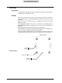
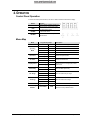
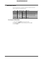
User Manual
TABLE OF CONTENTS
1. Before You Begin ............................................................................. 3
What Is Included ........................................................................................... 3
Unpacking Instructions .................................................................................. 3
Text Conventions .......................................................................................... 3
Icons .............................................................................................................. 3
Safety Notes .................................................................................................. 4
2. Introduction ...................................................................................... 5
Product Overview .......................................................................................... 5
Product Dimensions ...................................................................................... 6
3. Setup ................................................................................................. 7
AC Power ...................................................................................................... 7
Mounting ....................................................................................................... 8
4. Operation .......................................................................................... 9
Control Panel Operation................................................................................ 9
Menu Map ..................................................................................................... 9
Menu Map (hidden) ..................................................................................... 10
Configuration (DMX) ................................................................................... 11
Configuration (Standalone Modes) ............................................................. 11
DMX Channel Assignments and Values ..................................................... 13
5. Technical Information.................................................................... 15
General Maintenance .................................................................................. 15
General Troubleshooting ............................................................................ 16
Returns Procedure ...................................................................................... 17
Claims ......................................................................................................... 17
Contact Information ..................................................................................... 17
DMX Primer .................................................. Error! Bookmark not defined.
6. Technical Specifications ............................................................... 18
Document Information
The information and specifications contained in this document are subject to change without
notice. CHAUVET® assumes no responsibility or liability for any errors or omissions that may
appear in this manual.
© Copyright 2011 CHAUVET®. All rights reserved
Printed in P.R.C.
Electronically published by CHAUVET® in the United States of America
Page 2 of 18
Author
Editor
A. Chiappone
R. Jones
Intimidator™ Spot LED 150 User Manual (Rev. 4)
1. BEFORE YOU BEGIN
What Is Included
·
·
·
·
·
·
·
1 x Intimidator™ Spot LED 150
1 x Mounting Bracket
2 x Mounting Bolts
1 x Safety Eyebolt
1 x Power Cord
1 x Warranty Card
1 x User Manual
Unpacking Instructions
Immediately upon receiving this product, carefully unpack it and check the container in
which you received it. Make sure that you have received all the parts indicated above
and that they are all in good condition. If the material inside the container (this product
and any other accessory included with it) appears damaged from shipping, or if the
container shows signs of mishandling, notify the shipper immediately. In addition,
retain the container and all the packing material for inspection.
See the Claims section in the Technical Information chapter.
Text Conventions
Convention
<Menu>
Meaning
A key to be pressed on the fixture’s control panel
1~512
A range of values
50/60
A set of values of which only one can be chosen
Settings
Menu > Settings
A menu option not to be modified (for example, showing the operating
mode/current status)
A sequence of menu options to be followed
ON
A value to be entered or selected
Icon
Meaning
Icons
This paragraph contains critical installation, configuration, or operation
information. Failure to comply with this information may render the
fixture partially or completely inoperative, cause damage to the fixture,
or cause harm to the user.
This paragraph contains important installation or configuration
information. Failure to comply with this information may prevent the
fixture from functioning correctly.
This paragraph reminds you of useful, although not critical, information.
Product at a Glance
Internal dimmer
Outdoor Use
Sound Activated
DMX
Master/Slave
Intimidator™ Spot LED 150 User Manual (Rev. 4)
P
x
P
P
P
Auto Programs
Auto-ranging Power Supply
Replaceable Fuse
User Serviceable
Duty Cycle
P
P
P
x
x
Page 3 of 18
Safety Notes
Please read the following notes carefully because they include important safety
information about the installation, usage, and maintenance of this product.
Page 4 of 18
·
Keep this User Manual for future consultation. If you sell this product to another
user, be sure that they also receive this document.
·
Always make sure that the voltage of the outlet to which you are connecting this
product is within the range stated on the decal or rear panel of the fixture.
·
This product is for indoor use only! To prevent risk of fire or shock, do not expose
this fixture to rain or moisture.
·
This product is for indoor use. Do not submerge this product.
·
Make sure there are no flammable materials close to the unit while operating.
·
Always install this product in a location with adequate ventilation, at least 20 in (50
cm) from adjacent surfaces.
·
Be sure that no ventilation slots on the unit’s housing are blocked.
·
Always disconnect this product from the power source before cleaning it or
replacing the fuse.
·
Make sure to replace the fuse with another of the same type and rating.
·
If mounting this product overhead, always secure it to a fastening device using a
safety cable.
·
The maximum ambient temperature (Ta) is 104° F (40° C). Do not operate this
product at higher temperatures.
·
In the event of a serious operating problem, stop using the unit immediately.
·
Never try to repair this product. Repairs carried out by unskilled people can lead
to damage or malfunction. Please contact the nearest authorized technical
assistance center.
·
Never connect this product to a dimmer pack.
·
Make sure the power cord is not crimped or damaged.
·
Never disconnect the power cord by pulling or tugging on the cord.
·
Never carry a fixture from the power cord or any moving part. Always use the
hanging/mounting bracket or the handles.
·
Always avoid direct eye exposure to the light source when this fixture is on.
Intimidator™ Spot LED 150 User Manual (Rev. 4)
2. INTRODUCTION
Product Overview
Power in
Power out
DMX out
DMX in
Fuseholder
Intimidator™ Spot LED 150 User Manual (Rev. 4)
Page 5 of 18
Product Dimensions
Page 6 of 18
Intimidator™ Spot LED 150 User Manual (Rev. 4)
3. SETUP
AC Power
This product has an auto-ranging power supply and it can work with an input voltage
range of 100~240 VAC, 50/60 Hz.
To determine the power requirements for a particular fixture, see the label affixed to
the back plate of the fixture or refer to the fixture’s specifications chart. A fixture’s
listed current rating indicates its average current draw under normal conditions.
Always connect this product to a protected circuit (circuit breaker or fuse),
making sure that it has an appropriate electrical ground to avoid the risk of
electrocution or fire.
Never connect this product to a rheostat (variable resistor) or dimmer circuit,
even if the rheostat or dimmer channel serves only as a 0 to 100% switch.
Power Linking
This fixture provides power linking via the Edison outlet located in the back of the unit.
Please see the diagram below for further explanation.
Generic Fixture Housing
1st Fixture
Power Linking
Diagram
2nd Fixture
3rd Fixture
Other fixtures
You can power link up to 11 Intimidator™ Spot LED 150 units on 120 VAC or up
to 20 Intimidator™ Spot LED 150 units on 230 VAC.
The power linking diagram shown above corresponds to the North American
version of this product ONLY! If using this product in other markets, you must
consult with the local CHAUVET® distributor as power linking connectors and
requirements may differ in your country or region.
Intimidator™ Spot LED 150 User Manual (Rev. 4)
Page 7 of 18
Mounting
Orientation
The Intimidator™ Spot LED 150 may be mounted in any position, provided there is
adequate room for ventilation around it.
Rigging
Be sure that the structure onto which you are mounting this product can support its
weight. Please see the “Technical Specifications” section of this manual for weight
information.
Make sure to mount the fixture securely to a rigging point, whether an elevated
platform or a truss.
When rigging this product onto a truss, you should use a mounting clamp of
appropriate weight capacity. The bracket has a 13 mm hole, which is appropriate for
this purpose.
When mounting this product overhead, always use a safety cable.
Before deciding on a location for this product, always make sure that it will be easy to
access the unit for maintenance and programming purposes.
When power linking multiple fixtures, you must always consider the length of the
power linking cable and mount the fixtures close enough for the cable to reach them.
Bottom of fixture
Bracket
attachment
Mounting Diagram
Rubber feet (4)
Safety bolt
attachment
Page 8 of 18
Intimidator™ Spot LED 150 User Manual (Rev. 4)
4. OPERATION
Control Panel Operation
To access the control panel functions, use the four buttons located underneath the display.
Button
Function
Press to find an operation mode or to
back out of the current menu option
Press to scroll down the list of options
or to find a higher value
Press to scroll up the list of options or
to find a lower value
<MODE/ESC>
<UP>
<DOWN>
Press to activate a menu option or a
selected value
<ENTER>
Menu Map
Mode
Programming Steps
DMX Mode
d***
NASL
Operating
Mode
Pan Invert
Tilt Invert
Display Invert
SLoU
FASt
Automatic fast
NStS
SrUn
Sound-active mode
Slave mode
SLAU
SonU
Standard pan
PAN
Inverted pan
rPAN
Standard tilt
tit
Inverted tilt
rtit
dis
Inverted display
rdis
Advanced
11CH
Basic
6CH
Pan 540°
PA54
Pan 360°
PA36
Pan 180°
PA18
Pan Range
Automatic slow
NAFA
Standard display
Personality
Description
d001~512 Selects the DMX starting address
Reverse the pan direction
Reverse the tilt direction
Use this function for hanging the product
upside down
Select the DMX personality
Select the maximum pan range
Tilt 270°
ti27
Tilt Range
Tilt 180°
ti18
Tilt 90°
ti 9
Reset
System reset
rESt
Reset all motors
Load Factory
Defaults
Load default
LoAd
Use this to revert all settings for the fixture
back to the factory-defaults values
Intimidator™ Spot LED 150 User Manual (Rev. 4)
Select the maximum tilt range
Page 9 of 18
Menu Map (hidden)
This fixture has a hidden menu. The purpose of this menu is to adjust the home position
(electronic adjustment) of the attributes listed below.
Mode
Programming Steps
Description
Pan adjustment
P***
P000~255
Adjust the pan home position
Tilt adjustment
t***
t000~255
Adjust the tilt home position
Gobo wheel
adjustment
G***
G000~255
Adjust the gobo wheel home position
Color wheel
adjustment
C***
C000~255
Adjust he color wheel home position
LED dimmer
threshold
d***
d000~255
Adjust the LED dimming threshold
(minimum)
Accessing the Hidden Menu
1) Press and hold <MODE/ESC> for at least 10 seconds.
2) Use <UP> or <DOWN> to input the following access code: 2323.
3) Press <ENTER>.
Page 10 of 18
Intimidator™ Spot LED 150 User Manual (Rev. 4)
Configuration (DMX)
Set this product in DMX mode to control it with a DMX controller.
1) Connect this product to a suitable power outlet.
2) Turn this product on.
3) Connect a DMX cable from the DMX output of the DMX controller to the DMX
input socket of this product.
Starting Address
When selecting a starting DMX address, always consider the number of DMX
channels the selected DMX mode uses. If you choose a starting address that is too
high, you could restrict the access to some of the fixture’s channels.
The Intimidator™ Spot LED 150 uses up to 11 DMX channels in the advanced
personality, which defines the highest configurable address to 502.
If you are not familiar with the DMX protocol, you may refer to the “DMX Primer”
section in the “Technical Information” chapter.
To select the starting address, do the following:
1) Press <MODE/ESC> repeatedly until d*** shows on the display.
2) Press <ENTER>.
3) Use <UP> or <DOWN> to select the starting address.
4) Press <ENTER>.
Configuration (Standalone Modes)
Set this product in one of the standalone modes to control it without a DMX controller.
1) Connect this product to a suitable power outlet.
2) Turn this product on.
Sound Active Mode
To enable the Sound Active mode, do the following:
1) Press <MODE/ESC> repeatedly until one of the following shows on the display:
NASL, NAFA, NStS, SLAU.
2) Use <UP> or <DOWN> to select NStS.
3) Turn the music on.
4) Press <ENTER>.
The fixture will only respond to the low frequencies of the music (bass and
drums).
Automatic Mode
Never connect a fixture that is operating in any standalone mode, whether
Static, Automatic, or Sound to a DMX string connected to a DMX controller.
This is because fixtures in standalone mode may transmit DMX signals that
could interfere with the DMX signals from the controller.
To enable the Automatic Mode, follow the instructions below:
1) Press <MODE/ESC> repeatedly until one of the following shows on the display:
NASL, NAFA, NStS, SLAU.
2) Use <UP> or <DOWN> to select NAFA (fast) or NASL (slow).
4) Press <ENTER>.
Intimidator™ Spot LED 150 User Manual (Rev. 4)
Page 11 of 18
Master/Slave Mode
This mode allows a single Intimidator™ Spot LED 150 unit (the “master”) to control
the actions of one or more Intimidator™ Spot LED 150 units (the “slaves”) without the
need of a DMX controller. The master unit will be set to operate in either Automatic or
Sound Active mode, while the slave units will be set to operate in Slave Mode. Once
set and connected, the slave units will operate in unison with the master unit.
Configure the units as indicated below.
Slave units:
1) Press <MODE/ESC> repeatedly until one of the following shows on the display:
NASL, NAFA, NStS, SLAU.
2) Press <ENTER> to accept.
3) Set the DMX address to “001”, as previously explained.
5) Connect the DMX input of the first slave unit to the DMX output of the master unit.
6) Connect the DMX input of the subsequent slave units to the DMX output of the
previous slave unit.
7) Finish setting and connecting all the slave units.
Master unit:
1) Set the master unit to operate in either Automatic or Sound mode, as previously
indicated.
2) Make the master unit the first unit in the DMX daisy chain.
Page 12 of 18
·
Configure all the slave units before connecting the master unit to the DMX
daisy chain.
·
Never connect a DMX controller to a DMX string configured for Master/Slave
operation because it may interfere with the signals from the master unit.
·
Do not connect more than 31 slave units to the master unit.
Intimidator™ Spot LED 150 User Manual (Rev. 4)
DMX Channel Assignments and Values
11-CH
Channel
Function
Value
Setting
1
Pan
000 ó 255
0~540°
2
Tilt
000 ó 255
0~270°
3
Pan fine
000 ó 255
0~3°
4
Tilt fine
000 ó 255
0~3°
5
Pan/tilt speed
000 ó 255
Fast~slow
6
Color
000 ó 005
006 ó 011
012 ó 017
018 ó 023
024 ó 029
030 ó 035
036 ó 041
042 ó 047
048 ó 053
054 ó 063
064 ó 069
070 ó 075
076 ó 081
082 ó 087
088 ó 093
094 ó 099
100 ó 105
106 ó 111
112 ó 117
118 ó 127
128 ó 191
192 ó 255
Open (white)
1 (yellow)
2 (magenta)
3 (green)
4 (red)
5 (cyan)
6 (orange)
7 (blue)
8 (light green)
9 (light red)
White/yellow (split colors)
Yellow/magenta (split colors)
Magenta/green (split colors)
Green/red (split colors)
Red/cyan (split colors)
Cyan/orange (split colors)
Orange/blue (split colors)
Blue/light green (split colors)
Light green/light red (split colors)
Light red/white (split colors)
Rotate clockwise (slow~fast)
Rotate counter-clockwise (slow~fast)
7
Shutter
000 ó 003
004 ó 007
008 ó 215
216 ó 255
Blackout
Open
Strobe (0.5~20 Hz)
Open
8
Dimmer
000 ó 255
0~100%
Gobo
000 ó 005
006 ó 011
012 ó 017
018 ó 023
024 ó 029
030 ó 035
036 ó 041
042 ó 047
048 ó 053
054 ó 063
064 ó 073
074 ó 079
080 ó 085
086 ó 091
092 ó 097
098 ó 103
104 ó 109
110 ó 115
116 ó 121
122 ó 127
128 ó 191
192 ó 255
Open
Gobo 1
Gobo 2
Gobo 3
Gobo 4
Gobo 5
Gobo 6
Gobo 7
Gobo 8
Gobo 9
Gobo 1 (gobo shake)
Gobo 2 (gobo shake)
Gobo 3 (gobo shake)
Gobo 4 (gobo shake)
Gobo 5 (gobo shake)
Gobo 6 (gobo shake)
Gobo 7 (gobo shake)
Gobo 8 (gobo shake)
Gobo 9 (gobo shake)
Open
Rotate clockwise (slow~fast)
Rotate counter-clockwise (slow~fast)
Control
000 ó 007
008 ó 027
028 ó 047
048 ó 067
068 ó 087
088 ó 107
108 ó 127
128 ó 147
148 ó 167
168 ó 187
188 ó 207
208 ó 227
228 ó 247
248 ó 255
No function
Enable pan/tilt move-in-black
Enable gobo move-in-black
Disable pan/tilt/gobo move-in-black
Enable color move-in-black
Disable pan/tilt/color move-in-black
Disable gobo/color move-in-black
Disable pan/tilt/gobo/color move-in-black
Reset pan
Reset tilt
Reset color
Reset gobo
Reset all
No function
Pan/tilt Movement macros
000 ó 007
008 ó 023
024 ó 039
040 ó 055
056 ó 071
No function
Automatic movement 1
Automatic movement 2
Automatic movement 3
Automatic movement 4
9
10
11
Continues on the next page
Intimidator™ Spot LED 150 User Manual (Rev. 4)
Page 13 of 18
Continued from previous page
Channel
11
Function
Value
Pan/tilt Movement macros
072 ó 087
088 ó 103
104 ó 119
120 ó 135
136 ó 151
152 ó 167
168 ó 183
184 ó 199
200 ó 215
216 ó 231
232 ó 247
248 ó 255
Setting
Automatic movement 5
Automatic movement 6
Automatic movement 7
Automatic movement 8
Sound-active movement 1
Sound-active movement 2
Sound-active movement 3
Sound-active movement 4
Sound-active movement 5
Sound-active movement 6
Sound-active movement 7
Sound-active movement 8
6-CH
Channel
Value
Setting
1
Pan
000 ó 255
0~540°
2
Tilt
000 ó 255
0~270°
3
Color
000 ó 005
006 ó 011
012 ó 017
018 ó 023
024 ó 029
030 ó 035
036 ó 041
042 ó 047
048 ó 053
054 ó 063
064 ó 069
070 ó 075
076 ó 081
082 ó 087
088 ó 093
094 ó 099
100 ó 105
106 ó 111
112 ó 117
118 ó 127
128 ó 191
192 ó 255
Open (white)
1 (yellow)
2 (magenta)
3 (green)
4 (red)
5 (cyan)
6 (orange)
7 (blue)
8 (light green)
9 (light red)
White/yellow (split colors)
Yellow/magenta (split colors)
Magenta/green (split colors)
Green/red (split colors)
Red/cyan (split colors)
Cyan/orange (split colors)
Orange/blue (split colors)
Blue/light green (split colors)
Light green/light red (split colors)
Light red/white (split colors)
Rotate clockwise (slow~fast)
Rotate counter-clockwise (slow~fast)
4
Shutter
000 ó 003
004 ó 007
008 ó 215
216 ó 255
Blackout
Open
Strobe (0.5~20 Hz)
Open
5
Dimmer
000 ó 255
0~100%
Gobo
000 ó 005
006 ó 011
012 ó 017
018 ó 023
024 ó 029
030 ó 035
036 ó 041
042 ó 047
048 ó 053
054 ó 063
064 ó 073
074 ó 079
080 ó 085
086 ó 091
092 ó 097
098 ó 103
104 ó 109
110 ó 115
116 ó 121
122 ó 127
128 ó 191
192 ó 255
Open
Gobo 1
Gobo 2
Gobo 3
Gobo 4
Gobo 5
Gobo 6
Gobo 7
Gobo 8
Gobo 9
Gobo 1 (gobo shake)
Gobo 2 (gobo shake)
Gobo 3 (gobo shake)
Gobo 4 (gobo shake)
Gobo 5 (gobo shake)
Gobo 6 (gobo shake)
Gobo 7 (gobo shake)
Gobo 8 (gobo shake)
Gobo 9 (gobo shake)
Open
Rotate clockwise (slow~fast)
Rotate counter-clockwise (slow~fast)
6
Function
1
1
Page 14 of 18
2
2
3
3
4
4
5
5
6
6
7
7
8
8
9
9
Intimidator™ Spot LED 150 User Manual (Rev. 4)
5. TECHNICAL INFORMATION
General Maintenance
Dust build up reduces light output performance and can cause overheating. This can
lead to reduction of the light source’s life and/or mechanical wear. To maintain
optimum performance and minimize wear, you should clean your lighting fixtures at
least twice a month. However, be aware that usage and environmental conditions
could be contributing factors to increase the cleaning frequency.
To clean this fixture, follow the instructions below:
·
Unplug the fixture from power.
·
Wait until the fixture is cold.
·
Use a vacuum (or dry compressed air) and a soft brush to remove dust collected
on the external surface/vents.
·
Clean all external optics with a mild soap solution, ammonia-free glass cleaner, or
isopropyl alcohol.
·
Apply the solution directly to a soft, lint free cotton cloth or a lens cleaning tissue.
·
Softly drag any dirt or grime to the outside of the external optics.
·
Gently polish the external optics until they are free of haze and lint.
Always dry the external optics carefully after cleaning them.
Do not spin the cooling fans using compressed air because you could damage
them.
Intimidator™ Spot LED 150 User Manual (Rev. 4)
Page 15 of 18
General Troubleshooting
Symptom
Circuit breaker
or fuse keeps
blowing
Product does not
power up
Fixture does not
respond to DMX
Intermittent DMX
Problems
Possible Cause
Possible Action
Excessive load on the circuit
Make sure that the total load does
not exceed 80% of the breaker or
fuse nominal current
Short circuit along the power lines
Check the power lines and power
cords
No energy on power outlet
Check power outlet
Change to another outlet
Loose or damaged power cord
Check the power cord
Blown fuse
Replace blown fuse with a good
one of the same type and rating
Internal problem
Send product for repair
Wrong starting address on the
fixture
Set the correct starting address on
the fixture
Use the right fader(s) on the
controller
Wrong DMX personality on the
fixture
Set the correct DMX fixture’s
personality
Assign the faders accordingly
Wrong operating mode set on the
fixture
Change the fixture settings
Loose or damaged DMX cable
Check the DMX cable before the
faulty unit
Internal problem
Send product for repair
Signal cables are not DMX
compatible
Replace non DMX cables with true
DMX cables
Interference with AC or radio
signals
Keep DMX cables away from AC
wires or radio equipment
DMX cable too long
Install an optically coupled DMX
amplifier right before the fixture with
intermittent problems
Too many fixtures connected
Install an optically coupled DMX
amplifier after unit #32
Terminator not connected
Install a terminator, as indicated in
the “DMX Primer” section.
If you still experience problems after trying the above solutions, contact
CHAUVET® Technical Support.
Page 16 of 18
Intimidator™ Spot LED 150 User Manual (Rev. 4)
Returns Procedure
The user must send the merchandise prepaid, in the original box, and with its original
packing and accessories. CHAUVET® will not issue call tags.
Call CHAUVET® and request a Return Merchandise Authorization Number (RMA #)
before shipping the fixture. Be prepared to provide the model number, serial number,
and a brief description of the cause for the return.
The user must clearly label the package with an RMA #. CHAUVET® will refuse any
product returned without an RMA #.
DO NOT write the RMA # directly on the box. Instead, write it on a properly
affixed label.
Once you have received the RMA #, please include the following information on a
piece of paper inside the box:
·
Your name
·
Your address
·
Your phone number
·
The RMA #
·
A brief description of the problem
Be sure to pack the fixture properly. Any shipping damage resulting from inadequate
packaging will be the customer’s responsibility. As a suggestion, proper UPS packing
or double-boxing is always a safe method to use.
CHAUVET® reserves the right to use its own discretion to repair or replace
returned product(s).
Claims
The carrier is responsible for any damage incurred during shipping to this product or
any part that shipped with it. Therefore, if the received merchandise appears to have
damages caused during shipping, the customer must submit the damage report and
any related claims with the carrier, not CHAUVET®. The customer must submit the
report upon reception of the damaged merchandise. Failure to do so in a timely
manner may invalidate the customer’s claim with the carrier.
For other issues such as missing components or parts, damage not related to
shipping, or concealed damage, the customer must make claims to CHAUVET®
within seven (7) days of receiving the merchandise.
Contact Information
World Headquarters
United Kingdom & Ireland
CHAUVET®
CHAUVET® Europe Ltd.
General Information
Address:
Voice:
Fax:
Toll free:
General Information
5200 NW 108th Avenue
Sunrise, FL 33351
(954) 929-1115
(954) 929-5560
(800) 762-1084
Technical Support
Voice:
Fax:
Email:
(954) 929-1115 (Press 4)
(954) 756-8015
[email protected]
World Wide Web
Voice:
Fax:
Unit 1C
Brookhill Road Industrial Estate
Pinxton, Nottingham, UK
NG16 6NT
+44 (0)1773 511115
+44 (0)1773 511110
Technical Support
Email:
[email protected]
World Wide Web
www.chauvetlighting.com
Intimidator™ Spot LED 150 User Manual (Rev. 4)
Address:
www.chauvetlighting.co.uk
Page 17 of 18
6. TECHNICAL SPECIFICATIONS
Dimensions and
Weight
Length
Width
Height
Weight
8.1 in (205 mm)
8.3 in (211 mm)
11.5 in (291 mm)
9.3 lbs (4.2 kg)
Note: Dimensions in inches rounded to the nearest decimal digit.
Power
Light Source
Photo Optic
Thermal
DMX
Ordering
Page 18 of 18
Power Supply Type
Range
Voltage Selection
Switching (internal)
100~240 V, 50/60 Hz
Auto-ranging
Parameter
120 V, 60 Hz
230 V, 50 Hz (Europe only)
Consumption
54 W (0.7 A)
91 W (0.4 A)
Power I/O
Input
Output
Connectors
IEC
Edison
Cord plug
Edison
N/A
Type
Power
Lifespan
LED
25 W (1.5 A)
50,000 hours
Color
Quantity
LED Drive Current
White
1
3.6 mA
Parameter
Narrow Lenses
Illuminance @ 1 m
14,200 lux
Illuminance @ 2 m
2,714 lux
Beam angle
15º
Maximum External Temp.
Cooling System
104° F (40° C)
Fan cooled
I/O Connectors
Connector Type
Channel Range
3-pin XLR
Sockets
6, 11
Item No.
Item Name
Item Code
INTIMSPOTLED150
Intimidator™ Spot LED 150
08010176
Intimidator™ Spot LED 150 User Manual (Rev. 4)