1
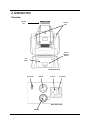
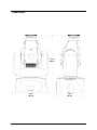
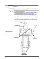
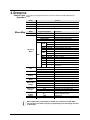
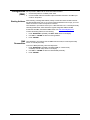
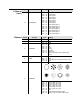
User Manual
TABLE OF CONTENTS
1. Before You Begin ...........................................................................................................3
What Is Included ......................................................................................................................... 3
Unpacking Instructions ................................................................................................................ 3
Claims ................................................................................................................................................. 3
Text Conventions ........................................................................................................................ 3
Symbols ...................................................................................................................................... 3
Disclaimer ................................................................................................................................... 3
Product at a Glance..................................................................................................................... 4
Safety Notes ............................................................................................................................... 4
2. Introduction ....................................................................................................................5
Overview ..................................................................................................................................... 5
Dimensions ................................................................................................................................. 6
3. Setup ...............................................................................................................................7
AC Power .................................................................................................................................... 7
Fuse Replacement ............................................................................................................................... 7
Mounting ..................................................................................................................................... 8
Orientation ........................................................................................................................................... 8
Rigging ................................................................................................................................................ 8
4. Operation ........................................................................................................................9
Control Panel Operation .............................................................................................................. 9
Menu Map ................................................................................................................................... 9
Configuration (DMX).................................................................................................................. 10
Starting Address ................................................................................................................................ 10
DMX Personalities.............................................................................................................................. 10
DMX Channel Modes, Assignments, and Values ....................................................................... 11
11-Channel ........................................................................................................................................ 11
11-Channel (cont.) ............................................................................................................................. 12
6-Channel .......................................................................................................................................... 12
Configuration (Standalone) ........................................................................................................ 13
Sound-Active Mode ............................................................................................................................ 13
Automatic Mode ................................................................................................................................. 13
NSti Operating Mode.......................................................................................................................... 13
NSti Operating Mode (cont.) ............................................................................................................... 14
IRC Operation.................................................................................................................................... 15
Manual Pan/Tilt Operation .................................................................................................................. 16
Pan/Tilt Angle Range ......................................................................................................................... 16
Display Orientation............................................................................................................................. 16
Temperature Display .......................................................................................................................... 16
Reset Software .................................................................................................................................. 16
Load Factory Defaults ........................................................................................................................ 16
Master/Slave Mode ............................................................................................................................ 17
5. Technical Information ..................................................................................................18
Product Maintenance ................................................................................................................ 18
6. Technical Specifications ..............................................................................................19
Returns ..................................................................................................................................... 20
Contact Us ................................................................................................................................ 20
Page 2 of 20
Intimidator™ Spot 100 IRC User Manual
1. BEFORE YOU BEGIN
What Is
Included
Unpacking
Instructions
Claims
Text
Conventions
Symbols
·
·
Intimidator™ Spot 100 IRC
Hanging Bracket with Mounting
Hardware
·
·
·
Power Cord
Warranty Card
Quick Reference Guide
Carefully unpack the product immediately and check the container to make sure all the
parts are in the package and are in good condition.
If the box or the contents (the product and included accessories) appear damaged from
shipping, or show signs of mishandling, notify the carrier immediately, not CHAUVET®.
Failure to report damage to the carrier immediately may invalidate your claim. In
addition, keep the box and contents for inspection.
For other issues, such as missing components or parts, damage not related to shipping,
or concealed damage, file a claim with CHAUVET® within 7 days of delivery.
Convention
1—512
50/60
Settings
Menu > Settings
<ENTER>
ON
Symbol
Meaning
A range of values
A set of values of which only one can be chosen
A menu option not to be modified
A sequence of menu options to be followed
A key to be pressed on the product’s control panel
A value to be entered or selected
Meaning
Critical installation, configuration, or operation information. Not
following these instructions may make the product not work, cause
damage to the product, or cause harm to the operator.
Important installation or configuration information. The product
may not function correctly if this information is not used.
Useful information.
Disclaimer
The information and specifications contained in this User Manual are subject to change
without notice. CHAUVET® assumes no responsibility or liability for any errors or
omissions, and reserves the right to revise or recreate this manual at any time.
Download the latest version from www.chauvetlighting.com.
© Copyright 2013 CHAUVET®. All rights reserved.
Electronically published by CHAUVET® in the United States of America.
Author
Date
Editor
Date
A. Leon
07/12/13
T. Yeago
07/15/13
Intimidator™ Spot 100 IRC User Manual
Page 3 of 20
Product at a
Glance
Use on Dimmer
Outdoor Use
Sound-Activated
DMX
Master/Slave
Safety Notes
Auto Programs
Auto-ranging Power Supply
Replaceable Fuse
User-Serviceable
P
P
P
x
These notes include important information about the mounting, usage, and maintenance
of this product; read before using the product.
·
·
·
·
·
·
·
·
·
·
·
·
·
·
·
·
·
·
·
·
Page 4 of 20
x
x
P
P
P
Always connect the product to a grounded circuit to avoid the risk of electrocution.
Always disconnect the product from the power source before cleaning or replacing
the fuse.
Avoid direct eye exposure to the light source while the product is on.
Make sure the power cord is not crimped or damaged.
Never disconnect the product from power by pulling or tugging on the cord.
If mounting the product overhead, always secure to a fastening device using a
safety cable.
Make sure there are no flammable materials close to the product when operating.
Do not touch the product’s housing when operating because it may be very hot.
Always make sure that the voltage of the outlet to which you are connecting the
product is within the range stated on the decal or rear panel of the product.
The product is for indoor use only! (IP20) To prevent risk of fire or shock, do not
expose the product to rain or moisture.
Always install the product in a location with adequate ventilation, at least 20 in
(50 cm) from adjacent surfaces.
Be sure that no ventilation slots on the product’s housing are blocked.
Never connect the product to a dimmer.
Make sure to replace the fuse with another of the same type and rating.
Never carry the product from the power cord or any moving part. Always use the
hanging/mounting bracket.
The maximum ambient temperature (Ta) is 104 °F (40 °C). Do not operate the
product at higher temperatures.
In the event of a serious operating problem, stop using the product immediately.
Never try to repair the product. Repairs carried out by unskilled people can lead to
damage or malfunction. Contact the nearest authorized technical assistance center.
This product is not intended for permanent installation.
Keep this User Manual for future use. If you sell the product to another user, be
sure to give this document to the next owner.
Intimidator™ Spot 100 IRC User Manual
2. INTRODUCTION
Overview
Focusing
Lens
Moving
Yoke
Control
Panel and
Buttons
IRC
Sensor
Front Panel View
Safety Loop
DMX In
Power In
Fuse Holder
Back Panel View
DMX Out
Intimidator™ Spot 100 IRC User Manual
Page 5 of 20
Dimensions
11.6 in
295 mm
7.8 in
198 mm
Page 6 of 20
5.8 in
148 mm
Intimidator™ Spot 100 IRC User Manual
3. SETUP
AC Power
The Intimidator™ Spot 100 IRC has an auto-ranging power supply and it can work with
an input voltage range of 100~240 VAC, 50/60 Hz.
To determine the product’s power requirements (circuit breaker, power outlet, and
wiring), use the current value listed on the label affixed to the product’s back panel, or
refer to the product’s specifications chart. The listed current rating indicates the
product’s average current draw under normal conditions.
Always connect the product to a protected circuit (circuit breaker or fuse). Make
sure the product has an appropriate electrical ground to avoid the risk of
electrocution or fire.
Never connect the product to a rheostat (variable resistor) or dimmer circuit, even
if the rheostat or dimmer channel serves only as a 0—100% switch.
Fuse
Replacement
Disconnect the product from power before replacing the fuse.
1.
2.
3.
4.
5.
6.
Disconnect the product from power.
Wedge the tip of a flat-head screwdriver into the slot of the fuse holder.
Pry the fuse holder out of the housing.
Remove the blown fuse from the holder.
Replace with a fuse of the exact same type and rating.
Insert the fuse holder back in place and reconnect power.
Installed fuse
(held by plastic clip)
Safety cap
Spare fuse holder
(inside safety cap)
A spare fuse is not included; however, the safety cap has room for a spare.
Always replace a blown fuse with another of the same type and rating.
Intimidator™ Spot 100 IRC User Manual
Page 7 of 20
Mounting
Before mounting the product, read and follow the safety recommendations indicated in
the Safety Notes.
Orientation
The Intimidator™ Spot 100 IRC may be mounted in any position; however, make sure
adequate ventilation is provided around the product.
Rigging
·
Before deciding on a location, always make sure there is easy access to the product
for maintenance and programming.
·
Make sure that the structure or surface onto which you are mounting the product
can support the product’s weight (see the Technical Specifications).
·
When mounting the product overhead, always use a safety cable. Mount the
product securely to a rigging point, such as an elevated platform or a truss.
·
When rigging the product onto a truss, you should use a mounting clamp of
appropriate weight capacity. The brackets have a 13-mm hole, which is appropriate
for this purpose.
·
The rubber feet also serve as floor supports. When mounting the product on the
floor, make sure that the product and cables are away from people and vehicles.
Mounting Clamp
Hanging/Mounting
Bracket
Safety Cable
Mounting Diagram
Rubber Feet (x4)
for floor mounting
Page 8 of 20
Safety Loop
Intimidator™ Spot 100 IRC User Manual
4. OPERATION
Control Panel
Operation
To access the control panel functions, use the four buttons located underneath the
display.
Button
Function
<MODE/ESC> Selects an operation mode or backs out of the current menu option
<UP>
Menu Map
Scrolls up the list of options or selects a higher value
<DOWN>
Scrolls down the list of options or selects a lower value
<ENTER>
Activates a menu option or a selected value
Mode
DMX Mode
Operating
Mode
Pan
Tilt
Display
Channel
Mode
Manual Pan
Range
Manual Tilt
Range
Temperature
Display
Reset
Load
Programming Steps
d001—d512
SLAV (Son)
NASL (SLoU)
NAFA (FASt)
NStS (Srun)
Soun
NodE
Auto
NoSP 000—255
NoSE
00—09
NoPr
01—09
on
LEd
oFF
NSti
diMM 000—255
SHut
00—20
Gobo
00—09
GoSP 000—100
CoLr
00—09
Description
Selects the DMX starting address
Slave operating mode
Automatic mode, slow program
Automatic mode, fast program
Sound-Active mode
Sound-Active movement macro
Automatic movement macro
Movement macro speed, fast to slow
Sound sensitivity, high to low
Movement macro 1—9
LED on
LED off
Dimmer, 0—100%
Strobe, 0—20 Hz
Selects gobo
Sets gobo cycle effect speed, slow to fast
Selects color
Sets color cycling rainbow effect speed,
CoSP 000—100
slow to fast
PAn
Normal pan operation
rPAn
Inverse pan operation
tit
Normal tilt operation
rtit
Inverse tilt operation
diS
Normal display
rdiS
Inverse display
6-CH
Selects the 6-channel DMX personality
11CH
Selects the 11-channel DMX personality
PA54
Selects the 540° pan angle range
PA36
Selects the 360° pan angle range
PA18
Selects the 180° pan angle range
ti27
Selects the 270° tilt angle range
ti18
Selects the 180° tilt angle range
ti 9
Selects the 90° tilt angle range
tC__
Displays LED temperature
rESt
LoAd
Resets fixture
Load factory defaults
While in NSti mode, the Intimidator™ 100 IRC also responds to the IRC. When
using the IRC in this mode, changes in programming levels and settings will show
on the display.
Intimidator™ Spot 100 IRC User Manual
Page 9 of 20
Configuration
(DMX)
Starting Address
Set the product in DMX mode to control with a DMX controller.
1. Connect the product to a suitable power outlet.
2. Connect a DMX cable from the DMX output of the DMX controller to the DMX input
socket on the product.
When selecting a starting DMX address, always consider the number of DMX channels
the selected DMX mode uses. If you choose a starting address that is too high, you could
restrict the access to some of the product’s channels.
The Intimidator™ Spot 100 IRC uses up to 11 DMX channels in its 11-channel personality
name/single DMX mode, which defines the highest configurable address to 502.
If unfamiliar with DMX, download the DMX Primer from www.chauvetlighting.com.
To select the starting address, do the following:
1. Press <MODE/ESC> repeatedly until d001—d512 shows on the display.
2. Use <UP> or <DOWN> to select the starting address.
3. Press <ENTER>.
DMX
Personalities
Page 10 of 20
The Intimidator™ Spot 100 IRC has two DMX Channel modes, a 6-channel personality
and an 11-channel personality.
To choose a DMX personality, follow the steps below:
1. Press <MODE/ESC> repeatedly until either 11CH (11-channel mode)
or 6-CH (6-channel mode) shows on the display.
2. Use <UP> or <DOWN> to select the desired DMX personality.
3. Press <ENTER>.
Intimidator™ Spot 100 IRC User Manual
DMX Channel Modes, Assignments, and Values
11-Channel
Channel
Function
1
2
3
4
5
Pan
Tilt
Fine Pan
Fine Tilt
Speed
6
Color Wheel
Value
Setting
000 ó
000 ó
000 ó
000 ó
000 ó
000 ó
016 ó
032 ó
048 ó
064 ó
080 ó
096 ó
112 ó
128 ó
192 ó
255
255
255
255
255
015
031
047
063
079
095
111
127
191
255
0 to 540°
0 to 270°
Fine control of panning
Fine control of tilting
Pan/Tilt speed (fast to slow)
White
Blue
Yellow
Pink
Green
Orange
Light blue
Orange red
Color cycling rainbow with increasing speed
Reverse color cycling rainbow with increasing
speed
003
007
215
255
Closed
Open
Strobe effect with increasing speed (0 to 20 Hz)
Open
7
Shutter
000 ó
004 ó
008 ó
216 ó
8
Dimmer
000 ó 255 0 to 100%
9
Gobo Wheel
064 ó
072 ó
080 ó
088 ó
096 ó
104 ó
112 ó
120 ó
128 ó
192 ó
071
079
087
095
103
111
119
127
191
255
Gobo 7 shake, slow to fast
Gobo 6 shake, slow to fast
Gobo 5 shake, slow to fast
Gobo 4 shake, slow to fast
Gobo 3 shake, slow to fast
Gobo 2 shake, slow to fast
Gobo 1 shake, slow to fast
Open
Cycle effect with increasing speed
Reverse cycle effect with increasing speed
000 ó
008 ó
028 ó
048 ó
007
027
047
067
No function
Blackout while panning/tilting
Blackout while moving gobo wheel
Disable blackout while panning/tilting/moving
gobo wheel
Blackout while moving color wheel
Disable blackout while panning/tilting/moving
color wheel
Disable blackout while moving gobo/color wheel
Disable blackout while moving all options
Reset pan
Reset tilt
Reset color wheel
Reset gobo wheel
Reset all channels
No function
068 ó 087
088 ó 107
10
Control Function
Intimidator™ Spot 100 IRC User Manual
108 ó
128 ó
148 ó
168 ó
188 ó
208 ó
228 ó
248 ó
127
147
167
187
207
227
247
255
Page 11 of 20
11-Channel
(cont.)
Channel
11
6-Channel
Function
Auto Programs
Channel
1
2
3
Function
Pan
Tilt
Color Wheel
Value
000 ó
008 ó
024 ó
040 ó
056 ó
072 ó
088 ó
104 ó
120 ó
136 ó
152 ó
168 ó
184 ó
200 ó
216 ó
232 ó
248 ó
Value
No function
Auto Program 1
Auto Program 2
Auto Program 3
Auto Program 4
Auto Program 5
Auto Program 6
Auto Program 7
Auto Program 8
Sound-Active program 1
Sound-Active program 2
Sound-Active program 3
Sound-Active program 4
Sound-Active program 5
Sound-Active program 6
Sound-Active program 7
Sound-Active program 8
Setting
000 ó 255 0 to 540°
000 ó 255 0 to 270°
000 ó
016 ó
032 ó
048 ó
064 ó
080 ó
096 ó
112 ó
128 ó
192 ó
015
031
047
063
079
095
111
127
191
255
White
Blue
Yellow
Pink
Green
Orange
Light blue
Orange red
Color cycling rainbow with increasing speed
Reverse color cycling rainbow with increasing
speed
003
007
215
255
Closed
Open
Strobe effect with increasing speed (0 to 20 Hz)
Open
4
Shutter
000 ó
004 ó
008 ó
216 ó
5
Dimmer
000 ó 255 0 to 100%
6
Gobo Wheel
064 ó
072 ó
080 ó
088 ó
096 ó
104 ó
112 ó
120 ó
128 ó
192 ó
Page 12 of 20
007
023
039
055
071
087
103
119
135
151
167
183
199
215
231
247
255
Setting
071
079
087
095
103
111
119
127
191
255
Gobo 7 shake, slow to fast
Gobo 6 shake, slow to fast
Gobo 5 shake, slow to fast
Gobo 4 shake, slow to fast
Gobo 3 shake, slow to fast
Gobo 2 shake, slow to fast
Gobo 1 shake, slow to fast
Open
Cycle effect with increasing speed
Reverse cycle effect with increasing speed
Intimidator™ Spot 100 IRC User Manual
Configuration
(Standalone)
Set the product in one of the standalone modes to control without a DMX controller.
1. Connect the product to a suitable power outlet.
Never connect a product that is operating in any standalone mode (Static,
Automatic, or Sound-Active) to a DMX string connected to a DMX controller.
Products in standalone mode may transmit DMX signals that could interfere with
the DMX signals from the controller.
Sound-Active
Mode
To enable the Sound-Active mode, do the following:
1. Press <MODE/ESC> repeatedly until one of the following Operating modes shows
on the display: SLAV, NASL, NAFA, NStS, NSti.
2. Use <UP> or <DOWN> to select NStS.
3. Press <ENTER> and Srun shows on the display.
The product will only respond to low frequencies of music (bass and drums).
Automatic Mode
NSti Operating
Mode
To enable the Automatic mode, follow the instructions below:
1. Press <MODE/ESC> repeatedly until one of the following shows on the display:
SLAV, NASL, NAFA, NStS, NSti.
2. Use <UP> or <DOWN> to select NASL (slow program) or NAFA (fast program).
3. Press <ENTER> and SLoU (slow program) or FASt (fast program) shows on the
display.
To enable the NSti Operating mode, do the following:
1. Press <MODE/ESC> repeatedly until one of the following shows on the display:
SLAV, NASL, NAFA, NStS, NSti.
2. Use <UP> or <DOWN> to select NSti.
3. Press <ENTER> and NodE, NoSP, NoSE, NoPr, LEd, diMM, SHut, Gobo, GoSP,
CoLr, or SoSP show on the display.
4. Use <UP> or <DOWN> to select the desired option as follows:
To select from the movement macro options:
1. Select NodE and press <ENTER>.
2. Use <UP> or <DOWN> to select Soun (Sound-Active) or Auto (Automatic).
3. Press <ENTER>.
To select the movement macro speed:
1. Select NoSP and press <ENTER>.
2. Use <UP> or <DOWN> to select 000—255.
3. Press <ENTER>.
To select the sound sensitivity:
1. Select NoSE and press <ENTER>.
2. Use <UP> or <DOWN> to select 00—09.
3. Press <ENTER>.
To select the movement macro:
1. Select NoPr and press <ENTER>.
2. Use <UP> or <DOWN> to select 01—09.
Note: No macro is selected if you choose 00.
3. Press <ENTER>.
Intimidator™ Spot 100 IRC User Manual
Page 13 of 20
NSti Operating
Mode (cont.)
To turn the LED on or off:
1. Select LEd and press <ENTER>.
2. Use <UP> or <DOWN> to select on or oFF.
3. Press <ENTER>.
For dimmer control:
1. Select diMM and press <ENTER>.
2. Use <UP> or <DOWN> to select 000—255 (0—100%).
3. Press <ENTER>.
To set the shutter speed:
1. Select SHut and press <ENTER>.
2. Use <UP> or <DOWN> to select 0—20 (0—20 Hz).
3. Press <ENTER>.
To select the gobo:
1. Select Gobo and press <ENTER>.
2. Use <UP> or <DOWN> to select 0—09.
3. Press <ENTER>.
To set the gobo cycle effect speed:
1. Select GoSP and press <ENTER>.
2. Use <UP> or <DOWN> to select 000—100.
3. Press <ENTER>.
To select the color:
1. Select CoLr and press <ENTER>.
2. Use <UP> or <DOWN> to select 00—09.
3. Press <ENTER>.
To set the color cycling rainbow effect speed:
1. Select CoSP and press <ENTER>.
2. Use <UP> or <DOWN> to select 000—100 (slow to fast).
3. Press <ENTER>.
While in NSti mode, the Intimidator™ 100 IRC also responds to the IRC. When
using the IRC in this mode, changes in programming levels and settings will show
on the display.
Page 14 of 20
Intimidator™ Spot 100 IRC User Manual
IRC Operation
Note: Make sure to point the IRC directly at the receiver.
The following IRC buttons are used with the Intimidator™ Spot 100 IRC:
·
·
·
·
·
·
·
·
·
·
·
·
·
<BLACKOUT> - turns LED on/off
<AUTO> - activates Automatic mode
<SOUND> - activates Sound-Active mode
<STROBE> - strobing (0–20 Hz)
<SPEED> - changes from fast to slow movement
<SENSITIVITY> - adjusts sound sensitivity
<%> - master dimmer
<MANUAL> - changes gobo on gobo wheel
<FADE/SNAP> - changes color on color wheel
<R> - activates color wheel scroll
<G> - activated gobo wheel scroll
<B> - activates random gobo and color combinations
<+> (plus) - increases strobe/sensitivity/dimmer/color wheel scroll/gobo
wheel scroll/random gobo and color combinations
·
<-> (minus) - decreases strobe/sensitivity/dimmer/color wheel scroll/gobo
wheel scroll/random gobo and color combinations
<0>–<9> - activates different movement macros
Intimidator™ Spot 100 IRC User Manual
Page 15 of 20
Manual Pan/Tilt
Operation
To select whether you want the Intimidator™ Spot 100 IRC to operate with normal
panning or inverted panning, do the following:
1. Press <MODE/ESC> repeatedly until PAn (normal) or rPAn (inverted) shows on the
display.
2. Use <UP> or <DOWN> to select the desired pan operation.
3. Press <ENTER>.
To select whether you want the Intimidator™ Spot 100 IRC to operate with normal tilting
or inverted tilting, do the following:
1.
2.
3.
Pan/Tilt Angle
Range
Press <MODE/ESC> repeatedly until tit (normal) or rtit (inverted) shows on the
display.
Use <UP> or <DOWN> to select the desired tilt operation.
Press <ENTER>.
You are able to select the range for the pan and tilt angles on the Intimidator™ Spot 100
IRC to achieve the effect you like.
To select the pan angle range, do the following:
1. Press <MODE/ESC> repeatedly until PA54 (540°), PA36 (360°), or PA18 (180°)
shows on the display.
2. Use <UP> or <DOWN> to select the desired pan angle range.
3. Press <ENTER>.
To select the tilt angle range, do the following:
1.
2.
3.
Press <MODE/ESC> repeatedly until Ti27 (270°), Ti18 (180°), or Ti 9 (90°) shows
on the display.
Use <UP> or <DOWN> to select the desired tilt angle range.
Press <ENTER>.
Display
Orientation
You are able to flip the LED display for easy readability in any mounting situation.
To select your display angle:
1. Press <MODE/ESC> repeatedly until diS (normal) or rdiS (inverted) shows on the
display.
2. Use <UP> or <DOWN> to select the desired orientation.
3. Press <ENTER>.
Temperature
Display
To view the LED’s temperature, follow the instructions below:
1. Press <MODE/ESC> repeatedly until tCXX shows on the display. The temperature
will be shown in degrees Celsius.
Reset Software
Load Factory
Defaults
Page 16 of 20
To reset the software in the Intimidator™ Spot 100 IRC, do the following:
1. Press <MODE/ESC> repeatedly until rESt shows on the display.
2. Press <ENTER
To load the factory default settings in the Intimidator™ Spot 100 IRC, follow the
instructions below:
1. Press <MODE/ESC> and until LoAd shows on the display.
2. Press <ENTER>.
Intimidator™ Spot 100 IRC User Manual
Master/Slave
Mode
The Master/Slave mode allows a single Intimidator™ Spot 100 IRC unit (the “master”) to
control the actions of one or more Intimidator™ Spot 100 IRC units (the “slaves”) without
the need of a DMX controller. The master unit will be set to operate in either Automatic
or Sound-Active mode, while the slave units will be set to operate in Slave mode. Once
set and connected, the slave units will operate in unison with the master unit.
Configure the units as indicated below.
Slave units:
1. Press <MODE/ESC> repeatedly until one of the following shows on the display:
SLAV, NASL, NAFA, NStS, NSti.
2. Use <UP> or <DOWN> to select SLAV.
3. Press <ENTER> and Son shows on the display.
4. Connect the DMX input of the first slave unit to the DMX output of the master unit.
5. Connect the DMX input of the subsequent slave units to the DMX output of the
previous slave unit.
6. Finish setting and connecting all the slave units.
Master unit:
1. Set the master unit to operate in either Automatic or Sound-Active mode.
2. Make the master unit the first unit in the DMX daisy chain.
·
Configure all the slave units before connecting the master unit to the DMX
daisy chain.
·
Never connect a DMX controller to a DMX string configured for Master/Slave
operation because the controller may interfere with the signals from the
master unit.
·
Do not connect more than 31 slave units to the master unit.
Intimidator™ Spot 100 IRC User Manual
Page 17 of 20
5. TECHNICAL INFORMATION
Product
Maintenance
Dust build-up reduces light output performance and can cause overheating. This can
lead to reduction of the light source’s life and mechanical wear. To maintain optimum
performance and minimize wear, clean the product at least twice a month. However,
usage and environmental conditions contribute to increased cleaning frequency.
To clean the product, follow the instructions below:
·
Unplug the product from power.
·
Wait until the product is at room temperature.
·
Use a vacuum (or dry compressed air) and a soft brush to remove dust collected on
the external surface/vents.
·
Clean all external optics and glass/transparent surfaces with a mild soap solution,
ammonia-free glass cleaner, or isopropyl alcohol.
·
Apply the solution directly to a soft, lint-free cotton cloth or a lens cleaning tissue.
·
Softly wipe any dirt or grime to the outside edges of the external optics or
glass/transparent surface.
·
Gently polish the external optics and glass/transparent surfaces until they are free of
haze and lint.
Always dry the external optics and glass/transparent surfaces carefully after
cleaning them.
Do not spin the cooling fan/fans using compressed air because you could damage
it/them.
Page 18 of 20
Intimidator™ Spot 100 IRC User Manual
6. TECHNICAL SPECIFICATIONS
Dimensions and
Weight
Length
Width
Height
Weight
7.8 in (198 mm)
5.8 in (148 mm)
11.6 in (295 mm)
6.6 lb (3 kg)
Note: Dimensions in inches rounded to the nearest decimal digit.
Power
Power Supply Type
Range
Voltage Selection
Switching (internal)
100~240 V, 50/60 Hz
Auto-ranging
Parameter
120 V, 60 Hz
230 V, 50 Hz
51 W
Consumption
48 W
Operating current
0.4 A
0.2 A
Fuse
F 2 A, 250 V
F 2 A, 250 V
Power I/O
US/Worldwide
UK/Europe
Power input connector
IEC
IEC
Power output connector
N/A
N/A
Power Cord plug
Edison (US)
Local plug
Type
Power
Lifespan
LED
10 W
50,000 hours
Color
Quantity
Current
White
1
3A
Light Source
Photo Optic
Parameter
Illuminance @ 2 m
Thermal
DMX
Ordering
3280 lx
Beam angle
13º
Strobe rate
0—20 Hz
Maximum External Temp.
Cooling System
104 °F (40 °C)
Fan-cooled
I/O Connectors
Connector Type
Channel Range
3- XLR
Sockets
6, 11
Product Name
Item Code
Item Number
Intimidator™ Spot 100 IRC
08010755
781462211035
Intimidator™ Spot 100 IRC User Manual
Page 19 of 20
To return a product or request support:
·
·
·
In the U.S., contact CHAUVET® World Headquarters (see below).
In the UK or Ireland, contact CHAUVET® Europe Ltd. (see below).
In any other country, DO NOT contact CHAUVET®. Contact your distributor. See
www.chauvetlighting.com for distributors outside the U.S., United Kingdom, or
Ireland.
If you live outside the U.S., United Kingdom, or Ireland, contact your distributor of
record and follow their instructions on how to return CHAUVET® products to
them. Visit our website for contact details.
Returns
Call the corresponding CHAUVET® Technical Support office and request a Return
Merchandise Authorization (RMA) number before shipping the product. Be prepared to
provide the model number, serial number, and a brief description of the cause for the
return.
You must send the merchandise prepaid, in its original box, and with its original packing
and accessories. CHAUVET® will not issue call tags.
Clearly label the package with the RMA number. CHAUVET® will refuse any product
returned without an RMA number.
Write the RMA number on a properly affixed label. DO NOT write the RMA number
directly on the box.
Before sending the product, clearly write the following information on a piece of paper
and place it inside the box:
·
Your name
·
Your address
·
Your phone number
·
RMA number
·
A brief description of the problem
Be sure to pack the product properly. Any shipping damage resulting from inadequate
packaging will be your responsibility. FedEx packing or double-boxing are
recommended.
CHAUVET® reserves the right to use its own discretion to repair or replace
returned product(s).
Contact Us
World Headquarters
CHAUVET®
General Information
Address:
5200 NW 108th Avenue
Sunrise, FL 33351
Voice:
(954) 577-4455
Fax:
(954) 929-5560
Toll free:
(800) 762-1084
Technical Support
Voice:
(954) 577-4455 (Press 4)
Fax:
(954) 756-8015
Email:
[email protected]
World Wide Web
www.chauvetlighting.com
Page 20 of 20
United Kingdom & Ireland
CHAUVET® Europe Ltd.
General Information
Address:
Unit 1C
Brookhill Road Industrial Estate
Pinxton, Nottingham, UK
NG16 6NT
Voice:
+44 (0)1773 511115
Fax:
+44 (0)1773 511110
Technical Support
Email:
[email protected]
World Wide Web
www.chauvetlighting.co.uk
Intimidator™ Spot 100 IRC User Manual