1
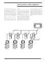
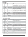
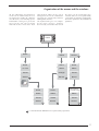
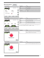
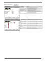
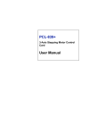
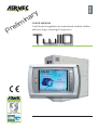
r
P
n
i
m
i
l
e
ISO 9001 - Cert. n° 0128/4
ENGLISH
y
r
a
USAGE MANUAL
Carel electrical regulation for water-based modular chillers
with two-stage centrifugal compressor
Tw110
TABLE OF CONTENTS
Characteristics of the electronic regulation
User interface
Function keys
3
4
5
Virtual keys (TOUCH-SCREEN)
5
Parameters visualised in the default mask
6
Organisation of the menus and the windows
7
USER menu parameters
8
CLOCK menu parameters
9
STATUS menu parameters
10
IN/OUT menu parameters
11
COMPRESSOR menu parameters
12
LOG menu parameters
14
Alarm management
15
Alarm codes
16
Characteristics of the regulation
hierarchy; in this mode, each card will
be connected to loads, transducers and
alarms relating to the compressor it
controls, but only the master card will
control the main functions of the unit.
For further information relating to the
network connection for more than one
unit, refer to the specific section of this
manual.
network
In the first case, the electronic
regulation of the unit will consist of an
electric control card PCO1, connected
to a touchscreen colour display, via
which the user can monitor/modify the
working of the unit.
If more than one unit is installed, and
these are connected to each other, the
system will be managed according
to the logic expressed in the diagram
below. The display to pilot the units
will be connected to the PCO1 cards
of the machines, and these will be
organised on the basis of a master/slave
The regulation of the unit TW110 is
made by using a PCO1 card (one for
each compressor of the system) and a
touchscreen display for each unit.
The use of the unit TW110 offers
t wo d i f f e r e n t p l a n t e n g i n e e r i n g
solutions, each producing distinctive
characteristics in the management of the
machine. The possible configurations
are:
• a single unit TW110 installed in the
system
• more than one unit (maximum
four) installed in a single system,
and connected to each other via the
Prg
Esc
PLAN
Slave 3
Slave 2
Slave 1
Master
Fuse
Fuse
Fuse
Fuse
MODBUS
Programming Key
Programming Key
Programming Key
Programming Key
PCO1
chiller
interface
unità 4
PCO1
chiller
interface
unità 3
PCO1
PCO1
chiller
interface
chiller
interface
unità 2
unità 1
BMS
3
User interface
The user interface consists of a
touchscreen colour graphic display; all
the functions of the unit are visualised
and modified via this interface.
The user utilises the display by means
of two types of command - the first via
the keys on the right-hand side (figure
below), and the second via the graphic
keys visualised in the various screens
(that can be used by pressing directly
on the screen, thanks to the touchscreen
function).
Function keys
A
B
C
D
E
Prg
Esc
F
Prg
Esc
G
Virtual keys (touchscreen)
A
Home
d
j
B
C
Status
D
In / Out
E
Utente
F
Orologio
G
Service
H
Storico
I
Prg
Esc
L
Back
4
M
Function keys
KEY
D
E
Function
ON / OFF
ALARM
USE
Notes
Switches the unit on/off
This command is always given priority with regard to the remote or supervisor
command. If the system is multicompressor, by pressing this key on the MASTER
unit you switch the entire system on or off; if you press it on a SLAVE unit, you
switch the single circuit on or off.
Visualises/resets the alarms
Pressed once, it visualises the alarms activated and switches off the alarm buzzer.
In alarm visualisation mode, if you press the key a second time you reset the
alarm(s) currently indicated; if no alarm has been generated, the pressing of this
key will produce the message NO ALARM ACTIVATED. The sequence of the alarms
is given by pressing the arrow keys UP and DOWN.
A-C
Arrow keys
Scroll through data UP/DOWN
These keys scroll through the masks of a menu; you can pass from the last to
the first, and vice versa. If the cursor is in a numerical field, the keys increase or
decrease the value on which the cursor is positioned. If the cursor is positioned
on a field of choice, by pressing the arrow keys UP/DOWN, you can visualise the
available options (e.g. YES/NO).
B
ENTER
Confirmation key
In the value setting masks, by pressing the key once, the cursor moves onto the
first introduction field; by pressing again, you confirm the value set and move the
cursor onto the next field. From the last field, the cursor is then hidden.
F
PRG
Activates FACTORY menu
Pressing this key, you access the FACTORY menu (after inserting the password)
that allows you to visualise the parameter settings of the manufacturer.
Changes control card
If the system is multicompressor, the display visualises the parameters and
information of one electric control card (PCO1) at a time; by pressing this key, the
display visualises the data from the next card (with the following increase logic:
MASTER, SLAVE1, SLAVE2, SLAVE3, SLAVE4).
G
ESC
Virtual keys (touchscreen)
KEY
Function
USE
A
Compressor
Activates compressor menu
status
On the STATUS mask, there is the virtual key (with a picture of the compressor);
when pressed, you access the compressor menu.
B
Home
By pressing this key, the visualisation returns to the main mask, where the water
inlet and outlet temperatures are shown, plus the machine status, the time
and day of the week, which PCO1 card is being controlled, and other specific
information.
C
Operating mode Type of operation
This key allows you to set the COLD/HOT operation.
D
STATUS
Activates the STATUS menu
Selects the STATUS mask in which there is a summary of the main working
parameters of the unit, with clear graphic representations and access to the
IN/OUT menu.
E
IN/OUT
Activates the IN/OUT menu
Selects the INPUT/OUTPUT menu to visualise analogical inputs and outputs,
and the status of the digital inputs and outputs of the PCO1 electric control card
selected.
F
User
Activates the USER menu
Selects the USER menu, with the settings of the user setpoint and access to the
clock menu.
G
Clock
Activates the CLOCK menu
Selects the CLOCK menu and time band programming.
H
SERVICE
Activates the SERVICE menu
By pressing this key, you access the SERVICE menu (after inserting the password)
that contains the settings of the maintenance parameters, and you can also
access the ALARM LOG menu.
I
LOG
Activates the ALARM LOG menu
This key allows you to access the ALARM LOG menu, where the recent anomalies
are stored.
L
ARROWS
UP, DOWN, ENTER
These keys have the same function as the function keys A-C, B (arrow UP, arrow
DOWN, ENTER key).
M
BACK
BACK
This key allows you to return to the visualisation of the previous menu.
Returns to the main menu
Notes
5
Parameters visualised in the default mask
Once the unit has been started up, a
default mask is visualised, showing
some fundamental parameters. These
parameters allow the user a quick
overall view of the working of the unit,
or units (in the case of multicompressor
systems). The parameters visualised
during this initial phase are:
A
B
C
D
16:32 VEN 20 / 01 /06
ON
U: 00
E
d
Ingresso acqua EV. +00.0 °C
F
Uscita acqua EV.
G
+00.0 °C
H
R.P.M.
I
Prg
L
ver. Hercules 1.0
d
j
Staus
Utente
Service
Esc
Parameter Function
Notes
A
TIME
Time set for the system.
B
DAY
Day set for the system.
C
DATE
Date set for the system.
D
PCO1 address
Indicates on which PCO1 card you are working (only for the multicompressors).
E
Working mode
Indicates the working mode selected.
F
Working status of the unit
ON = machine switched on
OFF BY KEYB = machine switched off via keyboard command
OFF BY DIG IN = machine switched off via remote contact
OFF BY SUPERV = machine switched off by supervisor
OFF BY TIME Z = machine switched off via timer
OFF BY ALARM = machine switched off by alarm
G
WATER INLET temperature
Indicates the EVAPORATOR WATER INLET temperature (CONDENSER in the case of water-water
unit, hot working mode).
H
WATER OUTLET temperature
Indicates the EVAPORATOR WATER OUTLET temperature (CONDENSER in the case of waterwater unit, hot working mode).
I
Compressor r.p.m.
Indicates the number of rotations per minute of the centrifugal compressor.
L
Software version
Indicates the version of the software installed on the PCO1 electric control card selected.
6
Organisation of the menus and the windows
All the information and parameters
visualised or modified by the user
are organised according to a different
series of menus, each including specific
information relating to a particular
aspect of the unit. The hierarchy
with which these menus have been
implemented allows for the quick
management of all the information
regarding the moment-by-moment
working of the machine.
The layout below gives an example
of the menu structure, showing
the hierarchy (remember that not all
the menus can be activated by mere
selection: some are, in fact, protected by
a password, to avoid the manipulation
of sensitive parameters by unauthorised
personnel).
Home
Prg
Esc
Status
Utente
Service
Home
Home
Home
In / Out
Status
Status
Utente
Orologio
Utente
Service
Storico
Service
*
*
*
solo se manca
la scheda orologio
Home
Home
Status
Status
Status
Utente
Utente
Utente
Service
Service
Service
*
*
*
*
= remember that the SERVICE menu is protected by a password
7
Menu parameters
Utente
Display visualisation
USER
Pag 1
Setpoint acqua
d
d
j
j
07.0 °C
11.0 °C
50.0 °C
45.0 °C
Setpoint
Secondo Setpoint
Setpoint
Secondo Setpoint
Setpoint recupero di calore
Setpoint recuperatore
Diff. recuperatore
Home
50.0 °C
05.0 °C
Staus
Orologio
Parameters
Notes
Setpoint
Setting of cold setpoint
Second Setpoint
Setting of second cold setpoint (only if the double setpoint
function of the SERVICE menu is activated)
Setpoint
Setting of hot setpoint
Second Setpoint
Setting of second hot setpoint (only if the double setpoint
function of the SERVICE menu is activated)
Recuperator Setpoint
Setting of setpoint to start the proportional band for the
recovery thermostat
Recuperator differential
Differential for the proportional band of the recovery
thermostat
Parameters
Notes
Setpoint used
Setpoint currently used, selected from those possible
(hot, cold, double hot, double cold, multifunction input,
serial)
Serial Limit
Limit of the power, owing to serial or multifunction input
request
Serial Demand
Power request from serial (visible only if the multichiller
function is enabled). The green traffic light symbol
indicates that the communication is active, and the %
figure of requested power is valid; red indicates that the
communication is not present, so the machine remains
idle, waiting for a reliable figure
Parameters
Notes
Multifunction input
Status of multifunction entry from digital input ID14
Service
Display visualisation
USER Pag 2
Comandi attuali
Setpoint utilizzato
07.0 °C
Comandi da seriale
Serial limit
100 %
Serial Demand
000 %
Home
Staus
Orologio
Service
Display visualisation
USER Pag 3
Ingresso multifunzione
Ingresso
d Setpoint
j Setpoint
Limit
Demand
d Compensation
j Compensation
Home
8
Staus
OFF
+000.0 °C
+00.0 °C
+00.0 °C
000 %
000 %
+00.0 °C
+00.0 °C
Orologio
Service
Inlet
Input value in the size selected
Setpoint
Cold setpoint from multifunction input
Setpoint
Hot setpoint from multifunction input
Limit
Limit of maximum power from multifunction input
Demand
Power requested from multifunction input
Compensation
Compensation of cold set from multifunction input
Compensation
Compensation of hot set from multifunction input
Menu parameters
Orologio
Display visualisation
OROLOGIO
ORA
DATA
GIORNO
16:43
20/01/06
Venerdì
FASCE ORARIE
OFF
Home
Staus
Utente
Pag 1
OROLOGIO
Pag 2
Giorno Non inizializzato
STOP1
00:00
START2
00:00
ON
Home
STOP2
00:00
Utente
Time of the system
DATE
Date of the system
DAY
Day of the week
Time bands
Enablement of the working with time bands for switching
on and off
Parameters
Notes
DAY
Day of the week in which to set the time bands
START1
Switch-on time for the chiller
STOP1
Switch-off time for the chiller
START2
Second switch-on time for the chiller
STOP2
Second switch-off time for the chiller
N.B: the wording TIMER ERROR may appear if the start and stop times are
not coherent (START1<=STOP1<=START2<=STOP2)
ON
Staus
Notes
TIME
Service
Display visualisation
START1
00:00
Parameters
Service
Display visualisation
Parameters
Notes
This screen appears if the clock card is not installed (or is
faulty) on the PCO1 electric control card; the clock card
should be installed in the “Clock Card” slot
STOP
SCHEDA OROLOGIO
NON INSTALLATA
Back
Display visualisation
Parameters
Notes
This screen appears only if you try to access the clock
menu from a slave card (PLAN address different from 1)
STOP
ACCESSO SOLO DA
SCHEDA MASTER
Back
9
Menu parameters
Status
Display visualisation
AP
00.0 bar
Tman +000.0 °C
Tco
+00 °C
Subc.
000 °C
Home
10
In / Out
Notes
AP
High pressure (in delivery)
TUAH +00.0 °C
Tman
Compressor delivery temperature
TIAH +00.0 °C
Tco
Condensing temperature
Subc.
Under-cooling
RPM 0000.0
KW in 000.0 KW
Amp
000 A
BP
00.0 bar
Tasp
+00.0 °C
Tev
+00 °C
Superh +00 °C
Parameters
TIA
+00.0 °C
TUA +00.0 °C
Utente
Service
BP
Low pressure (suction)
Tasp
Compressor suction temperature
Tev
Evaporation temperature
Superh
Overheating
RPM
Rotations per minute of the compressor
KW in
Input power to the compressor
Amp
Input current to the compressor
TUAH
Water outlet temperature from condenser
TIAH
Water inlet temperature from condenser
TIA
Water inlet temperature in evaporator
TUA
Water outlet temperature from evaporator
Menu parameters
In / Out
Display visualisation
Richiesta potenza
Power demand
Home
Staus
Utente
Carichi
Home
OFF
RA
Power requested by thermostat, in kW
Power requested by thermostat, in %
Proportional error of the thermostat
Integral error
Integral error of the thermostat
Safety limit
Limit of maximum power activated, limits the request of
the thermostat to the value shown
Parameters
Notes
MPOE
Status of evaporator pump relay output
RS
Status of evaporator antifreeze resistance relay output
MV/MPOC
Status of condenser pump relay output
VSL
Status of liquid solenoid valve relay output
Service
Display visualisation
MPOE
RS
MV/MPOC
VSL
VECO
VSBS
Interlock
Notes
Power demand
Proportional error
000.0 °C
000.0 %
+000 %
+000 %
000 %
Err. Proporzionale
Err. Integrale
Lim safety
Parameters
OFF
OFF
OFF
OFF
VECO
Status of economiser valve relay output
VSBS
Status of bypass start valve relay output
Interlock
Status of interlock contact relay output for compresssor
(contact open = compressor stop)
RA
Status of alarm summary relay output
OFF
OFF
OFF
Staus
Utente
Service
11
Menu parameters
Display visualisation
COMPRESSORE-DATI
Rpm attuali
Rpm richiesti
Rpm max
Rpm min
Cavity Temp.
Inverter Temp.
SCR Temp.
AP Turbo
Home
00000
00000
00000
00000
+000.0 °C
+000.0 °C
+000.0 °C
00.0 bar
Staus
3ph Vac 000 V
3ph Amp 000 A
Motor Pow 000.0 KW
IGV
000.0 %
Solenoide 1
Solenoide 2
OFF
Utente
Service
COMPRESSORE-STATO
ERRORE
Lockedout
OFF
MaxFlow
OFF
Resetting
OFF
MinIgv
OFF
Rampingup
OFF
InterlockOpen
OFF
HalfCloseVane
OFF
Faultwaiting
OFF
NormalState
OFF
Temperaturestop
OFF
Loadingup
OFF
Staus
Utente
Notes
Current rpm
Current rotations/minute of the compressor
Rpm requested
Rotations/minute requested by the thermostat
Maximum rpm
Maximum rotations/min possible, under current working
conditions
Minimum rpm
Minimum rotations/min possible, under current working
conditions
Cavity temperature
Winding temperature compressor motor
Inverter temperature
Temperature of compressor inverter
OFF
Display visualisation
Home
Parameters
Service
SCR temperature
Temperature of rectifier diodes
AP Turbo
Compressor condensation pressure (upstream from the
single-direction delivery valve)
3ph Vac
Three-phase voltage at compressor input
3ph Amp
Input current to the compressor
Motor Power
Electrical input power to compressor
IGV
Percentage (0~110%) of IGV valve opening
Solenoid 1
Status of cooling solenoid for compressor inverter (1
stage)
Solenoid 2
Status of second cooling solenoid for compressor inverter
(2-stage)
Parameters
Notes
ERROR: error in the selection of the command mode
CALIBRATION MODE: in internal calibration
Compressor command MANUAL MODE: control via monitoring program
modes
ANALOG MODE: control via 0-10V
MODBUS MODE: control via modbus
CHILLER MODE: control via probes
Lockedout
The compressor is in a serious alarm condition; it is
necessary to disconnect and reconnect the voltage to
unblock it. WARNING: do not carry out this operation
without checking the reason for the serious block
Resetting
The compressor is in the initialisation phase, following a
firing
Rampingup
The compressor is carrying out the initial rotation
increase phase in start-up
HalfCloseVana
The IGV valve is 50% open
NormalState
The compressor is in a normal condition
Loadingup
The compressor is in the rotation increase phase
MaxFlow
The IGV valve is completely open
MinIgv
InterlockOpen
Faultwaiting
Temperaturestop
12
Display visualisation
COMPRESSORE-Preallarmi
Invertertemp
Dischargetemp
Suctionpres
Dischargepres
Phasecurrent
Cavitytemp
Leavingwater
Home
OFF
OFF
OFF
OFF
OFF
OFF
CP ratio
SCRtemp
Preal. Bearing
00000
OFF
OFF
Preal. Motor
00000
OFF
Staus
Utente
Service
Parameters
Notes
Invertertemp
Pre-alarm excess temperature inverter
Dischargetemp
Pre-alarm excess temperature delivery
Suctionpres
Pre-alarm low pressure
Dischargepres
Pre-alarm high pressure
Phasecurrent
Pre-alarm excessive current absorption
Cavitytemp
Pre-alarm excess temperature motor winding
Leavingwater
Pre-alarm antifreeze
CP ratio
Pre-alarm compression ratio
SCRtemp
Pre-alarm excessively high temperature SCR diodes
Preal. Bearing
Pre-alarm code magnetic bearings
Preal. Motor
Pre-alarm code compressor motor
13
Menu parameters
Storico
Display visualisation
Parameters
Notes
Alarm Log
The alarm log allows you to view the last 100 alarms
activated. For each alarm, a series of parameters is
stored, with the values present at the time of the alarm.
The alarm log cannot be reset, and the storage is circular,
so each new alarm registered overwrites the oldest of
the 100 stored
STORICO ALLARMI Pag 1
N°
Nessun allarme
Volt
000
RPM
00000
TIA
+00.0 °C
TUA
+00.0 °C
AP
00.0 bar
BP
00.0 bar
000
00:00
Amp
IGV
TGP
Set
Diff.
Set AG
00/00/00
000
000.0 %
+000.0 °C
+00.0 °C
00.0 °C
+00.0 °C
Back
n°
Progressive number of the alarm (from 0 to 100)
No alarm
00:00 00/00/00
Code and description of the alarm, followed by time and
date when the alarm occurred
Volt
Three-phase voltage applied to the compresssor
RPM
Rotations per minute of the compresssor
TIA
Evaporator water inlet temperature
TUA
Evaporator water outlet temperature
AP
High pressure
BP
Low pressure
Amp
Input current to the compressor
IGV
Percentage of opening of the IGV capacity control valve
TGP
Force gas temperature
Set
Setpoint used in the production of evaporator outlet
water
Diff.
Differential used by the setpoint
SetAG
Antifreeze set
Load next alarm
Load previous alarm
Display visualisation
Parameters
Notes
This window appears if the alarm log is not available, due
to the absence of the clock card
STOP
STORICO NON DISPONIBILE
d
14
j
Staus
Utente
Service
Alarm management
The electric control card of the unit
TW110 monitors the moment-bymoment working of the machine, and
if an irregular situation arises, an alarm
is activated. The alarms are visualised
at different levels; the first signal
is indicated by a LED located on the
left-hand side of the display. This LED,
usually switched off, switches on when
an alarm condition arises. To pass to
the visualisation of the code and the
relative description, it is necessary to
press the alarm key (identified by the
bell; ref. page 5) positioned on the lefthand side of the display. At this point,
a window will appear on the screen,
showing the code and description of the
current alarm. There is also a virtual key
with which you can reset the error and
re-equip the unit.
Remember that, before resetting the
alarm, it is necessary to resolve the
cause of the error. Bear in mind also
that every alarm blocks the working of
the unit, which cannot restart until the
error has been reset.
Prg
Esc
A
B
CODICE ALLARME
DESCRIZIONE ALLARME
C
RESET
Prg
Home
Staus
Utente
Service
D
Esc
Parameters
Function
A
Alarm code
B
Alarm description
C
Virtual key to reset the error and re-equip the unit
D
Navigation keys
15
Alarm codes
Code
Description
001
Automatic re-equip alarm
002
Voltage or phase monitoring alarm
003
Antifreeze alarm
004
Compressor thermal alarm
005
Flow switch alarm
006
Pressure differential alarm
007
Pressure switch alarm (high pressure)
008
Transducer alarm (high pressure)
009
Pressure switch alarm (low pressure)
010
Transducer alarm (low pressure)
011
Force gas high temperature alarm
012
Fan heating alarm
013
Condenser pump heating alarm
014
Evaporator pump heating alarm
015
Evaporator pump maintenance alarm
016
Condenser pump maintenance alarm
017
Compressor maintenance alarm
018
Probe alarm: probe B1 faulty or not connected
019
Probe alarm: probe B2 faulty or not connected
020
Probe alarm: probe B3 faulty or not connected
021
Probe alarm: probe B4 faulty or not connected
022
Probe alarm: probe B5 faulty or not connected
023
Probe alarm: probe B6 faulty or not connected
024
Probe alarm: probe B7 faulty or not connected
025
Probe alarm: probe B8 faulty or not connected
026
Condenser water filter alarm
027
Alarm: low pressure
028
Alarm: unit 1 not connected
029
Alarm: unit 2 not connected
030
Alarm: unit 3 not connected
031
Alarm: unit 4 not connected
032
Compressor inverter temperature alarm
033
Delivery temperature alarm
034
Compressor suction pressure alarm
035
Compressor delivery pressure alarm
036
Power supply current alarm
037
Compressor internal temperature alarm
038
Alarm: TURBOCOR LEAVING WATER
039
Alarm: TURBOCOR COMPRESSOR RATIO
040
BEARING MOTOR alarm
041
Alarm: TURBOCOR SCR TEMPERATURE
042
SYSTEM LOCK OUT alarm
043
Alarm: CALIBRATION FAILED
044
Alarm: START CHECK FAILED
045
Alarm: TURBOCOR AXIAL DISPLACEMENT
046
Alarm: TURBOCOR AXIAL STATIC LOAD
047
Alarm: TURBOCOR FRONT RADIAL DISPLACEMENT X
16
Code
Description
048
Alarm: TURBOCOR FRONT RADIAL DISPLACEMENT Y
049
Alarm: TURBOCOR FRONT RADIAL STATIC LOAD X
050
Alarm: TURBOCOR FRONT RADIAL STATIC LOAD Y
051
Alarm: TURBOCOR BACK RADIAL DISPLACEMENT X
052
Alarm: TURBOCOR BACK RADIAL DISPLACEMENT Y
053
Alarm: TURBOCOR BACK RADIAL STATIC LOAD
054
Alarm: TURBOCOR BACK RADIAL STATIC LOAD Y
055
Alarm: TURBOCOR SINGLE PHASE OVERCURRENT
056
Alarm: TURBOCOR DC BUS HIGH VOLTAGE
057
Alarm: TURBOCOR HIGH CURRENT MOTOR (LW)
058
Alarm: TURBOCOR HIGH CURRENT MOTOR (LE)
059
Alarm: TURBOCOR IGBT INVERTER ERROR SIGNAL
060
Alarm: TURBOCOR HIGH CURRENT START-UP
061
Alarm: TURBOCOR BEARING ERROR
062
Alarm: TURBOCOR BEARING WARNING
063
Alarm: TURBOCOR OUTPUT VOLTAGE ON THE MOTOR GENERATES NO CURRENT
064
Alarm: TURBOCOR AVC DATA MISSING
065
Alarm: TURBOCOR MOTOR BACK EMF LOW
066
Alarm: TURBOCOR EEPROM CHECKSUM ERROR
067
Alarm: TURBOCOR COMPRESSOR IS RUNNING IN GENERATOR MODE
068
Alarm: TURBOCOR SCR PHASE LOSS
069
Alarm: communication error
070
Alarm: waiting for reduction differential pressures
17
18
19