1
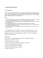
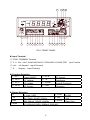
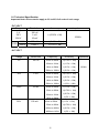
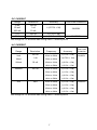
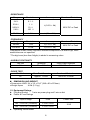
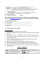
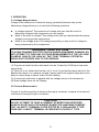
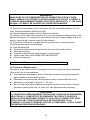
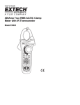
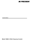
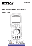
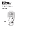
Instruction Manual
Model 2831D
4 ½ Digit True RMS Digital Multimeter
CONTENTS
1. PRODUCT DESCRIPTION
1-1. Introduction ---------------------------------------------------------
(3)
1-2. Technical Specifications ----------------------------------------
(6)
1-3. Equipment Ratings -----------------------------------------------
(8)
1-4. Supplied Accessories --------------------------------------------
(9)
1-5. International electrical Symbol --------------------------------
(9)
2. INSTALLATION
2-1. Initial Inspection ---------------------------------------------------
(10)
2-2. Connecting AC Power -------------------------------------------
(10)
2-3. Cooling and Ventilation -----------------------------------------
(10)
2-4. Position --------------------------------------------------------------
(10)
2-5. Warming-Up -------------------------------------------------------
(10)
3. OPERATION
3-1 Voltage Measurement --------------------------------------------
(11)
3-2 Current Measurement --------------------------------------------
(11)
3-3 Resistance Measurement ---------------------------------------
(12)
3-4 Diode Measurement ----------------------------------------------
(13)
3-5 Continuity Test -----------------------------------------------------
(13)
3-6 Frequency Measurement ---------------------------------------
(13)
4. MAINTENANCE
4-1. Fuse Replacement -----------------------------------------------
(14)
4-2. Adjustment and Calibration ------------------------------------
(14)
4-3. Cleaning and decontamination -------------------------------
(14)
2
1. PRODUCT DESCRIPTION
1-1. Introduction
Thank you for purchasing our product. Electronic measuring instruments produced
by us are high technology products made under strict quality control. We guarantee
their exceptional precision and utmost reliability. For proper use of the product,
please read this operation manual carefully.
Note
1. To fully maintain the precision and reliability of the product use it within the range
of standard setting (Temperature 10 °C~35 °C, Humidity 45%~85%)
2. After turning of power, please allow a pre-heating period of as long as some 30
minutes before use.
3. This equipment should be used with a triple line power cord for safety.
4. For quality improvement the exterior design and specification of the product can
be changed without prior notice.
5. If you have further questions concerning use, please contact our service center
or sales outlet.
This Digital multimeter is a portable, bench type Digital multimeter with a 4 1/2
digit light-emitting diode. This Digital multimeter can make diode measurements,
Frequency measurements & continuity test, in addition to Current, Voltage and
Resistance measurements.
Features
• Bench type True RMS Digital Multimeter with 4 1/2 digit (LED)display.
• Basic accuracy for DCV ; 0.05 %
• Overload protection on all range
• AC/DC Voltage measurement(Up to DC 1200V, AC 750V)
• AC/DC Current measurement(Up to 20A)
• Resistance measurement(Up to 20M Ω)
• Frequency Measurement(Up to 200KHz)
• Audible continuity test
3
b
1
2 3 4 5 6 7 8
9
c d e
10 11 12 13 14
a
FIG.1 FRONT PANEL
Input Terminal
ⓑ COM : COMMON Terminal
ⓒ V /Ω /Hz : VOLT/ OHM/CONTINUITY/ FREQUENCY/ DIODE TEST Input Terminal
ⓓ mA :
mil Ampere
ⓔ A
Ampere
:
Input Terminal
Input Terminal
Function Selection
① I/O
Power ON/OFF
⑤ AC A
AC Current
② DC V
DC Voltage
Resistance
③ AC V
AC Voltage
⑥ Ω
⑦ DIODE
Diode & Continuity
④ DC A
DC Current
⑧ FRQ
Frequency
Range Selection
⑨2
2V, 2mA ,2 KΩ
⑬ 20 M
20 MΩ
⑩20
20V, 20mA , 20 KΩ, 20 KHz
⑭ 20A
20A
⑪200
200V,200mA, 200KΩ, 200KHz
ⓐ HOLD
Data Hold
⑫2000
DC 1200V/AC1000V, 2000mA, 2000 KΩ
4
Input Terminal Limits
Input
Switch
Terminals
Function
Red
Black
DC V
AC V
OHM
Diode/Cont.
DC mA
AC mA
DC A
AC A
Frequency
VΩHz
VΩHz
VΩHz
VΩHz
mA
mA
A
A
VΩHz
COM
COM
COM
COM
COM
COM
COM
COM
COM
Min. Display
Reading
Max. Display
Reading
0.0001V
0.0001V
0.0001KΩ
0.1
0.0001mA
0.0001mA
0.001 A
0.001 A
0.001KHz
1200.0V
1000.0V
19.999MΩ
1999.9
1999.9mA
1999.9mA
19.999 A
19.999 A
199.99KHz
VOLTAGE
115V ~
230V ~
Maximum
Input
1200Vdc,
1000 Vac
600 V(1Min)
600 V(1Min)
2A
2A
20.00 A
20.00 A
600 V(1 Min)
FUSE POWER MAX
0.5A F
10W
0.2A F
10W
S/N :
Made in Korea
FIG.2 REAR PANEL
AC INLET
: AC power input connector
VOLTAGE SELECTOR : Selects the AC Power (115V or 230V)
FUSE HOLDER
: Replace fuse by unscrewing.
GROUND TERMINAL
5
1-2 Technical Specification
Important Note: All accuracies apply to 5% to 95% full scale of each range
- DC VOLT
Range
Resolution
Accuracy
2V
20 V
200 V
100 uV
1 mV
10 mV
±(0.05% + 5d)
1000V
100m V
±(0.1% + 5d)
1200V
100m V
±(0.3% + 5d)
Range
Resolution
Frequency
Accuracy
2V
100 uV
40Hz to 60Hz
±(0.75% + 10d)
60Hz to 1KHz
±(1.5% + 10d)
1KHz to 5KHz
±(2.5% + 10d)
5KHz to 10KHz
±(5.0% + 10d)
40Hz to 60Hz
±(0.75% + 10d)
60Hz to 1KHz
±(2.5% + 10d)
1KHz to 5KHz
±(5.0% + 10d)
5KHz to 10KHz
±(10% + 10d)
40Hz to 50Hz
±(1.0% + 10d)
50Hz to 60Hz
±(0.75% + 10d)
60Hz to 1KHz
±(2.5% + 10d)
1KHz to 5KHz
±(5% + 10d)
1200V
Impedance
10 MΩ
- AC VOLT
20V
200V
750V
1 mV
10 mV
100 mV
40Hz to 50Hz
±(1.0% + 10d)
50Hz to 60Hz
±(0.75% + 10d)
60Hz to 400Hz
±(2.5% + 10d)
400Hz to 1KHz
±(5% + 10d)
6
Impedance
10 MΩ
- DC CURRENT
Range
Resolution
Accuracy
2 mA
20 mA
200 mA
100 nA
1 uA
10 uA
±(0.75% + 5d)
2A
100 uA
±(1.0% + 5d)
20 A
1 mA
±(1.0 % + 10d)
Over Load Protection
2A/250V
15A/250V
20A Range for 15 seconds max during each 15 minute period
- AC CURRENT
Over Load
Range
Frequency
Accuracy
Protection
2mA
Resolution
100 nA
40Hz to 50Hz
±(1.5% + 10d)
2A/250V
20mA
1 uA
50Hz to 60Hz
±(0.75% + 10d)
200mA
10 uA
60Hz to 1KHz
±(2.0% + 10d)
1KHz to 5KHz
±(3.0% + 10d)
40Hz to 50Hz
±(1.5% + 10d)
50Hz to 60Hz
±(1.0% + 10d)
60Hz to 1KHz
±(2.0% + 10d)
1KHz to 5KHz
±(3.0% + 10d)
40Hz to 50Hz
±(1.5% + 10d)
50Hz to 60Hz
±(1.0% + 10d)
60Hz to 1KHz
±(2.0% + 10d)
1KHz to 2KHz
±(3.0% + 10d)
2000mA
20A
100 uA
1mA
20A Range for 15 seconds max during each 15 minute period
7
15A/250V
- RESISTANCE
Range
Resolution
Accuracy
2 KΩ
20 KΩ
200 KΩ
2 MΩ
0.1 Ω
1 Ω
10 Ω
100 Ω
±(0.2% + 6d)
20 MΩ
1 KΩ
±(1% + 10d)
Range
Resolution
Accuracy
20 KHz
1 Hz
±(1.5% + 5d)
200 KHz
10 Hz
±(2.0% + 5d)
Over Load Protection
600V DC or Peak
- FREQUENCY
Over Load Protection
600V DC or Peak
Frequencies under 500Hz requires a minimum amplitude of at least 4Vpp, other
sensitivities are not specified.
* The digit error(less than 5digits) is added in measuring value.
- AUDIBLE CONTINUITY
Test Volt
Threshold
Over Load Protection
3V
Less Than 200 ohm
600V DC or Peak
Test Volt
Max. Test Current
Over Load Protection
2V
Approx. 1.0 mA
600V DC or Peak
- DIODE TEST
DIMENSION AND WEIGHT
• Dimensions HWD: 9.4 x 3.5 x 10.6” (240 x 90 x 270mm)
• Weight Aprox
: 4.6lb (2.1 kg.)
1-3. Equipment Ratings
Plug and Socket : 3 wire ac power plug and 3 wire outlet
Power & Fuse Ratings
Input Voltage
Fuse
103 ∼ 126V AC (50/60Hz)
F 0.5A / 250V
206 ∼ 252V AC (50/60Hz)
F 0.2A / 250V
Operating Environment:
8
Power Max.
10 W
Temperature : 0°C to + 40 °C (Accuracy Specified at 23 °C ± 5 °C)
Temperature Coefficient : 0.1x( Specified Accuracy) per°C
HUMIDITY: up to 85% RH (Relative Humidity) to 40°C without temperature
extremes causing condensation within the instrument.
Storage Environment:
TEMPERATURE: -20°C to +70°C HUMIDITY: below 85% RH
Insulation Category II: Portable equipment of local level.
Pollution Degree: 2
Protection to IEC 529:
Ordinary
Note: Specifications and information are subject to change without notice.
Please visit www.bkprecision.com for the most current product information.
1-4. Supplied Accessories
User’s Manual ----------------------------------------------------Test Leads---------------------------------------------------------Power cord---------------------------------------------------------Spare Fuse---------------------------------------------------------
1
1
1
1
1-5. International electrical symbol
SAFETY RULES
Remember: THINK SAFETY AND ACT SAFELY.
Read these operating instructions thoroughly and completely before operating
this meter.
Pay particular attention to WARNINGS used for conditions and actions that
pose hazard to the user and CAUTIONS used for conditions and actions that
may damage the meter.
Always to inspect this meter, test probes and accessories for any sign of
damage or abnormality before every use.
Never ground yourself and keep your body isolated from ground.
Never touch exposed wiring, connections or any live circuit conductors.
Disconnect the live test probe before disconnecting the common test probe.
Use caution when working above 60V DC or 25V AC rms. Such voltages pose
a shock hazard.
SAFETY SYMBOLS
DANGEROUS VOLTAGE
SEE EXPLANATION IN MANUAL
AC-ALTERNATING CURRENT
GROUND
DC-DIRECT CURRENT
FUSE
9
2. INSTALLATION
2-1. Initial Inspection
This instrument was carefully inspected both mechanically and electrically
before shipment. It should be physically free of damage. To confirm this, the
instrument should be inspected for physical damage which may have occurred in
transit. Also, verify that all supplied accessories have been included.
2-2. Connecting AC Power
This instrument requires 115V AC or 230V AC (50-60 Hz) power socket with
protective earth contact (PE-contact). If it is available only a power socket without
PE-contact (so a 2-conductor ac power) then a power socket with PE-contact must
be installed before or the appliance should be provided with a PE-screw-terminal
which is not soluble by hand and not soluble before 2-conductor power lines.
CAUTION
AC POWER OF THIS INSTRUMENT IS PRESET TO 115V IN FACTORY.
BEFORE POWERING ON THIS INSTRUMENT, CHECK AND MAKE SURE THE
VOLTAGE OF THE POWER SOURCE IS SAME WITH THE MARKING OF UNIT.
IN CASE OF AC230V, VOLTAGE SELECTOR (on rear panel) SHOULD BE
SELECTED TO 230V POSITION.
2-3. Cooling and Ventilation
No special cooling and ventilation is required. However, the instrument should
be operated where the ambient temperature is maintained.
2-4. Position
This instrument is built as a bench-type instrument with rubber feet and tilt stand
in place. The stand-up angle can be adjusted by changing the angle of the carrying
handle.
2-5. Warming-Up
Allow at least 30 minutes for the unit to warm up so that it can stabilize.
10
3. OPERATION
3-1 Voltage Measurement
Voltage is the difference of electrical energy (potential) between two points.
Measuring voltage allows you to verify the following questions.
Is voltage present? The presence of voltage tells you that the circuit is
delivering voltage to the component you are testing.
What is the level of voltage? The voltage level tells you that whether the proper
voltage is arriving at the components.
What is the voltage drop? The voltage drop tells you how much of voltage is
being consumed by the components.
WARNING---HIGH VOLTAGE
TO AVOID POSSIBLE ELECTRIC SHOCK AND/OR EQUIPMENT DAMAGE, DO
NOT ATTEMPT TO TAKE ANY VOLTAGE MEASUREMENTS IF THE VOLTAGE
IS ABOVE 1200V DC OR 1000V AC. THE "COM" TERMINAL POTENTIAL
SHOULD NOT EXCEED 500V TO THE GROUND.
(1) Plug the red and the black test leads into the VΩ and the COM input terminals
respectively.
(2) Verify dc or ac. Select the function (dc V or ac V) and set the range switch to the
desired volt range. For unknown voltage, always start from highest range and move
down to lower range to select scale for best reading.
(3) Connect the probe tips in parallel with the voltage source to be measured.
(4) Read voltage value on the Display.
3-2 Current Measurement
Current is the flow quantity of electrons through a conductor. Ampere is the amount
of electrons flowing through a conductor.
CAUTION
DO NOT ATTEMPT TO TAKE A CURRENT OF MORE THAN SPECIFIED.
ALWAYS START WITH THE HIGHEST RANGE FOR UNKNOWN CURRENT.
THE “mA INPUT” TERMINAL IS PROTECTED BY A 2000mA/250V F TYPE
FUSE AND “A INPUT” TERMINAL IS FUSED WITH 15A/250V T TYPE.
11
WARNING
MAKE SURE OF NO POWER BEFORE DISCONNECTING CIRCUIT. EVEN
SMALL AMOUNT OF CURRENT CAN BE DANGEROUS. DO NOT ATTEMPT A
CURRENT MEASUREMENT WHERE VOLTAGE IS ABOVE 600 V. IF THE FUSE
BLOWS, YOU MIGHT BE INJURED OR THE METER DAMAGED.
(1) Plug the red test leads into the “mA input” for less than 2000 mA/dc or into “A
input” terminal between 2000mA and 20A.
(2) Plug the black test leads into the COM input terminal.
(3) Verify dc or ac. Select the function (dc A or ac A) and set the range switch to the
desired volt range. For unknown current, always start from highest range and move
down to lower range to select scale for best reading.
(4) Connect the probe tips in series with the current source to be measured.
(5) Read current value on the Display.
(6) Fuse Replacement
Disconnect and remove all connections from any live power source.
Open the top case.
Locate the defective fuse and remove it in input board.
Install a new fuse of the SAME SIZE AND RATING.
Close the top case.
**
20 A ac/dc Measurement - “Max . 15sec each 15minute”
3-3 Resistance Measurement
Resistance is an obstacle that is hindering the current flowing through a conductor.
Ohm is the unit of this resistance.
The resistance displayed in meter is the total resistance through all possible
paths between red and black probes.
Resistance must always be measured with meter in series with the circuit.
Resistance in test lead is about 0.1 - 0.2 ohm
Be sure that the contact between the probes and the circuit is clean. Contact
resistance coming from dirt, oil, paint, etc. can affect accuracy seriously.
CAUTION
ALL RESISTANCE MEASUREMENTS SHOULD BE TAKEN ON DE-ENERGIZED
CIRCUITS ONLY. COMPLETELY DE-ENERGIZE THE CIRCUIT OR DEVICE
WHICH IS TO BE MEASURED. POWER TO THE CIRCUIT UNDER TEST MUST
BE OFF AND ANY CAPACITORS SHOULD BE DISCHARGED. IF AN
EXTERNAL VOLTAGE IS PRESENT ACROSS A COMPONENT, IT WILL CAUSE
ERRONEOUS RESISTANCE READING.
12
(1) Plug the red and black test leads into the VΩ input and the COM input terminals
respectively.
(2) Select the function(OHM) and set the range switch to the desired resistance
range.
(3) Connect the probe tips in parallel with the resistance to be measured.
(4) Read resistance value on the Display.
3-4 Diode Measurement
A good diode allows current in one direction. To test a single diode, turn the
power off and remove the diode from circuit.
(1) Connect the red probe to the plus(+) side of diode and the black probe to the
minus(-) side.
(2) If diode is good, the voltage drop will be displayed. (ex : 300.0 ~ 800.0 )
(3) Reveres the probes and measure the voltage across the diode again.
If diode is good, the display shows “000.0” and is flickering.
If diode is shorted, the display shows 000.0 with beep sound in both direction.
If display shows “000.0” and is flickering in both directions, the diode is open.
3-5 Continuity test
Continuity test verifies by beeper if the circuit is closed or open.
Meter detects opens and shorts.
(1) Set the push switch to continuity function & diode range.
(2) Connect the probes to the circuit and listen for beeper. Continuity tone confirms
that the circuit is continued, closed and connected.
3-6 Frequency Measurement
(1) Plug the red and black test leads into the VΩ input and the COM input terminals
respectively.
(2) Select the function to FRQ. and set the range switch to the desired frequency
range. For unknown frequency, always start from highest range and move down to
lower range to select scale for best reading.
(3) Connect the probe tips in parallel with the circuit to be measured.
(4) Read frequency value on the Display.
NOTE ;
The digit error (less than 5digits) is added in measuring value.
To compensate this error, check the digit error by shorting test leads(+,-) before
measuring unknown frequency and deduct this value from measuring value.
13
4. MAINTENANCE
CAUTION
IT IS ESSENTIAL FOR SAFETY TO PROPERLY MAINTAIN AND SERVICE THIS
INSTRUMENT
WARNING
VOLTAGES WITHIN THIS INSTRUMENT ARE SUFFICIENTLY HIGH TO
ENDANGER LIFE. COVERS MUST NOT BE REMOVED EXCEPT BY PERSONS
QUALIFIED AND AUTHORIZED TO DO SO AND THESE PERSONS SHOULD
ALWAYS TAKE EXTREME CARE ONCE THE COVERS HAVE BEEN
REMOVED.
4-1. Fuse Replacement
Disconnect and remove all connections from any live power source.
Unscrew fuse holder by screw driver.
Locate the defective fuse and remove it by gently pulling-out.
Install a new fuse of the SAME SIZE AND RATING.
Screwing fuse holder.
CAUTION
MAKE SURE THAT THE RATED AND SPECIFIED FUSES ARE USED FOR
REPLACEMENT.
4-2. Adjustment And Calibration
It is recommendable to regularly adjust and calibrate this instrument. Qualified and
authorized personnel only should execute performance and procedures.
4-3. Cleaning and decontamination
The instrument can be cleaned with a soft clean cloth to remove any oil, grease or
grime. Never use liquid solvents or detergents. If the instrument gets wet for any
reason, dry the instrument using low-pressure clean air at less than 25 PSI. Use
care and caution around the window cover areas where water or air could enter into
the instrument while drying.
14
Limited One-Year Warranty
B&K Precision Corp. warrants to the original purchaser that its product and the
component parts thereof, will be free from defects in workmanship and materials for
a period of one year from the data of purchase.
B&K Precision Corp. will, without charge, repair or replace, at its’ option, defective
product or component parts.
Returned product must be accompanied by proof of
the purchase date in the form a sales receipt.
To obtain warranty coverage in the U.S.A., this product must be registered by
completing and mailing the enclosed warranty card to B&K Precision Corp., 22820
Savi Ranch Parkway, Yorba Linda, CA 92887 within fifteen (15) days from proof of
purchase.
Exclusions: This warranty does not apply in the event of misuse or abuse of the
product or as a result of unauthorized alternations or repairs.
It is void if the serial
number is alternated, defaced or removed.
B&K Precision Corp. shall not be liable for any consequential damages, including
without limitation damages resulting from loss of use.
Some states do not allow
limitation of incidental or consequential damages, so the above limitation or
exclusion may not apply to you.
This warranty gives you specific rights and you may have other rights, which vary
from state-to-state.
15
Model Number: ______________
Date Purchased:__________
Service Information
Warranty Service: Please return the product in the original packaging with proof of
purchase to the below address.
Clearly state in writing the performance problem
and return any leads, connectors and accessories that you are using with the
device.
Non-Warranty Service: Return the product in the original packaging to the below
address.
Clearly state in writing the performance problem and return any leads,
connectors and accessories that you are using with the device. Customers not on
open account must include payment in the form of a money order or credit card. For
the most current repair charges contact the factory before shipping the product.
Return all merchandise to B&K Precision Corp. with pre-paid shipping.
The flat-
rate repair charge includes return shipping to locations in North America.
For
overnight shipments and non-North America shipping fees contact B&K Precision
Corp..
B&K Precision Corp.
22820 Savi Ranch Parkway
Yorba Linda, CA
92887
Phone: 714- 921-9095
Facsimile: 714-921-6422
www.bkprecision.com
Include with the instrument your complete return shipping address, contact name,
phone number and description of problem.
16
22820 Savi Ranch Parkway
Yorba Linda, CA 92887
USA
TEL: 714-921-9095
FAX: 714-921-6422
www.bkprecision.com
PN: 481-532-9-001
Printed in Korea
©2004 B&K Precision Corp.
17