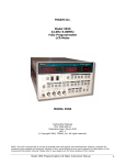
1
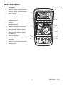
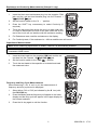
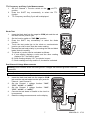
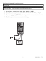
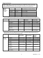
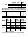
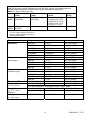
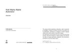
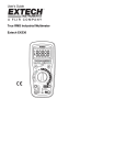
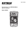
User Guide Dual Channel, True RMS MultiMeter with PC interface Model 380900 Introduction Congratulations on your purchase of the Extech 380900 Dual Channel, Datalogging, True RMS MultiMeter. This 60,000 count meter features dual input channels with dual display for measuring two voltages or voltage and current simultaneously. Additional measurements include Capacitance, Frequency, Resistance, Continuity, Duty Cycle and Diode test. Over 10,000 measurement readings on both channels can be logged by the meter and later transferred to PC using the RS-232 interface. Real-time meter/PC logging is also supported. This meter is shipped fully tested and calibrated and, with proper use, will provide years of reliable service. Safety International Safety Symbols This symbol, adjacent to another symbol or terminal, indicates the user must refer to the manual for further information. This symbol, adjacent to a terminal, indicates that, under normal use, hazardous voltages may be present Double Insulation or Reinforced insulation OVERVOLTAGE CATEGORY III This meter meets the IEC 610-1-95 standard for OVERVOLTAGE CATEGORY III. Cat III meters are protected against overvoltage transients in fixed installation at the distribution level. Examples include switches in the fixed installation and some equipment for industrial use with permanent connection to the fixed installation. 2 380900-EN v3.1 07/13 Safety Precautions 1. Improper use of this meter can cause damage, shock, injury or death. Read and understand this user’s manual before operating the meter. 2. Make sure any covers are properly closed and secured. 3. Always remove the test leads before replacing the battery or fuses. 4. Inspect the condition of the test leads and the meter itself for any damage before operating the meter. Repair or replace any damage before use. 5. Do not exceed the maximum rated input limits. 6. Use great care when making measurements if the voltages are greater than 25VAC rms or 35VDC. These voltages are considered a shock hazard. 7. Always discharge capacitors and remove power from the device under test before performing Capacitance, Diode, Resistance or Continuity tests. 8. Remove the battery from the meter if the meter is to be stored for long periods. 9. To avoid electric shock, do not measure AC current on any circuit whose voltage exceeds 1000V AC. 10. Voltage checks on electrical outlets can be difficult and misleading because of the uncertainty of connection to the electrical contacts. Other means should be used to ensure that the terminals are not "live". 11. The product is intended only for indoor use 12. If the equipment is used in a manner not specified by the manufacturer, the protection provided by the equipment may be impaired. 13. Pollution degree: 2 Input Limits Function Maximum Input V DC, V AC, Frequency, Duty Cycle 1000V DC/AC A AC, A DC 20A (30 seconds max) Resistance, Continuity 1000V DC/AC Capacitance 1000V DC/AC Diode test 1000V DC/AC 3 380900-EN v3.1 07/13 Meter Description 1. LCD display 2. Channel 2 value, unit and function 3. Channel 1 value, unit and function 4. ZERO function 5. Frequency function 3 6. Record function 7 7. Manual range key 8 8. Shift key 9. Max/Min/Hold key 10. Channel 1/Channel 2 select key 2 1 4 5 6 9 11 10 11. Rotary function selection switch for Channel 2 12 12. Rotary function selection switch for Channel 1 13. Common input jack 14. Channel 1 V/mV/Ω/Cap/Diode/TTL input jack 15 13 14 16 15. Channel 2 V/mV/mA/µA input jack 16. 10A input jack 4 380900-EN v3.1 07/13 Operation Measurement Considerations Notice: Read and understand all WARNING and CAUTION statements listed in the safety section of this operation manual prior to using this meter. 1. 2. 3. Always move the rotary function switch to the OFF position when the meter is not in use. If "OL" appears on the display during a measurement, the measurement exceeds the range selected. Change to a higher range. Functions used when the meter is in the dual channel mode may take longer to execute due to the fact that the meter is multiplexing. AC/DC Voltage Measurements 1. Insert the black test lead into the negative COM jack and the red test lead into the Channel 1 or Channel 2 input jack. 2. Set the function switch, for the selected channel, to the "VAC" "VDC" "mVAC" "mVDC" position. 3. 4. Connect the test leads to the circuit to be measured Read the voltage measurement on the display AC/DC Current Measurements (Channel 2 only) Note: When making single channel current measurements, set the Channel 1 rotary switch to the OFF position. CAUTION: Do not make 20A current measurements for longer than 30 seconds. Exceeding 30 seconds may cause damage to the meter and/or the test leads. 1. 2. 3. 4. 5. 6. 7. 8. Insert the black test lead into the negative COM jack. For current measurements up to 6000A, set the Channel 2 function switch to the "A" position and insert the red test lead into the Channel 2 mA-A jack. For current measurements up to 600mA, set the Channel 2 function switch to the "mA" position and insert the red test lead into the Channel 2 mA-A jack. For current measurements up to 10A, set the Channel 2 function switch to the "A" position and insert the red test lead into the A jack. Remove power from the circuit under test and open the circuit at the point where you wish to measure current. Touch the black test probe tip to the negative side of the circuit and touch the red test probe tip to the positive side of the circuit. Apply power to the circuit. Read the current on the display. 5 380900-EN v3.1 07/13 Resistance and Continuity Measurements (Channel 1 only) Note: When measuring resistance or continuity, Channel 2 is automatically disabled. 1. Insert the black test lead banana plug into the negative COM jack and the red test lead banana plug into the Channel 1 V//mV/CAP/ jack. 2. Set the function switch to the " 3. Press the SHIFT key momentarily to select Continuity (if required). 4. Touch the test probe tips across the circuit or part under test. It is best to disconnect one side of the part under test so the rest of the circuit will not interfere with the resistance reading. 5. For Resistance tests, read the resistance on the display. 6. For Continuity tests, if the resistance is < 40 an audible tone will sound " position. Capacitance Measurements Note: When measuring capacitance or diodes, Channel 2 is automatically disabled. Note: If auto range is selected, the range is 6000 counts. If manual range is selected, the range is extended to 9999 counts. 1. Insert the black lead into the negative COM jack and the red test lead into the Channel 1 V//mV/CAP/ jack. 2. 3. Set the function switch to the "CAP " position. Touch the test leads to the capacitor to be tested and read the measured value. Frequency and Duty Cycle Measurements When measuring V, mV, A, mA, or µA, the measurement of frequency and duty cycle can be displayed. 1. Select either CH1 or CH2 (as indicated by the ▼ icon) with the CH1/CH2 key. 2. Press the Hz key and the frequency will appear in the lower display and the duty cycle will appear in the upper display for the channel selected. 3. Press the Hz key again to exit the function. 6 380900-EN v3.1 07/13 TTL Frequency and Duty Cycle Measurements 1. Set the Channel 1 function switch to the mV/TTL position. 2. Press the SHIFT key momentarily to select the TTL function. 3. TTL Frequency and Duty Cycle will be displayed Diode Test 1. Insert the black lead into the negative COM jack and the red test lead into the positive jack. 2. Set the function switch to "CAP " position. 3. Press the SHIFT key momentarily to select the diode function. 4. Touch the test probe tips to the diode or semiconductor junction you wish to test. Note the meter reading. 5. Reverse the test lead polarity by reversing the red and black leads. Note this reading. 6. The diode or junction can be evaluated as follows: A. If one reading displays a value and the other reading displays "OL", the diode is good. B. If both readings display "OL", the device is open. C. If both readings are very small or 0, the device is shorted. Dual Channel Voltage Measurements Warning: Both channels share the same ground. Voltages with different grounds cannot be measured. Note: Functions may take longer to execute when in the dual channel mode. 1. 2. 3. 4. 5. Insert the black test lead into the negative COM jack and the red test leads into the input jacks for Channel 1 and Channel 2. Set the Channel 1 voltage function: "VAC", "VDC", "mVAC", or "mVDC". Set the Channel 2 voltage function: "VAC", "VDC", "mVAC", or "mVDC”. Connect the test leads in Parallel to the circuit to be measured. Read the voltage measurements on the display. 7 V1 V2 380900-EN v3.1 07/13 Dual Channel Voltage and Current Measurement Warning: Both channels share the same ground. Voltage and current with different grounds cannot be measured. Note: The COM jack should be used as the CURRENT ground. The A jack should be used as the VOLTAGE ground. The two grounds are connected internally by a fuse. 1. 2. 3. 4. 5. Set the Channel 1 voltage function: "VAC", "VDC", "mVAC", or "mVDC". Set the Channel 2 current function: "ACA", "DCA", "ACmA", "DCmA”, “ACµA”, or “DCµA”. Insert the test leads into the input jacks. Connect the test leads in PARALLEL to the voltage circuit to be measured, and connect the test leads in SERIES with the current to be measured. Read the voltage and current measurements on the display. 8 380900-EN v3.1 07/13 Advanced Functions MAX, MIN, Hold Function Note: The meter will exit autoranging and hold the present range when the MAX/MIN/H key is pressed. Pre-select a different range if required. This mode is used to “freeze” the display and also to enter the Max/Min recording mode. 1. Press and hold the MAX/MIN/H key until the meter beeps to freeze the LCD display. The 'H' (Hold) icon will appear on the display. 2. Press a second time and the “MAX” icon will appear with the maximum values recorded since the HOLD mode was entered. 3. Press a third time and the “MIN” icon will appear with the minimum values recorded since the HOLD mode was entered. 4. Pressing the key for a single beep will cycle the display through Hold, Maximum and Minimum. 5. Press and hold the key for two beeps to exit the mode. Relative Mode (ZERO) The Relative Mode permits the user to store the current measurement as a reference value and compare the reference value to subsequent readings. In Relative mode, the meter displays: Actual reading minus the Relative reference value. Press the "ZERO" key to enter the Relative mode. The triangular Relative icon and ZERO will appear on the display. The display will read zero indicating that the actual and relative measurements are the same. As the actual measurement changes, the display will indicate the difference between actual and reference (zeroed) value. Press and hold the ZERO key for two beeps to exit the Relative Mode. Range Hold Press the RANGE key to enter manual ranging for the channel selected by the ▼ icon. When selected, the meter will lock the present range. Press the RANGE key again to proceed to other ranges as indicated by the decimal point and units indicators. Press and hold the RANGE key for two beeps to return to the AUTO Ranging mode. 9 380900-EN v3.1 07/13 Datalogging The 380900 can store up to 10,708 records for both channels. These records can be transferred to a PC for storing, viewing and plotting using the RS-232 interface cable and Windows® software included. Data may also be stored directly into the PC using the software. Note: If a low battery condition is detected during datalogging, it will stop automatically. Note: Capacitance, frequency, duty cycle and logic functions cannot be recorded in the datalogging or data acquisition modes. Setting the Sampling Time 1. Hold the REC button and turn the power on. The top display will show the sampling rate in seconds. 2. To change the sampling time, press the RANGE button once to increment the sampling time by 1. The Sampling rate range is 0 to 253 seconds. Note: If the sampling time is set at 0 seconds, the DMM will record one measurement and stop. For dual channel datalogging, sampling time should be 2 seconds or greater. 3. To increment the sampling time faster, hold the RANGE button for more than 2 seconds. 4. When approaching the desired sampling time, release the RANGE button and then increment by 1 to reach the desired rate. 5. Hold the REC button for 2 seconds to return to the DMM function. Clearing Memory There are three methods to clear the memory. 1. Hold the REC button and turn the power on. The memory will clear and the top display will show the sampling rate in seconds. 2. Press the “Clear Data Logger Memory” button in the software datalogger screen. 3. Send a CNTL-C via the rs232 interface. Start and Stop Datalogging 1. Clear the memory before starting a datalogging session. 2. Press the REC button to start datalogging. The LCD will show an REC symbol. 3. To stop datalogging, press and hold the REC button until the REC symbol goes out. 4. To resume datalogging, press the REC button again. Note: If any function switches are changed from their original position at the start of datalogging, an ERR will be displayed and datalogging will not resume. Note: The Sample Rate should be set to 2 secs or greater for dual channel datalogging. Windows® Data Acquisition and Datalogging Software The supplied software is dedicated for use with the Extech Model 380900 Meter. The software displays data as a Data List or as an X-Y Graph. Data is stored as a text file that can then be opened in spreadsheet or other software programs Refer to the separate Software User Guide included on the supplied program CD-ROM for software specific instructions. 10 380900-EN v3.1 07/13 Specifications General Specifications Display Input Protection Two 5-digit displays on multi-function LCD with 30 segment bar graph Fast 20A/1000V fuse (10A input) Fast 1A/1000V fuse (mA/µA input) Datalogger memory 10,708 records for each channel Over range indication "OL" appears on the LCD Low battery indication Battery symbol appears on the LCD Power supply 9V Battery Battery life 100 hours (approx) Operating Temperature 14 to 104 F (-10 to 40 C) Operating Humidity less than 85% RH Storage Temperature -4 to 140 F (-20 to 60 C) o o o o Storage Humidity less than 75% RH Dimensions 8.15 x 4 x 1.85" (207 x 101 x 47mm) Weight Approx. 15.2 oz. (430g) with battery 11 380900-EN v3.1 07/13 Range Specifications IMPORTANT NOTE: The accuracy specifications for Voltage and Current in this section apply to single channel use. Refer to the supplemental dual channel specification at the end of this section for accuracy specs that apply to simultaneous dual channel use. DC Voltage (Input Impedance : 10MΩ) Range Resolution Accuracy for Channel 1 only (Note: add 0.02% for channel 2 accuracy) 60.000mV 600.00mV 6.0000V 60.000V 600.00V 1000.0V 0.001mV 0.01mV 0.0001V 0.001V 0.01V 0.1V ±(0.1%+5dgts) ±(0.03%+3dgts) ±(0.03%+3dgts) ±(0.03%+3dgts) ±(0.03%+3dgts) ±(0.04%+3dgts) For DC Voltage: Manually select the range to be tested, short the meter input and then ‘zero’ the reading by pressing the ZERO button (this applies to Channel 1 and Channel 2) before performing 60mV and 600mV tests. Function Range Resolution AC Voltage 60.000mV 600.00mV 6.0000V 60.000V 600.00V 1000.0V (0-400V) 1000. (400-1000V) 0.001mV 0.01mV 0.0001V 0.001V 0.01V 0.1V Accuracy (50/60Hz) ±(0.1%+20dgts) ±(0.1%+20dgts) ±(0.1%+20dgts) ±(0.1%+20dgts) ±(0.1%+20dgts) ±(0.1%+20dgts) Accuracy (45Hz-1KHz) ±(0.3%+20dgts) ±(0.3%+20dgts) ±(0.3%+20dgts) ±(0.3%+20dgts) ±(0.5%+20dgts) ±(2%+30dgts) 0.1V ±(0.1%+20dgts) (45Hz-400Hz) ±(2%+30dgts) For AC Voltage: Manually select the range to be tested, short the meter input and then ‘zero’ the reading by pressing the ZERO button (this applies to Channel 1 and Channel 2) before performing 60mV and 600mV tests. Accuracy note: The accuracy specifications for ACV shown in the table above apply to Channel 1 only. To calculate the Channel 2 accuracy, add an additional 0.05%. Function Range Accuracy (20Hz-45Hz) Accuracy (1KHz-10KHz) AC Voltage 60.000mV 600.00mV 6.0000V 60.000V 600.00V (0-400V) 600.00V (400-600V) 1000.0V (0-400V) 1000.0V (400-1000V) ±(0.8%+25dgts) ±(0.8%+25dgts) ±(0.8%+25dgts) ±(0.8%+25dgts) ±(0.8%+25dgts) ±(2%+20dgts) ±(1%+20dgts) ±(1%+20dgts) ±(1%+20dgts) ±(5%+20dgts) Accuracy (10KHz20KHz) ±(2.5%+20dgts) ±(2.5%+20dgts) ±(2.0%+20dgts) ±(2.0%+20dgts) Not Specified ±(0.8%+25dgts) Not Specified Not Specified ±(0.8%+25dgts) ±(2%+40dgts) Not Specified ±(0.8%+25dgts) Not Specified Not Specified (Continued) 12 380900-EN v3.1 07/13 Function Range Accuracy (20KHz-50KHz) AC Voltage 60.000mV 600.00mV 6.0000V 60.000V 600.00V 1000.0V ±(4%+40dgts) ±(2%+40dgts) ±(2%+40dgts) ±(4%+40dgts) (Continued) Accuracy (50KHz100KHz) ±(4%+40dgts) ±(2%+40dgts) ±(2%+40dgts) ±(4%+40dgts) Not Specified Not Specified Accuracy (100KHz200KHz) Not Specified ±(2%+40dgts) ±(2%+40dgts) Not Specified ACV Accuracy note: The accuracy specifications for ACV shown in the tables above apply to Channel 1 only. To calculate the Channel 2 accuracy, add an additional 0.05%. Other AC Voltage notes: The ACV or ACmV accuracy is specified for 6 to 100% of range from 20kHz to 200kHz, True rms, crest factor < 3 at full scale (< 6 at half scale except for the 1000V range where it is 1.5 at full scale and 3 at half scale). Input impedance is 10MW. Overload protection is 1000VAC. Function DC Current Range Resolution 600.00µA 0.01µA 6000.0µA 0.1µA 60.000mA 0.001mA 600.00mA 0.01mA 1.0000A 0.0001A 10.000A* 0.001A *20A for maximum 30 seconds Accuracy ±(0.2%+10dgts) ±(0.1%+10dgts) ±(0.2%+10dgts) ±(0.1%+10dgts) ±(0.1%+10dgts) ±(0.3%+10dgts) Notes for DC Current: The 10A terminal is protected by a 20A fast blow fuse. The uA and mA terminals are protected by a 1A fast blow fuse. Function AC Current Function AC Current (Continued) Range Resolution (ACA) 600.00µA 0.01µA 6000.0µA 0.1µA 60.000mA 0.001mA 600.00mA 0.01mA 1.0000A 0.0001A 10.000A* 0.001A * 20A for maximum 30 seconds Accuracy (50/60Hz) ±(0.3%+20dgts) ±(0.3%+20dgts) ±(0.3%+20dgts) ±(0.3%+20dgts) ±(0.3%+20dgts) ±(0.5%+20dgts) Accuracy (45Hz-1KHz) ±(0.4%+20dgts) ±(0.4%+20dgts) ±(0.4%+20dgts) ±(0.4%+20dgts) ±(0.4%+20dgts) ±(0.5%+20dgts) Range Accuracy (1KHz-10KHz) ±(2%+20dgts) ±(2%+20dgts) ±(0.5%+20dgts) ±(0.5%+20dgts) ±(1.5%+20dgts) ±(1.5%+20dgts) Accuracy (10KHz-20KHz) ±(1%+20dgts) ±(1%+20dgts) ±(1%+20dgts) ±(1%+20dgts) Not Specified Not Specified Accuracy (20Hz-45Hz) 600.00µA ±(1%+20dgts) 6000.0µA ±(1%+20dgts) 60.000mA ±(1%+20dgts) 600.00mA ±(1%+20dgts) 1.0000A ±(1%+20dgts) 10.000A* ±(2%+20dgts) * 20A for maximum 30 seconds Notes for AC Current: The accuracy is specified for 5 to 100% of range from 45Hz to 20KHz, True rms, 10A terminal is protected by a 20A fast blow fuse. The uA and mA terminals are protected by a 1A fast blow fuse. 13 380900-EN v3.1 07/13 Voltage and Current Supplemental Accuracy Specifications for Dual Channel use Add the accuracy figures listed below to the accuracy figures in the tables above for voltage and current when using the meter’s two channels simultaneously Note: For DC to 400Hz use only ACV DCV ACA DCA (CH2) (CH2) (CH2) (CH2) ACV ±1%±(V1-V2) ±0.5%±(V1-V2) * ±0.1µA/V (µA,CH2) ±0.25% (CH1) (200 PPM) (20 PPM) ±1µA/V (mA, CH2) ±0.2mA/V (A, CH2) ±2mV/A (mV, CH1) ±5mV/A (V, CH1) DCV ±0.5%±(V1-V2) * ±0.25% ±0.25% ±0.25% (CH1) 20 PPM Legend: V1: The voltage reading of Channel 1 V2: The voltage reading of Channel 2 PPM: parts per million Function Resistance Capacitance (auto range) Capacitance (manual range) Frequency (TTL) Frequency (AC sine wave) Duty Cycle (%, TTL, 1Hz to 600KHz) Duty Cycle (%, sine wave) Range 999.99Ω 9.9999KΩ Resolution 0.01Ω 0.0001KΩ Accuracy ±(0.19%+8dgts) ±(0.09%+3dgts) 99.999KΩ 0.001KΩ ±(0.09%+3dgts) 999.99KΩ 0.01KΩ ±(0.09%+3dgts) 9.9999MΩ 0.0001MΩ ±(0.2%+6dgts) 40.000MΩ 0.001MΩ ±(1%+6dgts) 60.00nF 0.01nF ±(0.8%+5dgts) 600.0nF 0.1nF ±(1.5%+5dgts) 6.000µF 0.001µF ±(1.5%+5dgts) 60.00µF 0.01µF ±(2.0%+5dgts) 490.0µF 0.1µF ±(3.5%+5dgts) 99.99nF 0.01nF ±(0.8%+5dgts) 999.9nF 0.1nF ±(1.5%+5dgts) 9.999µF 1µF ±(1.5%+5dgts) 99.99µF 0.01µF ±(2.0%+5dgts) 999.9µF 0.1µF ±(3.5%+5dgts) 1.000Hz-2MHz 0.01Hz-0.0001MHz ±(0.005%+4dgts) 1.000Hz-200KHz 0.01Hz-100Hz ±(0.02%+4dgts) Sine wave sensitivity: 100mV@mv range, 1V@V range 0.001%-9.999% 0.001% ±(30d/KHz+30dgts) 10.00%-100.00% 0.01% ±(3d/KHz+3dgts) 0.001%-100.00% 0.001%-0.01% 14 Not Specified 380900-EN v3.1 07/13 Maintenance WARNING: To avoid electric shock, disconnect the test leads from any source of voltage before removing the back cover or the battery or fuse covers. WARNING: To avoid electric shock, do not operate your meter until the battery and fuse covers are in place and fastened securely. This MultiMeter is designed to provide years of dependable service, if the following care instructions are performed: 1. KEEP THE METER DRY. If it gets wet, wipe it off. 2. USE AND STORE THE METER IN NORMAL TEMPERATURES. Temperature extremes can shorten the life of the electronic parts and distort or melt plastic parts. 3. HANDLE THE METER GENTLY AND CAREFULLY. Dropping it can damage the electronic parts or the case. 4. KEEP THE METER CLEAN. Wipe the case occasionally with a damp cloth. DO NOT use chemicals, cleaning solvents, or detergents. 5. USE ONLY FRESH BATTERIES OF THE RECOMMENDED SIZE AND TYPE. Remove old or weak batteries so they do not leak and damage the unit. 6. IF THE METER IS TO BE STORED FOR A LONG PERIOD OF TIME, the batteries should be removed to prevent damage to the unit. 15 380900-EN v3.1 07/13 Battery and Fuse Installation WARNING: To avoid electric shock, disconnect the test leads from any source of voltage before removing the battery cover. 1. Turn power off and disconnect the test leads from the meter. 2. Remove the protective rubber holster. 3. Open the rear battery and fuse cover by removing the screw using a Phillips head screwdriver. 4. Insert the battery into battery holder, observing the correct polarity. 5. For fuse replacement, gently remove the old fuse and install the new fuse into the holder. Always use a fuse of the proper size and value. 6. Put the rear cover back in place. Secure with the screw. WARNING: To avoid electric shock, do not operate the meter until the battery cover is in place and fastened securely. NOTE: If your meter does not work properly, check the fuses and battery to make sure that they are still good and that they are properly inserted. 16 380900-EN v3.1 07/13 Warranty FLIR Systems, Inc. warrants this Extech Instruments brand device to be free of defects in parts and workmanship for one year from date of shipment (a six month limited warranty applies to sensors and cables). If it should become necessary to return the instrument for service during or beyond the warranty period, contact the Customer Service Department for authorization. Visit the website www.extech.com for contact information. A Return Authorization (RA) number must be issued before any product is returned. The sender is responsible for shipping charges, freight, insurance and proper packaging to prevent damage in transit. This warranty does not apply to defects resulting from action of the user such as misuse, improper wiring, operation outside of specification, improper maintenance or repair, or unauthorized modification. FLIR Systems, Inc. specifically disclaims any implied warranties or merchantability or fitness for a specific purpose and will not be liable for any direct, indirect, incidental or consequential damages. FLIR’s total liability is limited to repair or replacement of the product. The warranty set forth above is inclusive and no other warranty, whether written or oral, is expressed or implied. Calibration, Repair, and Customer Care Services FLIR Systems, Inc. offers repair and calibration services for the Extech Instruments products we sell. NIST certification for most products is also provided. Call the Customer Service Department for information on calibration services available for this product. Annual calibrations should be performed to verify meter performance and accuracy. Technical support and general customer service is also provided, refer to the contact information provided below. Support Lines: U.S. (877) 439‐8324; International: +1 (603) 324‐7800 Technical Support: Option 3; E‐mail: [email protected] Repair & Returns: Option 4; E‐mail: [email protected] Product specifications are subject to change without notice Please visit our website for the most up‐to‐date information www.extech.com FLIR Commercial Systems, Inc., 9 Townsend West, Nashua, NH 03063 USA ISO 9001 Certified Copyright © 2013 FLIR Systems, Inc. All rights reserved including the right of reproduction in whole or in part in any form www.extech.com 17 380900-EN v3.1 07/13