1
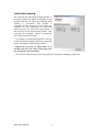
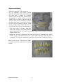
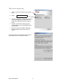
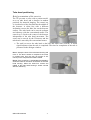
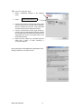
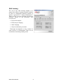
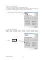
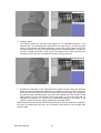
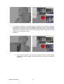
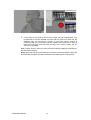
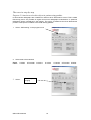
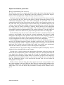
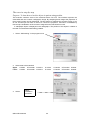
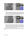
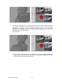
QBION ORAL RADIOLOGY
PACKAGE
User manual
OBJECT LOCALISATION
Contents
Contents.............................................................................................................................2
Object localisation.............................................................................................................3
Interaction training........................................................................................................4
Object positioning......................................................................................................5
Tube head positioning...............................................................................................7
Skill training..................................................................................................................9
Projection analysis...................................................................................................10
Fluoroscopic imaging..............................................................................................15
Static imaging..........................................................................................................19
Object localisation procedure..................................................................................24
Examination.................................................................................................................31
Qbion AB© 2009-06
2
Object localisation
Object localisation is one of four programs in Qbion Oral Radiology Package (QORP).
The overall aim of the program is to provide an environment for skill training in the
interpretation of spatial information in intraoral radiographs utilising parallax. Training
is accomplished by performance and analysis of radiographic examinations of a virtual
patient.
Start the program by clicking at the OBJECT LOCALISATION icon.
The Standard edition of the program contains the two modules “Interaction training”
and “Skill training”. In the Extended edition a third module called “Examination” is
added.
Qbion AB© 2009-06
3
Interaction training
The aim with the interaction training module is
to acquire skills with which to navigate in and
interact with the VE where the radiology skill
training is performed. The module is
comprised of two separate exercises which are
designed for the acquisition of interaction
skills necessary for successful performance of
the exercises in the skill training module. Two
exercises are available; “Object positioning”
and “Tube head positioning”.
It is highly recommended that the exercises
in the interaction training module be performed
before entering the skill training module.
Repeat the exercises as many times as is
needed until you can easily control the tools
for navigation and interaction!
The effect of skill training will be jeopardised if interaction training is neglected.
Qbion AB© 2009-06
4
Object positioning
Brief presentation of the exercise
The VE presents a scene with a patient
model, a small white, and a small blue ball.
The white ball is situated in a random
position in the vicinity of the dental arches.
Occasionally, it can be partly or totally
Blue ball
situated inside a tooth. If it is impossible to
find the white ball, it probably is situated
inside a tooth (if so, restart the exercise).
The blue ball is positioned centrally in the
mouth of the patient model and can be White ball
moved by means of the conventional mouse.
• The task is first to discover where the
white ball is situated. If the ball cannot be
found immediately the scene must be moved by means of the 3D-mouse in order to
find the white ball.
• When the white ball is located, the blue ball shall be moved inside the white ball by
means of the conventional mouse. A sound signal indicates when the task is
completed. The time for completion of the task is presented in the dialogue window.
Hint: The task is easier to complete if the patient
is moved closer to the viewer than the starting
position.
Qbion AB© 2009-06
5
The exercise step-by-step
1. Select: “Interaction training” in the program
menu
2. Select:
Object positioning
3. Use the 3D-mouse to change the view of the
scene. By doing this you can localise the
white ball situated somewhere among the
teeth.
4. Use the conventional mouse (right and
central button) to move the blue ball inside
the white ball.
5. When you have succeeded in placing the
blue ball inside the white ball a beep is
heard.
Short instructions and feedback are presented in
the dialogue window on the right monitor
Qbion AB© 2009-06
6
Tube head positioning
Brief presentation of the exercise
The VE presents a scene with a patient model,
an x-ray tube head, and a detector in random
positions for intraoral imaging. The central ray
is visualised as a blue line that hits the middle of
the detector. A white line with a different
inclination crosses the blue line on the detector
surface. The tube head can be moved up/down
and sideways with the conventional mouse. The
central ray is fixed to the centre of the detector
independent of the tube head movement. The
scene can be moved by the 3D-mouse and the
tube head is moved by the conventional mouse.
• The task is to move the tube head so the blue and white lines coincide. A sound
signal indicates when the task is completed. The time for completion of the task is
presented in the dialogue window.
Hint 1: Grasp the back of the tube head housing and
move it. The task is easier to complete if the scene
in pushed away from the user (by means of 3Dmouse) so the complete tube head is visible.
Hint 2: If the central ray is extrapolated backwards it
would be visible in the centre of the back of the tube
head housing. When the white line crosses the
middle of the tube head housing it would coincide
with the central ray.
Qbion AB© 2009-06
7
The exercise step-by-step
1. Select: “Interaction training” in the program
menu
2. Select:
Tube head positioning
3. Use the 3D-mouse to change the view of the
scene so that you can see the relation between
the blue central ray from the x-ray tube head
and the white line from different directions.
4. Use the conventional mouse (right button) to
position the x-ray tube head so the blue central
ray coincides with the white line (the white line
penetrates the centre of the back wall of the
tube head housing).
5. When the blue central ray coincides with the
white line a beep is heard indicating a
successful attempt.
Short instructions and feedback are presented in the
dialogue window on the right monitor.
Qbion AB© 2009-06
8
Skill training
The aim of the skill training module is to
acquire the skills to interpret spatial relations
in pairs of radiographs utilising parallax (a
shorter expression is “Object localisation”).
There are four exercises available focusing on
different aspects of the procedure. The
exercises are:
• Projection analysis
• Fluoroscopic imaging
• Static imaging
• Object localisation procedure
Thorough investigation of the content in
each exercise is recommended. There are no
restrictions concerning training order.
Qbion AB© 2009-06
9
Projection analysis
Brief presentation of the exercise
The aim of the exercise is to acquire the skill to deduce change in projection angle by
analysis of the relative position of anatomy details visible in the radiographs.
Each task starts by displaying the scene with the patient model. The detector position
is pre-selected by the user, and the tube head is directed toward the detector for an
orthoradial projection. A radiograph rendered from the individual positions of the
detector and tube head relative to the patient is displayed.
In the next step, an eccentric radiograph over the same area is displayed. The
projection angle for the eccentric image is randomly chosen by the software. However,
the new position of the tube head and detector (which also has moved a little) is not
visualised in the scene. The task is now to analyse how the relative positions of anatomy
details depicted in the radiographs have changed between the two radiographs. The
analysis requires knowledge in topographic anatomy and understanding of the parallax
principles. From the analysis it is possible to deduce the difference in projection
between the two radiographic images.
In the following step the user moves the tube head from the original position to the
position from which the eccentric radiograph was exposed. A third radiograph reflecting
the actual position of the tube head will be displayed when the user has moved the tube
head to the new position and made an “exposure”. Feedback is given as angulation error
and as visual comparison of the three radiographs.
If the angulation error is too large the user has to correct the tube head position. In
that case two feedback functions are available to guide the user. The first function is the
third radiograph which is displayed in fluoroscopic mode upon movement of the tube
head. The second is the red “bandy ball” which in a stylised way continuously indicates
the central ray direction for each of the displayed radiographs.
Qbion AB© 2009-06
10
The exercise step-by-step
Purpose: To learn how to analyze the projection geometry.
The simulator exposes one orthoradial and one eccentric image. By studying the images you
can figure out the eccentric projection. The task is to expose a similar image.
1. Select: “Skill training” in the program menu.
2. Select area to be examined
Upper
Lower
O Molar
O Molar
3. Select:
O Premolar O Canine
O Premolar O Canine
O Incisor
O Incisor
Projection
analysis
Qbion AB© 2009-06
11
O Canine
O Canine
O Premolar O Molar
O Premolar O Molar
4. Starting position:
The exercise starts with the tube head aligned for an orthoradial projection of the
selected area. Two radiographs are presented on the right monitor. The left one (gray
frame) is the resulting orthoradial radiograph and the right image (white frame) is an
eccentric projection over the same area exposed from a random direction. Use the 3Dmouse to change the position of the scene to any desired view. Brief instructions are
presented in the instruction and feedback window on the right monitor.
5. Analyse the projections in the orthoradial and eccentric images. Study the anatomic
details and note the differences between their depictions in the two images. When you
think you know which projection has been used in the eccentric image, try to duplicate it
by positioning the tube head where you think it was situated when the eccentric image
was exposed. Use the conventional mouse (right button) to move the tube head. To
facilitate the procedure, the central ray is automatically aligned to the centre of the
detector. Expose your own image by pressing the “Proceed” button.
Hint: Grasp the back of the tube head housing and move it. The task is easier to complete if
the scene in pushed away from the user (by means of 3D-mouse) so the complete tube
head is visible.
Qbion AB© 2009-06
12
6. Your image is presented in a third window (blue frame). A fourth window presents a
read ball (the “bandy ball”) with three satellites of different colours. The gray satellite
represents the projection for the orthoradial image (gray frame). The white one
represents the projection used for the eccentric image (white frame) and the blue
represents your image (blue frame).
7. Evaluation
a. If your image is similar to the eccentric image the white and blue satellite
coincide and a beep is heard. This indicates that the exercise is successfully
completed.
Qbion AB© 2009-06
13
b. If your image is not similar to the eccentric image, the tube head position must
be adjusted so the blue satellite coincides with the white one. Note that the
feedback from the fluoroscopic function in the blue framed window is
coordinated with the movement of the blue satellite at the bandy ball. A beep is
heard when the tube head has been moved to the correct position and the
exercise is completed.
Hint 1: Move the tube head and note the fluoroscopically displayed radiograph in
the blue framed window
Hint 2: Move the tube head and follow the movement of the blue satellite. When the
blue and white satellites coincide the tube head has reached the correct position.
Qbion AB© 2009-06
14
Fluoroscopic imaging
Brief presentation of the exercise
The aim of the exercise is to acquire the skill to deduce the relative depth position of an
object displayed in pairs of radiographs when the difference in projection angle is
known.
Each task starts with a display of the scene with the patient model. The detector
position is pre-selected by the user, and the tube head is directed toward the detector for
an orthoradial projection. Two identical radiographs rendered from the individual
positions of the detector and tube head relative to the patient display an artificial round
radiopaque object situated in a random position in the jaw. The object is not visualised
in the scene. One of the radiographs is displayed in fluoroscopic mode.
When the tube head is moved the fluoroscopic image is continuously updated. It is
therefore possible to follow the change in relative position between object details in
real-time, and compare them with the initial image. The user is urged to move the tube
head and analyse the radiographic information and deduce the three dimensional
position of the sphere in the jaw.
In the next step, the user takes the blue sphere that appears in the oral cavity and
places it in the correct position in the jaw. When the blue sphere is positioned the
simulator immediately provides feedback by visualising the correct position of the
radiopaque object as a white sphere. The user can analyse the performance visually and
the distance error is given.
Qbion AB© 2009-06
15
The exercise step-by-step
Purpose: To learn how to localise objects in patients using parallax.
In this exercise radiographs are visualised in real time when tube head is moved. This is called
fluoroscopy and is not possible in regular clinical oral radiographic examinations. A spherical
radiopaque object is displayed in the images. The goal is to determine the three dimensional
position of the sphere in relation to the teeth utilising parallax.
1. Select: “Skill training” in the program menu
2. Select area to be examined
Upper
Lower
O Molar
O Molar
3. Select:
O Premolar O Canine
O Premolar O Canine
O Incisor
O Incisor
Fluoroscopic
imaging
Qbion AB© 2009-06
16
O Canine
O Canine
O Premolar O Molar
O Premolar O Molar
4. Starting position:
The exercise starts with the tube head aligned for an orthoradial projection of the selected
area. The resulting image is presented in two identical copies on the right monitor. A
radiopaque round object is visible in the radiograph. The radiopaque object is not yet
visualised in the oral cavity. The left radiograph (gray frame) is static. The right (white
frame) is fluoroscopically displayed.
Use the 3D-mouse to change the position of the scene to any desired view. Brief
instructions are presented in the instruction and feedback window on the right monitor.
5. Move the tube head in any desired direction by using the conventional mouse (right
button). To facilitate the procedure, the central ray is automatically aligned to the centre
of the detector. The right radiograph (white frame) will continuously change in
accordance with the projection changes. The left (gray frame) will remain unaffected.
Analyse the two images during the movement and try to figure out the position of the
radiopaque object in relation to adjacent roots. When you think you know the position of
the radiopaque object, finish the tube head movement in an eccentric projection.
Hint: Grasp the back of the tube head housing and move it. The task is easier to complete if the
scene in pushed away from the user (by means of 3D-mouse) so the complete tube head is
visible.
Qbion AB© 2009-06
17
6. Press the “Proceed” button to continue. A blue sphere is visualised in the oral cavity. Grab
it with the conventional mouse and move it to the position where you think the radiopaque
object is situated in relation to the teeth.
Hint: It is easier to position the blue sphere if the patient is pulled close to the viewer.
7. When you have positioned the blue sphere in the desired position, push the “Proceed”
button.
8. Now the radiopaque object is visualised as a white sphere in the oral cavity. You can see
how close to the correct position you placed the blue sphere. The distance between the
spheres is presented in millimetres in the instruction and feedback window on the right
monitor.
Qbion AB© 2009-06
18
Static imaging
Brief presentation of the exercise
The aim of the exercise is to acquire skill in deducing the relative depth position of an
object displayed in pairs of radiographs when the difference in projection angle is
known. This simulates the clinical situation when one observes an object in a
radiograph and wants to decide the position of the object by using the parallax
technique.
Each task starts by displaying the scene with the patient model. The area to be
examined is pre-selected by the user, and the tube head is directed toward the detector
from an orthoradial projection. An initial radiograph is rendered from the individual
positions of the detector and tube head relative to the patient. A round radiopaque object
representing a spherical object in a random position in the jaw is displayed in the
radiograph. The sphere is not visualised in the oral cavity.
In the next step, the user is asked to expose an eccentric radiograph. The user has to
decide a proper projection angle and move the tube head and expose a second
radiograph. Then the user is urged to analyse the radiographic information in the two
images and deduce the three dimensional position of the radiopaque object in the jaw.
In the next step, the user takes the blue sphere that appears in the oral cavity and
places it in the correct position in relation to the teeth. When continuing the exercise the
simulator gives immediate feedback by visualising the correct position of the
radiopaque object as a white sphere. The user can analyse the result visually and the
distance error is given.
Qbion AB© 2009-06
19
The exercise step-by-step
Purpose: To learn how to localise objects in patients using parallax.
This exercise simulates a real situation. In an exposed image you find an object and want to
determine its position relative the teeth. By exposing a second image with a projection of your
own choice as a complement to the first image you receive a pair of images from which
necessary information can be extracted. The simulated radiographs display a round radiopaque
object the position of which is to be determined utilizing parallax.
1. Select: “Skill training” in the program menu.
2. Select area to be examined
Upper
Lower
O Molar
O Molar
3. Select:
O Premolar O Canine
O Premolar O Canine
O Incisor
O Incisor
Static imaging
Qbion AB© 2009-06
20
O Canine
O Canine
O Premolar O Molar
O Premolar O Molar
4. The exercise starts with the tube head aligned for an orthoradial projection of the
selected area. The resulting image is presented in a window (gray frame) on the right
monitor. A radiopaque round object is visible in the radiograph. The radiopaque object
also exists in the patient model but is not yet visualised. Use the 3D-mouse to change
the position of the scene to any desired view. Brief instructions are presented in the
instruction and feedback window on the right monitor.
5. Move the tube head by using the conventional mouse (right button) for an eccentric
projection of the area. The central ray is automatically aligned to the centre of the
detector in order to facilitate the procedure.
Hint: Grasp the back of the tube head housing and move it. The task is easier to complete if the
scene in pushed away from the user (by means of 3D-mouse) so the complete tube head is
visible.
Qbion AB© 2009-06
21
6. Expose the eccentric image by pressing the “Proceed” button. Your image is presented
along with the first image. Analyse the two images and try to figure out the position of
the radiopaque object in relation to adjacent roots.
7. In the patient model you can see a blue sphere in the centre of the oral cavity. Use the
conventional mouse (central and right button) to position the blue sphere where you
think the radiopaque object is situated in the patient model.
Hint: It is easier to position the blue sphere if the patient is pulled close to the viewer.
8. When you have positioned the blue ball in the desired position, push the “Proceed”
button.
Qbion AB© 2009-06
22
9. Now the radiopaque object is visualised as a white sphere in the oral cavity. You can
see how close to the correct position you placed the blue sphere. The distance between
the spheres is presented in millimetres in the instruction and feedback window on the
right monitor.
Qbion AB© 2009-06
23
Object localisation procedure
Brief presentation of the exercise
The aim of the exercise is to acquire the skill to deduce the relative depth position of an
object displayed in pairs of radiographs when the difference in projection angle is
known. It is an amalgamation of the previously described exercises.
Each task starts by displaying the scene with the patient model. The detector position
is pre-selected by the user, and the tube head is directed toward the detector for an
orthoradial radiographic image. Two initial radiographs are presented. One is the
orthoradial projection of the selected area and the second is an eccentric projection over
the same area. The projection angle for the second image is randomly chosen by the
software, and a random minor change in detector position has also occurred. The task is
to analyse how the relative positions of anatomy details depicted in the radiographs
have changed between the two radiographs. The analysis requires knowledge in
topographic anatomy and understanding of the parallax principles. From the analysis it
is possible to deduce the difference in projection angle between the two radiographs.
In the following step the user moves the tube head from its original position to the
position it was thought to be in when the eccentric radiograph was exposed. A third
radiograph reflecting the actual position of the tube head will be displayed when the
user has moved the tube head to the new position and made an “exposure”. Feedback is
given as angulation error and as visual comparison of the three radiographs.
If the angulation error is too large the user has to correct the tube head position. In
that case two feedback functions become available to guide the user. The first function
is the third radiograph which is displayed in fluoroscopic mode upon movement of the
tube head. The second is the red “bandy ball” which in a stylised way continuously
indicates the central ray direction for each of the displayed radiographs.
When the difference in projection angle is established a spherical radiopaque object is
displayed in the orthoradial and eccentric images.
Next the user is urged to analyse the radiographic information in the two images and
deduce the three dimensional position of the sphere in the jaw. The bandy ball helps the
user identify the direction of the central ray of both the orthoradial and eccentric
projections when viewing the patient model. This function is helpful in the analysis of
the three dimensional position relative to the teeth as it helps the user view the teeth
(and the radiopaque object) in the actual beam direction that was used when the
radiographs were exposed.
Finally, the user takes the blue sphere that appears in the oral cavity and places it in
the correct position in the jaw. When the blue sphere is positioned the simulator gives
immediate feedback by visualising the correct position of the radiopaque object as a
white sphere. The user can analyse the performance visually and the distance error is
given.
Qbion AB© 2009-06
24
The exercise step-by-step
Purpose: To learn how to localise objects in patients using parallax.
This exercise combines some of the exercises above into one. The simulator exposes one
orthoradial and one eccentric radiographic image. By analysing these images the projection of
the eccentric image can be determined. The first task is to duplicate the eccentric image. If you
do not succeed you will have a chance to correct the projection. Correction is facilitated by
fluoroscopic visualisation of the eccentric image when the tube head is moved.
A radiopaque object is displayed in the radiographs. The position of this object in relation to
the teeth is to be determined utilising parallax.
1. Select: “Skill training” in the program menu
2. Select area to be examined
Upper
Lower
O Molar
O Molar
3. Select:
O Premolar O Canine
O Premolar O Canine
O Incisor
O Incisor
Object
localisation
procedure
Qbion AB© 2009-06
25
O Canine
O Canine
O Premolar O Molar
O Premolar O Molar
4. TASK 1
The exercise starts with the tube head aligned for an orthoradial projection of the
selected area. Two radiographs are presented on the right monitor. The left one (gray
frame) is the resulting orthoradial radiograph and the right image (white frame) is an
eccentric projection over the same area exposed from a random direction. Use the 3Dmouse to change the position of the scene to any desired view. Brief instructions are
presented in the instruction and feedback window on the right monitor.
5. Analyse the projections in the orthoradial and eccentric images. Study the anatomic
details and note the difference between their depictions in the two images. When you
think you understand the projection in the eccentric image try to duplicate it by
positioning the tube head where you think it was when the eccentric image was
exposed. Use the conventional mouse (right button) to move the tube head. To facilitate
the procedure, the central ray is automatically aligned to the centre of the detector.
Expose your own image by pressing the “Proceed” button.
Hint: Grasp the back of the tube head housing and move it. The task is easier to complete if the
scene in pushed away from the user (by means of 3D-mouse) so the complete tube head is
visible.
Qbion AB© 2009-06
26
6. Your image is presented in a third window (blue frame). A fourth window presents a
read ball (the “bandy ball”) with three satellites of different colours. The gray satellite
represents the projection for the orthoradial image (gray frame). The white one
represents the projection used for the eccentric image (white frame) and the blue
represents your image (blue frame).
7. EVALUATION 1
a. If your image is similar to the eccentric image the white and blue satellite coincide and
a beep is heard. This indicates that the exercise is successfully completed. Press the
“Proceed” button to continue in the exercise.
Qbion AB© 2009-06
27
b. If your image is not similar to the eccentric image, the tube head position must be
adjusted so the blue satellite coincides with the white one. Note that the feedback
from the fluoroscopic function in the blue framed window is coordinated with the
movement of the blue satellite of the bandy ball. A beep is heard when the tube head
has been moved to the correct position and the exercise is completed. Press the
“Proceed” button to continue in the exercise.
Hint 1: Move the tube head and note the fluoroscopically displayed radiograph in the blue
framed window
Hint 2: Move the tube head and follow the movement of the blue satellite. When the blue and
white satellites coincide the tube head has reached the correct position.
8. TASK 2
In the patient model you can see a blue sphere in the centre of the oral cavity. Use the
conventional mouse (central and right button) to position the blue sphere where you
think the radiopaque object is situated in the patient model.
Hint 1: It is easier to position the blue sphere if the patient is pulled close to the viewer.
Qbion AB© 2009-06
28
Hint 2: Observe that you can use the 3D-mouse to place the gray satellite in the centre of the
cross hairs seen over the bandy ball. By doing this, you can view the patient model in exactly
the same projection that was used when the orthoradial image (gray frame) was exposed. If you
place the white ball in the centre of the cross hairs you can view the patient model in exact the
same projection in which the eccentric x-ray image (white frame) was exposed.
9. When you have positioned the blue ball in the desired position, push the “Proceed”
button.
Qbion AB© 2009-06
29
10. EVALUATION 2
Now the radiopaque object is visualised as a white sphere in the oral cavity. You can
see how close to the correct position you placed the blue sphere. The distance between
the spheres is presented in millimetres in the instruction and feedback window on the
right monitor.
Qbion AB© 2009-06
30
Examination
The “Examination” module is designed to automatically and objectively evaluate the
user’s knowledge and understanding of the object localisation procedure. The module is
under construction.
Qbion AB© 2009-06
31