1
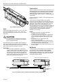
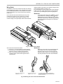
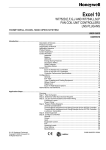
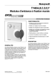
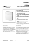
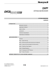
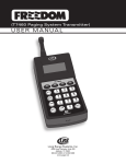
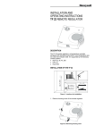
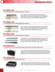
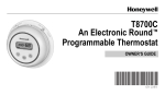
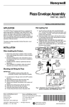
�������� W7752D,E,F,G,J FAN COIL UNIT CONTROLLERS ������������������������� ������������������� The Excel 10 Fan Coil Unit (FCU) Controller is available in the following five models: 1. W7752D2007 —230 Vac power with electric reheat relay. 2. W7752E2004 —230 Vac power without electric reheat relay. 3. W7752F2002 —115 Vac power with electric reheat relay. 4. W7752G2000 —115 Vac power without electric reheat relay. 5. W7752J2003 —100 Vac power without electric reheat relay. The models all have identical housings and mounting procedures. ��������� ���������������������������������������������� ������������������������������������������������� �������������������������������������������������� ������������������������������������������� �������������������������������������������� ������������������������������������������������� ���������������������������������������������������� ����������������������������������� ������������ Mount the Fan Coil Unit controllers in locations that allow clearance for wiring. The controllers can be mounted on a panel with screws or by snapping onto standard EN 50 022 DIN rail, 1-3/8 by 9/32 in. (35 mm by 7.5 mm). See Fig. 1 for mounting dimensions. See Fig. 2 for DIN rail mounting. The type and length of screw required for screw mounting depends upon the panel material used to mount the controller. The controller can be mounted either vertically or horizon tally. However, if thermal actuators are connected to the controller outputs, it is recommended that the controller be mounted so that the transformer is not located beneath the electronics. �������� ������������������������ Source power at terminal block can cause personal injury or death. W7752 FCU Controllers must be mounted inside their respective fan coil unit boxes to prevent access by unauthorized personnel. To reduce the risk of fire or electric shock, install in a controlled environment relatively free of contaminants. ������ All wiring must comply with applicable electrical codes and ordinances. Refer to job or manufacturers’ drawings for details. �������������������������������������������������������������������������������������� ® U.S. Registered Trademark Copyright © 1999 Honeywell Inc. All Rights Reserved 95- 7519- 3 ���������������������������������������� �������������� Wire the controller communications E-Bus using level IV 22 AWG (Belden part number 9D220150) or plenum-rated level IV 22 AWG (Belden part number 9H2201504) nonshielded, twisted pair, solid conductor wire. When possible, use Honeywell AK3781, AK3782, AK3791, or AK3792 cable (US part numbers). Pull the cable to each controller on the E-Bus and connect to terminals 9 and 10. The W7752 FCU Controller utilizes a free topology transceiver (FTT10A) E-Bus which allows daisy-chain, loop, and star network configurations or any combination thereof. Depending upon the E-Bus configuration used, one or two termination modules, part number 209541B, may be required. Different connections to the termination module are necessary depending upon whether it is used in a singly- or doubly-terminated network configuration. See Excel 10 FTT/LPT 209541B Termination Module Installation Instructions, form 95-7554. �������������������������� ����� Input power provided must be 230 Vac (+10%, -15%), 50 or 60 Hz for W7752D and E; 115 Vac (+10%, -15%), 50 or 60 Hz for W7752F and G, and 100 Vac (±6%), 50 or 60 Hz for W7752J. ������ — The E-Bus is insensitive to polarity, eliminating installation errors due to miswiring. — Do not bundle output wires with sensor, digital input or communications bus wires. Maintain a minimum 3 in. (76 mm) separation between E-Bus and Triac output wiring. — For installations, try to avoid areas of high electromagnetic noise (EMI). — Some T7770 Wall Modules used for 2000-series FCU controllers have a daisy-chain connection for the E-Bus to provide network access via built-in jack. — For more information see E-Bus Wiring Guidelines, form number 74-2865. �������� Turn off power prior to connecting to or removing connections from any terminals to avoid electrical shock or equipment damage. Use the heaviest gauge wire available, up to 14 AWG (2.5 2 2 mm ) with a minimum of 18 AWG (1.0 mm ) for all power wiring. Strain relief/support must be provided for power wiring within 2-3/8 in. (60 mm) of controller connection. ������������ ��������� �������������������������������������������� �������������������������������������������������� �������������������������������������������������� ������������������������������������������������ ������������������������������������������������� ���������������������������������������������������� ����������������������������������������� A variety of Excel 10 wall modules can be used with W7752 FCU Controllers. See T7460 Wall Modules Installation Instructions, form number 95-7610; T7560 Digital Wall Module Installation Instructions, form number 95-7620; and T7770 Wall Modules Installation Instructions, form number 95-7538 for installation details. W7752 FAN COIL UNIT CONTROLLER W7752 FAN COIL UNIT CONTROLLER 9 10 11 12 9 10 11 12 TERMINATION MODULE �������������������������������������������������������������������������� 95-7519-3 2 ���������������������������������������� �������������� interface cables is 65 ft (20 m). The maximum length for fan power switching cables is 3 1/2 ft (1 m). Fig. 6 illustrates the terminal assignments of the controllers. Table 1 lists Triac output assignments for various actuator types. Refer to job drawings for specific wiring diagrams. Connections to the FCU controllers are made at 2 terminal blocks protected by a plastic cover. W7752D and F models have 2 additional terminals on terminal block 2 for electric reheat connections. Fig. 4 shows removal of the terminal block cover. ��������� ������������������������������������������������� � ������������������������������� ������������ � �������������������������������������� �������� ������������������������������������������������������ ��������������������������������������������������� ��������������� 2 Use a minimum wire size of 20 AWG (0.5 mm ) for all input/output connections. Use a minimum of 16 AWG 2 (1.5 mm ) for electric reheat output connections. The maximum length of all input/output cables and wall module ������������������������������� ��������� ������������������������������������������������ ���������������������������������������������� ������������������������������������������������ �������������������������������������������������� ��������������������������������������������� Wire to the terminal blocks as follows: �� Strip 1/2 in. (13 mm) insulation from the conductor. �� Insert the wire in the required terminal location and tighten the screw to complete the termination. �� If two or more wires are being inserted into one terminal location, twist the wires together before inserting them. 1. STRIP 1/2 IN. (13 MM) FROM WIRES TO BE ATTACHED AT ONE TERMAINAL 2. TWIST WIRES TOGETHER WITH PLIERS (A MINIMUM OF THREE TURNS). 3. CUT TWISTED END OF WIRES TO 3/16 IN. (5 MM) BEFORE INSERTING INTO TERMINAL AND TIGHTENING SCREW. THEN PULL ON EACH WIRE IN ALL TERMINALS TO CHECK FOR GOOD MECHANICAL CONNECTION. ������������������������������������������������������� 3 95-7519-3 ���������������������������������������� ������������������������������ OCCUPANCY SENSOR CHANGEOVER CONTACT AIRFLOW CONTACT WINDOW CONTACT MOTION SENSOR WALL MODULE CONNECTIONS LONWORKS NETWORK IN LONWORKS NETWORK OUT + HEAT - COM OPEN CLOSE COM OPEN CLOSE COOL FAN DGND DIGITAL INPUT 19 20 21 22 23 24 25 26 RELAY COM RELAY 1 RELAY 2 RELAY 3 SUPPLY VOLT SUPPLY VOLT PWR RELAY IN (D,F MODELS ONLY) PWR RELAY OUT (D,F MODELS ONLY) LED SETPOINT FAN / BYPASS TEMP SENSOR AGND E-BUS IN E-BUS IN E-BUS OUT E-BUS OUT OUT 1 COM OUT 1 OPEN OUT 1 CLOSE OUT 2 COM OUT 2 OPEN OUT 2 CLOSE 4A LO MED HI POWER MAINS REHEAT + 1 2 3 4 5 6 7 8 9 10 11 12 13 14 15 16 17 18 RETURN 0.5A L N 16A �������������������������������������������� ������������������������������������������������������� ����������� Floating 1-stage 2-stage 3-stage PWM Thermal �������������� �� �� open close on/off — stage 1 stage 2 stage 1 stage 2 stage 3 24 Vac PWM — 24 Vac on/off — �� 24 Vac 24 Vac 24 Vac 24 Vac �������������� �� �� open close on/off — stage 1 stage 2 stage 1 stage 2 stage 3 24 Vac PWM — 24 Vac on/off — �� 24 Vac 24 Vac 24 Vac 24 Vac ������������������������� ������������������������� ���������������������������������� Honeywell Inc. Honeywell Plaza P.O. Box 524 Minneapolis, MN 55408-0524 USA http://www.honeywell.com Honeywell Limited-Honeywell Limitee 155 Gordon Baker Road North York, Ontario M2H 3N7 Canada http://www.honeywell.ca Honeywell AG Böblinger Straβe 17 D-71101 Schönaich Germany 95-7519-3 Rev. 6-99 7157 234 http://europe.hbc.honeywell.com printed in U.S.A. Subject to change without notice