1
ZAPP
W7070A1000 RECEIVER
SYSTEM ENGINEERING
CONTENTS
INTRODUCTION...................................................................................................................................................... 3
Description of Devices .............................................................................................. 3
Organization of Manual............................................................................................. 3
Agency Listings......................................................................................................... 3
Construction.............................................................................................................. 3
Performance Specifications ...................................................................................... 4
Abbreviations and Definitions ................................................................................... 5
APPLICATION STEPS ............................................................................................................................................ 6
Overview ................................................................................................................... 6
Step 1. System Planning........................................................................................... 6
Step 2. Determining What Other Bus Devices Are Required.................................... 6
Step 3. Laying Out Communications and Power Wiring ........................................... 7
Step 4. Preparing Wiring Diagrams .......................................................................... 9
Step 5. Ordering Equipment ................................................................................... 10
Step 6. Configuring the ZAPP Receiver.................................................................. 10
Step 7. Teach-in Procedure .................................................................................... 11
APPENDIX. COMPLETE LIST OF ZAPP NETWORK VARIABLES ..................................................................... 12
® U.S. Registered Trademark
Copyright © 2001 Honeywell Inc.
All Rights Reserved
EN0B-0286GE51 R1101
ZAPP RECEIVER SYSTEM ENGINEERING
EN0B-0286GE51 R1101
2
ZAPP RECEIVER SYSTEM ENGINEERING
INTRODUCTION
Description of Devices
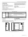
The ZAPP receiver forwards commands from the ZAPP
handheld(s) to devices on the LONW ORKS® network. The
ZAPP receiver is suitable for either wall mounting or unit
mounting.
Organization of Manual
The Introduction and Application Steps 1 through 7 provide the
information needed to make accurate ordering decisions.
These steps are guidelines intended to aid understanding of
the product I/O options, bus arrangement choices, configuration options, and ZAPP's role in the overall EXCEL 5000
System architecture.
Agency Listings
Table 1 provides information on agency listings for ZAPP
products.
This manual is organized to guide you through the engineering
of a project from start to finish. If you are adding to or
changing an existing system, the Table of Contents guides you
to the relevant information.
Table 1. Agency listings.
Device
ZAPP
Agency
CE
FCC
Comments
General Immunity per European Consortium standards EN50081-1 (CISPR 22 Class B) and
EN 50082-1:1992 (based on Residential, Commercial, and Light Industrial).
EN 61000-4-2
IEC 1000-4-2 (IEC 801-2) Electromagnetic Discharge.
EN 50140, EN 50204
IEC 1000-4-3 (IEC 801-3) Radiated Electromagnetic Field.
EN 61000-4-4
IEC 1000-4-4 (IEC 801-4) Electrical Fast Transient (Burst).
Radiated Emissions and Conducted Emissions.
EN 55022:1987 Class B.
CISPR-22: 1985.
Complies with requirements in FCC Part 15 rules for a Class B Computing Device.
CAUTION
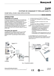
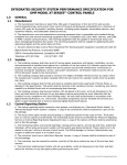
Construction
ZAPP Receiver
The ZAPP receiver is available in one basic model. ZAPP is
powered by 24 Vac. All wiring connections are made at screw
terminal blocks accessible beneath a plastic cover. Mounting
dimensions are shown in Fig. 1.
Turn off power prior to connecting to or removing connections
from any terminals to avoid electrical shock or equipment
damage.
Fig. 1. ZAPP construction in inches (mm).
3
EN0B-0286GE51 R1101
ZAPP RECEIVER SYSTEM ENGINEERING
Performance Specifications
2.
Power Supply
24 Vac ± 20 %, 50/60 Hz, max. 2 VA.
3.
Operating Temperature
(0 ° to 40 °C).
4.
nv1
nvoStatus
SNVT_obj_status
nv3
nviTeachActivate
SNVT_count
nv2
nvoRFState
Non_SNVT
nv4
nciRmConfig
config Non_SNVT
nv6
nvoSetptOffset1
SNVT_temp_p
nv5
nciSndHrtBt
config SNVT_time_sec
nv7
nvoFanSpeedCmd1
SNVT_switch
nv8
nvoOccManCmd1
SNVT_occupancy
nv9
nvoLampManPos1
SNVT_switch
Relative Humidity
5 % to 95 % noncondensing
IMPORTANT!
When any device is energized by a Triac, the device
must be able to sink a minimum of 15 mA. If nonHoneywell motors, actuators, or transducers are to be
used with ZAPP, compatibility must be verified.
6.
nviRequest
SNVT_obj_request
Shipping/Storage Temperature
(-35 ° to 65 °C).
5.
nv0
nvoSblndManPos1
nv10 SNVT_Setting
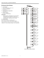
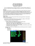
Interoperability
ZAPP uses the Echelon® LonTalk® protocol.
nvoFreeUse1
nv11 SNVT_switch
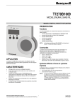
Fig 2. shows the input and output variables of ZAPP.
nvoSpaceTemp1
nv12 SNVT_temp_p
Table 2 provides you with an overview of the ZAPP network
variables. For a more-detailed description, see the Appendix.
nvoSetptOffset2
nv13 SNVT_temp_p
nvoFanSpeedCmd2
nv14 SNVT_switch
nv20
nv20
nvoSetptOffset3
SNVT_temp_p
nvoSetptOffset4
nv27
nv27
SNVT_temp_p
nvoSetptOffset5
nv34 SNVT_temp_p
nvoSetptOffset6
nv41 SNVT_temp_p
nvoSetptOffset7
nv48 SNVT_temp_p
nvoSetptOffset8
nv55 SNVT_temp_p
Fig. 2. Input and output variables
EN0B-0286GE51 R1101
4
ZAPP RECEIVER SYSTEM ENGINEERING
Abbreviations and Definitions
LONWORKS® network
Network for communication among different ZAPPs.
Echelon®
The company that developed the LONW ORKS®
network and the Neuron Chips used to communicate
on the LONW ORKS® network.
NEMA
National Electrical Manufacturers Association. An
organization of companies which has developed safe
field-wiring practices and standards.
NV
Network Variable. A ZAPP parameter that can be
viewed or modified over the LONW ORKS® network.
NVI
Network input variable
NVO
Network output variable
EMI
Electromagnetic Interference. Electrical noise that
can cause problems with communication signals.
FTT
Free Topology Technology
PC
Personal Computer.
ID
Identification
RF
Radio frequency
I/O
Input/Output. The physical sensors and actuators
connected to a ZAPP.
VA
Volt-Amperes. A measure of electrical power output
or consumption as applicable to an ac device.
K
Kelvin.
Vac
NEC
National Electrical Code. The body of standards for
safe field-wiring practices.
Voltage alternating current. ac voltage as opposed to
dc voltage.
5
EN0B-0286GE51 R1101
ZAPP RECEIVER SYSTEM ENGINEERING
APPLICATION STEPS
Step 2. Determining What Other Bus Devices
Are Required
Overview
A maximum of 62 nodes can communicate on a single
LONW ORKS® network segment. If more nodes are required, a
router is necessary.
Steps one through seven describe ZAPP's engineering. These
steps are guidelines intended to aid understanding of the
product I/O options, bus arrangement choices, configuration
®
options and ZAPP's role in the overall EXCEL 5000 System
architecture.
Step No.
Using a router allows up to 125 nodes, divided between two
LONW ORKS® network segments. The router accounts for two
of these nodes (one node on each side of the router).
Description
1
Planning the System
2
Determining Other Bus Devices Required
3
Laying out Communication and Power Wiring
4
Preparing Wiring Diagrams
5
Ordering Equipment
6
Configuring ZAPP
7
Teaching-in
The maximum length of an FTT LONW ORKS® network segment
is 1,400 m for a daisy chain configuration or 500 m total wire
length and 400 m node-to-node for any other type of configuration.
NOTE: For FTT LONW ORKS® network segments, the
distance from each transceiver to all other
transceivers and to the termination module must not
exceed the maximum node-to-node distance. If
multiple paths exist, the longest one should be used
for the calculation.
If longer runs are required, add a router to partition the system
into two segments. In addition, all LONW ORKS® network
segments require the installation of a Bus Termination Module.
Step 1. System Planning
Plan the use of ZAPP according to the job requirements.
Determine the location, functionality, and sensor or actuator
usage. Also check the number and type of output actuators
and other accessories required.
For an FTT LONW ORKS® network segment, one or two
Termination Modules may be required, depending upon the
bus configuration.
When planning the system layout, consider potential expansion possibilities to allow for future growth. Planning is very
important to be prepared for adding HVAC systems and
ZAPPs in future projects.
NOTE: The ZAPP handheld unit and the ZAPP receiver to
which it has been allocated should not be blocked by
more than one intervening wall and one intervening
story, nor should be they be separated by a distance
of more than 30 meters. The possible effects of
massive metal structures (steel beams, metal panels,
etc.) located between the ZAPP handheld and the
ZAPP receiver should be taken into consideration.
Further, no two ZAPP receivers should be stationed
nearer than 0.5 meter to each other.
The LONW ORKS® network communication loop between ZAPP
receivers and handhelds must be laid out according to the
guidelines applicable for that topology.
ZAPP uses FTT technology, which allows daisy chain, star,
loop or combinations of these bus configurations.
It is important to understand the interrelationships between
ZAPP and other LONW ORKS® devices in the network early in
the job engineering process to ensure their implementation
when configuring the ZAPP receiver.
EN0B-0286GE51 R1101
6
ZAPP RECEIVER SYSTEM ENGINEERING
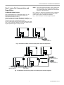
Step 3. Laying Out Communications and
Power Wiring
NOTE: Due to the transformer isolation, the bus wiring does
not have a polarity. It is not important which of the
two LONW ORKS® network terminals are connected to
each wire of the twisted pair.
LONWORKS® network Layout
Fig. 3. and Fig. 4. depict two typical daisy chain LONW ORKS®
network layouts; one as a single bus segment that has 60
nodes or less, and one showing two segments.
The communications bus, LONW ORKS® network, is a 78Kbaud serial link that uses transformer isolation and
differential Manchester encoding.
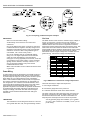
Fig. 5. shows examples of free topology bus layouts.
Wire the LONW ORKS® network using level IV 22 AWG or
plenum rated level IV 22 AWG nonshielded, twisted pair, solid
conductor wire as the recommended wire size.
An FTT LONW ORKS® network can be wired in daisy chain, star,
loop, or any combination thereof as long as the maximum wire
length requirements given in Step 2 are met.
5
6
7
8
5
6
7
8
BROWN
ORANGE
TERMINATION
MODULE (209541B)
Fig. 3. Termination module connection (daisy-chain network configuration).
5
6
7
8
5
6
7
8
UP TO 60
TOTAL NODES
LONW ORKS R OUTER
5
6
7
8
TERMINATION
MODULE (209541B)
5
6
7
8
TERMINATION
MODULE (209541B)
TERMINATION
MODULE (209541B)
UP TO 60
TOTAL NODES
Fig. 4. LONWORKS® network wiring layout for two daisy-chain network segments.
7
EN0B-0286GE51 R1101
ZAPP RECEIVER SYSTEM ENGINEERING
Fig. 5. Free topology LONWORKS® layout examples.
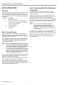
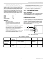
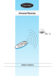
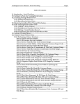
Line Loss
IMPORTANT!
Notes on Communications Wiring:
The ZAPP receiver must receive a minimum supply voltage of
20 Vac. If long power or output wire runs are required, a
voltage drop due to Ohm's Law (I x R) line loss must be considered. This line loss can result in a significant increase in
total power required and thereby affect transformer sizing. This
means that some volts will be lost between the transformer
and the ZAPP receiver. Because all transformer output voltage
levels depend on the size of the connected load, a larger
transformer outputs a higher voltage than a smaller one for a
given load. Fig. 6 shows this voltage load dependence.
All field wiring must conform to local codes and
ordinances.
Do not use different wire types or gauges on the same
LonWorks® network segment. The step change in line
impedance characteristics would cause unpredictable
reflections on the bus. When using different types is
unavoidable, use a router at the junction.
Do not use shielded cable for LonWorks® network
wiring runs. The higher capacitance of the shielded
cable will cause degradation of communications
throughput. In noisy (high EMI) environments, avoid wire
runs parallel to noisy power cables, or lines containing
lighting dimmer switches, and keep at least 3 in. (76
mm) of separation between noisy lines and the
LonWorks® network cable.
27
26
25
SECONDARY VOLTAGE
24
Make sure that neither of the LONWORKS® network wires
is grounded.
23
22
21
20
19
18
17
Power Wiring
16
15
A power budget must be calculated for each ZAPP receiver to
determine the required transformer size for proper operation.
A power budget is simply the summing of the maximum power
draw ratings (in VA) of all the devices to be controlled by
ZAPP. This includes the ZAPP receiver itself, the equipment
and various contactors and transducers, as appropriate, for
the configuration. For contactors and similar devices, the inrush power ratings should be used as the worst-case values
when performing power budget calculations. Also, the
application engineer must consider the possible combinations
of simultaneously energized outputs and calculate the VA
ratings accordingly. The worst case that uses the largest
possible VA load should be determined when sizing the
transformer.
14
0
100
% OF LOAD
200
150
M993
Fig. 6 NEMA class 2 transformer voltage output limits.
There are three ways to adjust the output level:
1. Use a larger transformer.
2. Use heavier gauge wire for the power run.
3. Locate the transformer closer to the ZAPP receiver.
The issue of line loss is also important in the case of the output wiring connected to the Triac digital outputs. The same
formula and method are used. The rule to remember is to
keep all power and output wire runs as short as practical.
IMPORTANT!
Use the heaviest gauge wire available, up to 14 AWG
2
2
(2.0 mm ), with a minimum of 18 AWG (1.0 mm ) for all
power wiring.
The installation must be designed to allow for a line loss
of no greater than two volts, thus guaranteeing nominal
EN0B-0286GE51 R1101
50
8
ZAPP RECEIVER SYSTEM ENGINEERING
operation if the primary voltage drops to 102 Vac (120
Vac minus 15 %) or 193 Vac (230 minus 15 %).
To meet the National Electrical Manufacturers Association
(NEMA) standards, a transformer must stay within the NEMA
limits. Fig. 6 shows this voltage load dependence. With 100
percent load, the transformer secondary must supply between
23 and 25 volts to meet the NEMA standard. When a purchased transformer meets the NEMA standard DC20-1986,
the transformer voltage-regulating ability can be considered
reliable. Compliance with the NEMA standard is voluntary. The
following Honeywell transformers meet this NEMA standard:
Transformer Type
AT20A
AT40A
AT72D
AT87A
AK3310 Assembly
Unswitched 24 Vac power wiring can be run in the same
conduit as the LONWORKS® network cable.
To minimize EMI noise, do not run Triac and/or relay
output wires in the same conduit as the input wires of
the LONWORKS® network communications wiring.
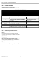
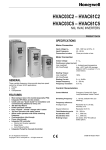
Step 4. Preparing Wiring Diagrams
General Considerations
The purpose of this step is to assist the application engineer in
developing job drawings to meet job specifications. Wiring
details for the ZAPP receiver are shown in Fig. 7. Table 3 lists
wiring types, sizes, and length restrictions for ZAPP products.
VA Rating
20
40
40
50
100
LONWORKS® Termination Module
One or two LONW ORKS® network Termination Modules, part
no. 209541B, are required for a LONW ORKS® network with FTT
devices on it, depending upon the configuration. Double termination is required only when the network is a daisy-chain
configuration and the total wire length is greater than 1640 ft
(500 m). The maximum lengths described in Step 2 must be
adhered to for either a daisy chain or free topology
LONW ORKS® network layout.
IMPORTANT!
Notes on power wiring:
All field wiring must conform to local codes and
ordinances or as specified on installation wiring
diagrams.
To maintain NEC Class 2 and UL ratings, the installation
must use transformers of 100 VA or less capacity.
In the case of multiple ZAPP receivers operating from a
single transformer, the same side of the transformer
secondary must be connected to the same input
terminal on each ZAPP receiver.
24 VAC
24 VAC COM
120/240 VAC
The ZAPP receiver has Triac outputs; all output devices
must therefore be powered from the same transformer
as the one powering the ZAPP receiver.
LONWORKS NETWORK IN
LONWORKS NETWORK OUT
1
2
24 V AC
24 V AC
3
4
5
24 V AC
24 V AC
6
7
8
LONWORKS
LONWORKS
LONWORKS
LONWORKS
Fig. 7. ZAPP wiring example
Table 3. Field wiring references
Wire Function
LONW ORKS®
Recommended
Minimum Wire Size
AWG (mm2)
Construction
Specification or
Requirement
Vendor Wire
Type
22 AWG
Twisted pair solid
conductor, nonshielded
Level IV 60 °C rating
Europe: Belden
9H2201504
22 AWG
Twisted pair solid
conductor, nonshielded
Level IV 60 °C rating
Europe: Belden
9D220150
14 AWG
Any pair nonshielded (use
heavier wire for longer
runs)
NEC Class 2
60 °C rating
network (Plenum)
LONW ORKS®
network
(Nonplenum)*
Power Wiring
(2.5 mm2)
Maximum Length
ft (m)
Limited by line loss
effects on power
consumption.
NOTE: PVC wire must not be used where prohibited by local fire regulations.
9
EN0B-0286GE51 R1101
ZAPP RECEIVER SYSTEM ENGINEERING
Step 5. Ordering Equipment
Order equipment after compiling a bill of materials through
completion of the previous application steps.
Table 4. ZAPP Ordering Information
Part Number
Product Description
ZAPP receiver
Comments
W7070 A 1000
RT 70-HRD20-Wall
RT 7070A 1008
209541B
—
Belden 9H2201504
(Europe)
Belden 9D220150
(Europe)
CARE-CD
ZAPP handhelds
Wall holder for handhelds
Echelon®-Based Components and Parts
FTT Termination Module
Cabling
Serial Interface Cable, male DB-9 to female DB-9 or
female DB-25
LONW ORKS® network (plenum): 22 AWG twisted pair
solid conductor, nonshielded
LONW ORKS® network (non-plenum): 22 AWG twisted
pair solid conductor, nonshielded
CD-ROM
Contains all of the DRF's (Data Resource Files) which
you will need to adjust the configuration of the network
variables.
Step 6. Configuring the ZAPP Receiver
General
The configuration process involves providing the ZAPP
receiver with information using the LonMaker™ tool (or other
LNS-based tool).
Commissioning
Commissioning refers to the activities performed to install the
ZAPP receiver on the LONW ORKS Network. The ZAPP
receiver is preconfigured at the Factory; a LonMaker Plug-In
for configuration is therefore not required.
ID Number
Each ZAPP receiver is shipped with a unique internal
©
Identification Number from the factory called the Neuron ID.
EN0B-0286GE51 R1101
10
Set of 10.
Two required per LONW ORKS® network
segment.
Obtain locally from any computer
hardware vendor.
Level IV 60 °C rating.
Level IV 60 °C rating.
At present, no plug-ins are available.
ZAPP RECEIVER SYSTEM ENGINEERING
Step 7. Teach-in Procedure
4.
Teach-in is a procedure required to allocate
ZAPP handhelds and/or wall modules to the
ZAPP receiver. Up to eight handhelds and/or wall
modules can be allocated to a single ZAPP
receiver. After successful completion of the
teach-in procedure, the ZAPP receiver will
recognize commands from the given handheld(s)
and/or wall module(s). The following procedure
must be performed for each individual handheld
and/or T7270 wall module.
NOTE: Continuing to hold down the button for
an additional 5 seconds will again
disable T7270 reception (valid only in
the case of Version 1.10 and higher).
1.
Enable T7270 reception by pressing and
holding down the teach-in button on the
ZAPP receiver for 20 seconds after
power-up.
NOTE: T7270 reception is disabled, by default.
Enabling it will automatically delete all
previously stored teach-ins!
Enable the teach-in mode of the ZAPP
receiver.
a) Press the button on the ZAPP receiver for
at least two seconds.
"TEACH" is displayed, thus indicating that the
ZAPP receiver is now in the teach-in mode.
After you have successfully completed the
wall module teach-in procedure (indicated by
the ZAPP receiver displaying "OK") and
enabled T7270 reception, the ZAPP receiver
will recognize commands from the wall
module. A symbol ( ) for incoming
commands (if any) from the wall module will
be displayed in the upper right-hand corner of
the status display next to the room number.
NOTE: If you enter no input within 3 minutes,
the ZAPP receiver will revert back to the
normal mode.
2.
If teach-in has failed, no change is visible in
the display of the ZAPP receiver. After three
minutes, the ZAPP receiver returns to the
normal mode. To retry the teach-in
procedure, repeat points one through four.
Choose a unique number for the
handheld / wall module.
Because you can allocate up to eight handhelds
and/or eight wall modules to the ZAPP receiver,
you must give each handheld / wall module a
unique number. Thus, no two handhelds should
have the same number, nor should any two wall
modules have the same number. (however, a
handheld may have the same number as a wall
module).
a) Select a unique number (1 through 8) for
the given handheld / wall module by
pressing the button on the ZAPP receiver
as many times as is necessary.
The ZAPP receiver is now ready to receive
teach-in messages from the handheld / wall
module.
Teaching-in Additional Handhelds / Wall
Modules
It is possible to allocate up to eight handhelds
and/or eight wall modules to a single ZAPP
receiver. To do this, proceed as follows:
NOTE: Make sure that each handheld / wall
module is associated with a unique
number.
•
Teaching-in Handhelds
3.
Teach-in the handheld by holding down
the handheld's UP and B keys and then
also pressing its ok key
After you have successfully completed the
handheld teach-in procedure (indicated by
the ZAPP receiver displaying "OK"), the
ZAPP receiver will recognize commands from
the handheld. A symbol ( ) for incoming
commands (if any) from the handheld will be
displayed in the upper right-hand corner of
the status display next to the room number.
•
Revoking a Taught-In Handheld / Wall
Module
If you wish, you may revoke an already taught-in
handheld / wall module.
If teach-in has failed, no change is visible in
the display of the ZAPP receiver. After three
minutes, the ZAPP receiver returns to the
normal mode. To retry the teach-in
procedure, repeat points one through three.
1.
2.
Teaching-in T7270 Wall Modules
3.
If the ZAPP receiver is still in the teach-in
mode ("TEACH“ is displayed), repeat points
two and three, each time entering a different
number (1 through 8) for the respective
handheld and/or wall module.
If the ZAPP receiver has reverted back to the
normal mode, repeat the entire procedure
(points 1 through 3 / 4), each time entering a
different number (1 through 8) for the respective handheld and/or wall module.
3.
Teach-in the wall module by opening the
wall module's cover and then pressing
the button in the upper left-hand corner.
11
Repeat point one.
Repeat point two, pressing the button on
the ZAPP receiver as often as necessary
until the number of the given handheld /
wall module appears in the display.
Press the button on the ZAPP receiver
continuously for at least five seconds
until the word "PRESENT" in the display
disappears.
EN0B-0286GE51 R1101
ZAPP RECEIVER SYSTEM ENGINEERING
APPENDIX. COMPLETE LIST OF ZAPP NETWORK VARIABLES
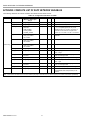
The following tables list all network variables associated with the ZAPP receiver.
Table A1. Configuration Variables for ZAPP.
NV Name
nciRmConfig
Field Name
Engineering Units: English
(Metric) or States plus
Range
Default
1
SH
2
Comments
HB
.low_setpt
SNVT_temp_p: 0..-5 Kelvin
-5
Low-temperature setpoint offset limit
.high_setpt
SNVT_temp_p: 0..+5 Kelvin
+5
High-temperature setpoint offset limit
.fanstages
enum 0..3
0 = NO FAN
1 = ONE_SPEED
2 = TWO_SPEED
3 = THREE_SPEED
THREE_SPEED
Number of possible fanspeeds: 0=no fan /
1..3 = 1..3 speeds (plus Auto, off). If this
variable is set to 0 (= no fan), the button on
handheld can be used as a simple on/off
switch. Up = on, down = off, ok = no function.
.bypass
Bit
0 = NOT_ALLOWED
1 = ALLOWED
ALLOWED
Bypass allowed to be commanded over
handheld.
.unocc
Bit
0 = NOT_ALLOWED
1 = ALLOWED
ALLOWED
Unoccupied allowed.
.occ
Bit
0 = NOT_ALLOWED
1 = ALLOWED
ALLOWED
Occupied allowed.
.sblnd_runtime
SNVT_time_sec: 1..240s
60
maximum movement time fur sunblinds
.lamp_runtime
SNVT_time_sec: 1..60s
10
Button 5 (bright): Maximum time for dimming
dark -> bright
.lamp_start
1=100%
0= last level
0
Button 5 (bright): Start dimming brightness at
100% or at last light level
.lamp_increment
SNVT_lev_percent: 0..100%
100
Button 5 (bright): Step height for dimming
.free_runtime
SNVT_time_sec: 1..60s
10
Button 6 (free): Maximum time for dimming
dark -> light
.free_start
1=100%
0= last level
0
Button 6 (free): Start dimming brightness at
100% or at last light level
.free_increment
SNVT_lev_percent: 0..100%
100
Button 6 (free): Step height for dimming
SNVT_time_sec
60
After this timeout, the ZAPP receiver sends
nvoSetptOffset and nvoSpaceTemp to the
network.
nciSndHrtBt
1
SH:
2
HBT: These points are either sent out on the network (outputs) or received from the network (inputs) at a certain fixed interval (heartbeat).
Sharable (bindable) points can be set up for data sharing either a data source or as a destination.
EN0B-0286GE51 R1101
12
ZAPP RECEIVER SYSTEM ENGINEERING
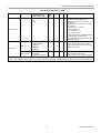
Table A2. Input Variables for ZAPP.
NV Name
Field Name
Engineering Units:
English (Metric) or
States plus Range
Digital
State /
Value
SNVT_Count
1..16
0, FFFF
Default
FFFFh
nviTeachActivate
1
SH
Comments
HB2
The number with this variable starts teachin process of ZAPP handheld, e.g.
nviTeachActivate = 2 starts teach of
handheld 2
nviTeachActive = 0 or FFFFh: no activity /
stop process
possible range:1..16, FFFFh
Device numbering is:
1..8 = handheld 1..8
9..16 = wall module 1..8
Visual (LCD) Behavior of ZAPP receiver
is equal to teach-in without tools
The result of teach-in can be read out of
nvoRfState.teached.
object_id
SNVT_obj_request
0 = NODE_OBJECT
1 = ROOM1
2 = ROOM2
..
8 = ROOM8
object_request
object_request_t
RQ_NORMAL
RQ_UPDATE_STATUS
nviRequest
This input variable belongs to the Node
Object and provides the mechanism to
request a particular mode for a particular
object within a node.
0
2
See above. Commanding any modes other
the ones listed will result in an
“invalid_request” when reading nvoStatus.
1
SH:
2
HBT: These points are either sent out on the network (outputs) or received from the network (inputs) at a certain fixed interval (heartbeat).
Sharable (bindable) points can be set up for data sharing either a data source or as a destination.
13
EN0B-0286GE51 R1101
ZAPP RECEIVER SYSTEM ENGINEERING
The fixed values of the variables are described in the ZAPP Handheld User Manual (EN2B-0205GE51 R1100).
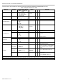
Table A3. Output Variables for ZAPP.
NV Name
Field Name
Engineering Units: English
(Metric) or States plus
Range
Default
1
SH
2
Comments
HB
User occupancy override.
nvoOccManCmd*
SNVT_occupancy
0 = OC_OCCUPIED
1 = OC_UNOCCUPIED
2 = OC_BYPASS
0xFF = no
override
X
nvoSetPtOffset*
SNVT_temp_p:
-5..+5 K due to nciRmConfig
0
x
.value
SNVT_switch.value: 0..100%
O%
x
.state
SNVT_switch.state:
0 = OFF
1 = ON
255 = NUL
NUL
x
SNVT_setting
3 = SET_UP
2 = SET_DOWN
4 = SET_STOP
255 = SET_NUL
SET_NUL=
no action
x
Allows user to command sunblinds.
SNVT_switch.value: 0..100%
0
x
Allows user to switch a light on/off or
to dim it.
SNVT_switch.state:
0 = OFF
1 = ON
255 = NUL
NUL
x
Allows user to switch a light on/off or
to dim it.
.value
SNVT_switch.value: 0..100%
0
x
Same as above.
.state
SNVT_switch.state:
0 = OFF
1 = ON
255 = NUL
NUL
x
Same as above.
SNVT_temp_p 0..40° C
invalid
x
.BatteryState1
...
.BatteryState16
Bit:
0 = battery ok
1 = battery low
0 = ok
Battery condition for handheld in
room 1..8 (=state 1..8) and optionally
from receiver in room 1..8 (=state
9..16)
.teached1
...
.teached16
Bit:
1 = taught
0 = no device taught
0, but saves
value over
power down
1..8 = handheld in room 1..8
9..16 = wall module in room 1..8
.lastRfDevice
Byte:
0..16
nvoFanSpeedCmd*
nvoSblndManPos*
nvoLampManPos*
nvoFreeUse*
nvoSpaceTemp*
nvoRfState
1
SH:
x
User setpoint temperature offset.
Manual user override of fanspeed.
x
Shows wall module temperature of
taught ZAPP receiver.
Where did the last ZAPP message
come from?
1..8 = handheld in room 1..8
9..16 = receiver in room 1..8
Sharable (bindable) points can be set up for data sharing either a data source or as a destination.
2
HBT: These points are either sent out on the network (outputs) or received from the network (inputs) at a certain fixed interval (heartbeat).
*Each of these variables exists for room1 to 8 with a single-digit index 1..8.
EN0B-0286GE51 R1101
14
ZAPP RECEIVER SYSTEM ENGINEERING
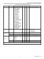
Table A3 (continued). Output Variables for ZAPP.
NV Name
nvoRfState
Field Name
.lastCommand
Engineering Units: English
(Metric) or States plus Range
Default
1
SH
2
Comments
HB
Shows last ZAPP message received.
Enum:
0 = OFFS_HIGHER
1 = OFFS_LOWER
2 = OFFS_ZERO
3 = OFFS_MIN
4 = OFFS_MAX
5 = FAN_HIGHER
6 = FAN_LOWER
7 = FAN_AUTO
8 = FAN_MAX
9 = FAN_OFF
10 = OCC_BYP
11 = OCC_UNOCC
12 = OCC_NUL
13 = OCC_OCC
14 = LIGHT_MAX
15 = LIGHT_MIN
16 = LIGHT_START_DIM
17 = LIGHT_STOP_DIM
18 = SBL_UP
19 = SBL_DOWN
20 = SBL_STOP
21 = OFFICE_STYLE_1
22 = OFFICE_STYLE_2
23 = FREE_MAX
24 = FREE_MIN
25 = FREE_START_DIM
26 = FREE_STOP_DIM
27 = DIRECT_SETPT
28 = ROOM_TEMP
255 = CMD_NUL
nvoRfState
.TeachActive
Shows the ZAPP device number currently
in the teach-in mode.
0 = no teach-in process.
1..8 = handheld in room 1..8. 9..16 =
receiver in room 1..8
Current software version of LONW ORKS
chip
SNVT_count: 0..16
.major
nroSwVersion
.minor
.bug
.object_id
0 = NODE_OBJECT
1 = ROOM1
2 = ROOM2
3 = ROOM3
...
8 = ROOM8
.invalid_id
0 = VALID_ID, 1 = INVALID_ID
.disabled
0 = ENABLED, 1 = DISABLED
nvoStatus
1
SH:
2
HBT: These points are either sent out on the network (outputs) or received from the network (inputs) at a certain fixed interval (heartbeat).
Sharable (bindable) points can be set up for data sharing either a data source or as a destination.
15
EN0B-0286GE51 R1101
ZAPP RECEIVER SYSTEM ENGINEERING
Home and Building Control
Honeywell Inc.
Honeywell Plaza
P.O. Box 524
Minneapolis, MN 55408-0524
USA
http://www.honeywell.com
EN0B-0286GE51 R1101
Home and Building Control
Honeywell Limited-Honeywell Limitee
155 Gordon Baker Road
North York, Ontario
M2H 3N7
Canada
http://www.honeywell.ca
Home and Building Control
Honeywell AG
Böblinger Straβe 17
manufacturing location
D-71101 Schönaich
certified to
Germany
http://europe.hbc.honeywell.com
printed in Germany
Subject to change without notice