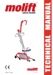
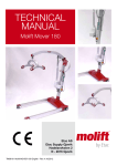
Download Molift Quick Raiser 2 Technical Manual (New)
Transcript
TM04201 Molift Quick Raiser 2 09 English
TECHNICAL MANUAL
-a patient lifter from
Contents
General advice. ...................................................... 3
Explanation of symbols................................... 3
Safety regulations............................................ 3
Liability............................................................... 3
Technical description.......................................... 4
Chassis.............................................................. 4
Motor with mounting plate and coupling ....... 4
Motor control ................................................. 4
Motor/actuator for leg spreading.................... 4
Hand control................................................... 4
Emergency stop............................................. 4
Battery indicator............................................. 4
Wheels........................................................... 4
Lifting column.................................................... 5
Battery holder and batteries .......................... 5
Operating handle............................................ 5
Manual control................................................ 5
Service....................................................................... 6
Notice of Service.............................................. 6
Service .......................................................... 6
Cleaning. ........................................................... 6
Troubleshooting................................................ 6
Replacement of parts ......................................... 7
Equipment and special tools. ......................... 7
Equipment......................................................... 7
Special tools. .................................................... 7
Lifting motor, removing.................................... 7
Lifting motor, fitting........................................... 7
Replacing the motor for the leg-spreading
mechanism........................................................ 7
Wheels, removing and fitting.......................... 8
Wheels on the spreading legs........................ 8
Ø100mm wheels............................................ 8
Ø115mm wheels............................................ 8
Replacing the electronics................................ 8
Replacing the contact points in the lifting
column .............................................................. 9
Replacing the contact points in the chassis. 9
Replacing the column wiper-brushes............ 9
Faults in the lifting column.............................. 9
Inspection Diagram after Service and
Repair........................................................................11
Service:.............................................................11
Safety Inspection.............................................11
Parts list.................................................................. 12
Molift Quick Raiser 2. .................................... 12
Main Components.......................................... 13
Appendix B............................................................ 14
Chassis / Spreading mechanism for legs... 15
Appendix C............................................................ 16
Lifting column...................................................17
Appendix D............................................................ 18
Leg. .................................................................. 19
Appendix E. ........................................................... 20
Cover with electronics QR2.......................... 21
Battery holder. ................................................ 21
Appendix F............................................................. 22
Knee support complete................................. 22
Electrical Diagram.......................................... 23
IMPORTANT!
The patient lifter is only meant to be used by
qualified personnel.
The manual shall not be handed over, or made
available to, any unauthorised third party, without a prior written consent from Molift Group
AS. Existing laws, conventions and agreements
protects all documents. No extract of this documentation can be reproduced, used or transferred without prior written consent from Molift
Group AS. Violation of these regulations may
lead to judicial repercussions and economic
responsibility. Industrial rights are reserved.
Completing the job............................................. 10
Safety checks. ................................................ 10
Keeping a log.................................................. 10
Page 2 of 24
TM04201Molift
Molift Quick
RaiserAS
2 09 English- Rev C - 01/2011
Group
Ole Deviksvei 44
0668 OSLO, Norway
General advice
This technical manual contains important information about the lifter, including safety instructions.
It is therefore essential to read it carefully before
using and repairing the patient lifter.
Explanation of symbols
Locations in diagrams are referred as follows:
A 1 A1 refers to Appendix A, location 1.
This symbol appears in the user manual next
to all the information which concerns safety
in the work-place and the risk of injury. Always
follow these instructions carefully, paying due
attention and caution.
This symbol indicates important information
regarding the correct use of the equipment
as described in this technical manual. If this
information
IMPORTANT! is not taken into account, malfunction or damage to the equipment may
result. lifter is only meant to be used by
The patient
qualified personnel.
This symbol draws your attention to especially useful
information,
which
could
help the
The manual
shall
not be handed
over,
or made
user to,
of any
this unauthorised
equipment tothird
workparty,
morewitefficiavailable
information
proceduhout ently.
a priorThis
written
consentmay
fromsimplify
Molift Group
res
or
clarify
complications.
AS. Existing laws, conventions and agreements
protects all documents. No extract of this doSafety
regulations
cumentation
can be reproduced, used or transHeavy,
long
and/or
objects
will
have
to be
ferred without
priorsharp
written
consent
from
Molift
lifted
andAS.
handled
when
repairing
the lifter.may
When
Group
Violation
of these
regulations
assembling
and
removing
parts,
the
lifter’s
stabilead to judicial repercussions and economic
lity
may be affected
with rights
the risk
it overturning
responsibility.
Industrial
areofreserved.
or falling over.
Liability
Please read these instructions carefully before
putting the product into operation, service or
repair. We assume no liability for damage or malfunctions resulting from failure to comply with
the instructions. Warranty claims must be made
immediately on detecting the defect. Remember
to quote the serial number. Consumable parts are
not subject to the warranty.
All technical information, data and instructions
for operation, servicing and repair contained in
these instructions were up-to-date at time of print
and are compiled on the basis of our experience
and to the best of our knowledge. We reserve the
right to incorporate technical modifications within
the scope of further development of the product
described in this manual. No claims can be derived
from the information, illustrations or descriptions
contained in these instructions. We assume no
liability for any damage or malfunction caused
by operating errors, non-compliance with these
operating and repair instructions or inappropriate maintenance. We expressly point out that only
genuine Molift Group AS spare parts and accessories approved by us may be used. For safety
reasons, the fitting and use of spare parts or accessories, which have not been approved, and unauthorised modification or conversion of the product,
are not permitted. Molift Group AS will accept no
liability for damages resulting from such acts.
With the exclusion of product liability, Molift Group
AS is liable for faults or omissions on its part within
the scope of the warranty obligations stated in the
purchase contract. Claims for damages are excluded, irrespective of the legal reason from which
You are therefore advised to be attentive and such claims are derived. Only documentation
belonging to the actual equipment is valid.
careful!
Any failure to comply with the safety regulations
and precautionary measures stated in these operating instructions renders the declaration of conformity supplied with the system in accordance
with Council Directive (93/42/EEC) concerning
medical devices invalid.
Molift Group AS
Ole Deviksvei 44
0668 OSLO, Norway
Teleph:(+47) 40001004
Fax: (+47) 40001008
www.molift.com
[email protected]
Page 3 of 24
Technical description
Hand control
The contact switch for manual control is of the DIN
type with special cables. This is located inside one
Chassis
The chassis consists of a steel-tube and steel-plate of the side housings.
frame with a polyester seal. The side housings are
constructed in vacuum-moulded ABS. The spread- Emergency stop
ing legs are made of aluminium sections with The emergency stop, which is located on the top
castors incorporating injection-moulded plastic of one of the side housings, cuts the power supply
wheel brackets.
to the motor. The button is pushed straight down
to activate the emergency stop and is released by
twisting.
The chassis consists of:
•
•
•
•
•
•
•
•
•
•
Motor with mounting plate and coupling
Motor control card (PCB) for lifting
Motor/actuator for leg spreading
Motor control for leg spreading
Contacts for battery power
Contact switch for manual control
Emergency stop
Charging indicator
Wheels
Side housings
Do not activate the emergency stop with your
foot. This could damage the emergency stop
switch!
Battery indicator
A light-emitting diode is fitted in one of the side
housings. This lights up when the battery voltage
drops below 12.2 volts. The diode will normally
flash when starting or stopping. If the diode lights
up when the lifter is being operated, the battery
needs charging. But there will still be sufficient
Motor with mounting plate and coupling
remaining battery capacity for 1-3 normal lifts of
Motor with worm gear (12 V DC) mounted inside 75 kg and there will always be sufficient remaining
the chassis. The coupling between the motor and current for lowering the patient.
column is engaged when the red arrow on the
lower part of the column is in line with the upper Wheels
part of the chassis. The motor must not be lubrica- The lifter has three types of wheel. None requires
ted after leaving the factory.
lubrication:
Motor control
The motor control (electronic) has integral overload protection, which will cut off the current in
the event of overloading. The current is cut off
when the overload corresponds to approximately
17A above and 7A below. The motor therefore
stops automatically when the load exceeds 160 kg.
Castors on the spreading legs
The castors on the spreading legs are mounted
in injection-moulded plastic brackets which are
firmly riveted to the spreading legs.
Back wheels
One wheel on each side, diameter 115mm. These
wheels are fitted to the chassis with stud screws.
They can be locked by a push-button.
There is also the same type of integral current
limiter in the leg-spreading motor, designed to
reduce the danger of overloading the motor and Support wheels
to reduce the risk of pinching.
One central wheel on each side of the lifter, diameter 100mm. These wheels are fitted to the chassis
Motor/actuator for leg spreading
with straight-through screws.
An actuator is fitted inside the chassis which drives
the leg-spreading mechanism via two bars.
Page 4 of 24
TM04201 Molift Quick Raiser 2 09 English- Rev C - 01/2011
Lifting column
The lifting column consists of:
•
•
•
•
•
•
•
•
•
•
Aluminium section
Column brushes
Linear ball screw
Ball nut (with integral ball bearings)
Runner-block with wheel
Bearing race
Motor coupling
Contact for battery current
Aluminium battery holder
Fastening knob with lock-screw
Operating handle
The height of the operating handle (which consists of a curved steel tube) can be adjusted by
means of a special bolt and knob so as to suit different users.
Manual control
The manual control has four buttons. There are ‘up’
and ‘down’ buttons for the lifting operation, and
two buttons for moving the spreading legs outwards and inwards.
When the lifter is operated in wet areas, make sure
that the O-ring in hand control contact is in place.
The motor transfers power to the ball screw via
the motor coupling. A ball nut runs along the ball
screw. The runner-block is attached to this ball nut.
When the motor turns the ball screw via the coupling, the ball screw moves the ball nut plus runner-block upwards or downwards. There are tracks
in the aluminium section for the runner-block’s
wheel to follow. The ball screw is factory-lubricated and requires no further lubrication. It is protected from dirt by two column wiper-brushes.
Battery holder and batteries
The battery pack is placed in a special aluminium holder on the lifting column. See also the
instructions for the charger. Only use original
Molift Batteries for Molift lifters.
Page 5 of 24
Service
All repair and service must be logged for each
lift. After service and/or repair, the lift should be
checked using the Inspection diagram on page 13.
Molift Quick Raiser is a mobile lift, which needs
relatively little maintenance and has few parts.
Take good care of your Molift Quick Raiser and The lift owner is responsible for storing the inforfollow the regular service regulations, and you will mation on inspections, service and repair.
enjoy using it for many years. Service must only be
Cleaning
done by authorised personnel.
In addition to the required service, Molift recommends regular inspections to detect unforeseen damages and faults. A checklist for periodic
inspections is found in the User Manual.
Notice of Service
The lifter has a built-in service light, which gives
a warning when service is needed. The light is
green when the lift can be used in a normal way.
The electronics registers the loads and how much
the lift is used, and after a certain operation time
a signal warns that service is needed. The light
will be yellow at first, then red. The lift may still
be used, but you should order a service from your
local service partner. An additional buzzer indicates when the lift needs service urgently.
Detergents used should be pH-neutral. Do not
use solvents or other strong fluids, which may
damage or ruin outside surfaces or change
the characteristics of lift materials. If disinfection is necessary, use isopropyl alcohol. Avoid
using abrasives and corrosives.
Wash the outside with a damp cloth and a suitable
detergent.
Troubleshooting
If the lift is not functioning, the first action is to
check that the power supply is in order. Then check
that the battery light is on and that the service
light is not indicating a need for service. See the
troubleshooting table in the user manual.
Should the troubleshooting table not yield a fault
diagnosis, use your judgment and a process of elimination.
Only use spare parts from Molift Group AS.
It will be up to the repair engineer to make such
assessments, so there is no need to describe any
further fault-finding procedures.
Service lamp
Use the Molift Servicetool and read the lift data
and number of lifts. The Molift Servicetool is also
used for resetting the service light after service.
Service
Service should be done when the service light
signals or at least after five years. Service includes control and replacment of worn and damaged
parts.
If you have any further questions on service and
maintenance, please contact Molift Group AS.
Page 6 of 24
TM04201 Molift Quick Raiser 2 09 English- Rev C - 01/2011
Replacement of parts
Equipment and special tools
• The newly-fitted motor should be labelled with
the date of fitting and the fitter’s signature.
• Replace the side housings.
Replacing the motor for the leg-spreading
Equipment
See the Operator Manual for accessories and mechanism
equipment relating to the daily use of the lifter.
You will need:
• Hex key 5mm
• Long-nosed pliers
Special tools
No special tools are required.
Procedure:
• Remove the lifting column
The replacement of parts must only be carried • Remove the motor housings B 8 and B 20 (ABS
out by authorised dealers!
housings)
• Disconnect the electric cables from the motor
B6
Lifting motor, removing
You will need:
• Hex key 5mm
Procedure:
• Remove the lifting column
• Remove the motor housings B 8 and
B 20 (ABS housings)
• Unscrew the three hexagonal screws B 19 at the
foot of the column which attach the motor to
the chassis.
• Disconnect the electric cables from the motor
• Pull the motor downwards then out from the
chassis
Lifting motor, fitting
You will need:
Observe how the wires are connected to the
motor. If necessary, make notes and/or mark
the wires to ensure that the new motor is
wired correctly.
• Remove the pins from the bolts B 24 in front of
and behind the motor and pull out the bolts
• Lift out the motor
• Position the new motor and insert the bolts
and then the pins
• Connect the cables to the motor
• Check that the lifter functions correctly
• Replace the motor housings and reposition the
lifting column
• Hex key 5mm
• Loctite 243
Procedure:
• Follow the above procedure in the reverse
sequence. Put Loctite 243 on the motor’s three
mounting screws before assembling, but only
screw them in slightly. Check that the three
rubber washers for these three screws are properly seated. Before fixing the motor in place,
it should be centred in relation to the lifting
column place the column in its correct position
on the chassis to check this.
• Engage the lifting column and operate the
motor until the runner-block on the ball screw
comes all the way down and the motor stops.
Only then should you tighten up the motor’s
mounting screws.
Page 7 of 24
Wheels, removing and fitting
Procedure:
Wheels on the spreading legs
The entire bracket plus castor wheel has to be
replaced.
It will be necessary to heat the screw/bolt to
loosen the Loctite applied during assembly.
Be careful when heating the screws. Use a
nozzle on the hot air gun so as to limit the
heated area if possible.
You will need:
• Pop rivets 4.8 x 16mm, plus tool
• Drill Ø 5mm
Procedure:
• Carefully drill out the pop rivets underneath the
legs so as to release the wheel bracket. D 2
Use a 19mm spanner to remove the front wheel
B 5 . Unscrew the wheel screw B 12 and remove
the wheel. Fit the new wheel with screw and 19mm
spanner. Use Loctite 2701 to secure the screw.
Be careful not to damage the lifter when drilling out the pop rivets.
Replacing the electronics
• Pull out the wheel bracket D 2 from the leg.
• Position the new wheel bracket and check that
the holes in the leg line up with the holes in the
wheel bracket.
• Attach the wheel bracket with the pop rivets.
• Press the wheel into place if necessary.
Ø100mm wheels
You will need:
• Hex key, 5mm
• Loctite 2701
• Hot air gun
Procedure:
It will be necessary to heat the screw/bolt to
loosen the Loctite applied during assembly.
It will be necessary to copy settings from the
old PCB in the lifter over to the new PCB before
replacing by using the Molift Service Tool.
NOTE! IF INFORMATION ON PCB IS LOST OR
INCORRECT THE SETTINGS SHOULD NOT BE
COPIED. In this case a programmed card must
be ordered and placed in the lifter without
copy settings.
Correct settings for Molift Quick Raiser when
reading Product Info with Molift Service Tool are:
• ”Product” - a 4 digit number (1802=Molift
Quick Raiser 2).
• ”Software version” - a 2-digit number
• Production year, week, batch number, serial
number and maximum load should be according to main label.
Be careful when heating the screws. Use a
nozzle on the hot air gun so as to limit the You will need:
heated area if possible.
• Hex key, 5 mm
4
Remove the wheel B by unscrewing the 8x50 Procedure:
screw B 14 with the Umbraco key. Fit the new • Loosen the cover with electronics B 20
wheel by following these procedures in reverse. • Observe how all the wires are connected – if
Remember to fit the washer when assembling. Use
necessary mark the cables or make a drawing.
Loctite 2701 to secure the screws.
• Remove the 4 plastic rivets B 9 and remove the
PCB cover.
Ø115mm wheels
• Detach the printed circuit board from the slot
in the side cover.
You will need:
• Disconnect all the wires from the Main PCB, and
• 19mm spanner
connect to the new Main PCB. Move all exten• Loctite 2701
sions and caps to the new Main PCB.
• Hot air gun
Page 8 of 24
TM04201 Molift Quick Raiser 2 09 English- Rev C - 01/2011
Check the polarities: the red wire is connected
to the + sign on the contact-holder
• Carefully position the new contact-holder and
attach it with the posidrive screw
Replacing the contact points in the chassis
You will need:
• Place the new Main PCB in the slot in cover.
• Ordinary screwdriver for slotted screw-heads
• 5.5mm spanner
Procedure:
• Put extension cable B 13 through the hole with
cable gland and connect to the Main PCB.
• Loosen the contact-points holder B 26 in
the foot of the column on the chassis by
unscrewing the two screws B 29 holding the
unit.
• Pull it out carefully so that you will be able to
disconnect the wires with the soldering iron
• Disconnect the old holder with the soldering
iron and solder the wires on to the new unit.
Check the polarities: the red wire is connected
to the + sign on the contact-holder
• Position the holder in the foot of the column
and screw it in.
Replacing the column wiper-brushes
You will need:
• Posidrive screwdriver
• Check that the LED lamps are positioned correctly when assembling the PCB cover to the
side cover. Attach with 4 plastic rivets.
• Check that the lifter functions correctly
Procedure:
• Loosen the housing on the top of the column
by unscrewing the four screws
• The wiper-brush strips can now be reached and
pulled out
• Insert the new wiper-brushes and screw on the
housing
Replacing the contact points in the lifting
column
Faults in the lifting column
You will need:
If any mechanical faults or misalignments occur
• Posidrive screwdriver
in the lifting column and/or runner-block/lifting• Soldering iron
arm, no attempt must be made to repair them.
Procedure:
• Loosen the posidrive screw in the groove at the Structural damage to these parts can impair the
lifting strength, and therefore the parts must be
bottom of the column so that the contact-hol8
returned to the manufacturer for assessment and
der C is released
repair as necessary. Contact Molift Group AS.
• Pull out the holder carefully so that the wires
are freed (about 5 cm)
• Use the soldering iron to disconnect the contact-holder and solder the wires to the new unit
Page 9 of 24
Completing the job
Keeping a log
Below there is a table for logging any repair work
including the repair of any damage. Give a brief
Safety checks
A safety check should be carried out after any type description of the work carried out so that it is
of repair or replacement. This check is to be perfor- possible to see what has been done over a period
med according to the checklist on next page. The of time. Later on this could help service engineers
owner of the lifter shoul keep one filled out and when fault-finding, and therefore make any subsequent work more efficient.
signed checklist after each repair or service.
Date
Description of fault
Page 10 of 24
Description of repair
Date/sign.
TM04201 Molift Quick Raiser 2 09 English- Rev C - 01/2011
Inspection Diagram after Service and Repair
MOLIFT Quick Raiser 2
Service:
Checked service lamp if service is necessary: YES (yellow or red light) / NO (green light)
Use Molift Servicetool and read the lifters data - check number of lifts left before service: _____________________
Service is completed : - Worn or damaged parts, or malfunctioning parts, are replaced. See description for parts
replacement.
Service light was reset using Molift Servicetool. N.B.: The service light must ONLY be reset after completed service!
Perform safety inspection after service.
Safety Inspection
The lift has been visually checked for damages, malfunction and deformation, and it is in order. Checked that lifting
column is properly fastened to chassis, and lifting arm to lifting column and that the lifter has no loose parts.
Checked that remote control works and that wire and socket for remote control are undamaged.
Moved the lift around a level and even floor with approx. 75 kg hanging in the suspension about 60 cm above the
floor. The lifter moves in all directions in a stable manner without tipping or experiencing any instability.
Run the lifter up and down several times with a test load, (QR2:120 kg and QR2+: 150 kg), on a level floor: Attach the
special designed test hoop to the lifters knee support bracket, and hook the rope on to the Raiser arm. The weights,
(i.e. sandbags or steel weights), are then hooked on to the test hoop by using strong ropes. See to that the weights
do not touch the column or chassis during the test. After the test inspect the chassis, wheels, column, carrier and
Raiser arm again for damage or deformation. If necessary, replace the damaged parts and do the test again until the
lifter is functioning correctly.
Test with test jig - Run the lift up and down 2 - 3 times with maximum load. Perform a new visual control; damage,
play and deformations as described above. Any damaged parts must be repaired or replaced and the test is performed once more until the lift performs correctly.
Checked that the leg spreading mechanism functions properly. Tested with maximum load. Verified that the legs do
not move beyond inner and outer limits (working position) when operated with load.
Checked that emergency stop and lowering (electric and manual) are working correctly.
Service light is green and batteries are sufficiently charged.
Marked lift with safety sticker with month/year and certificate number for completed safety inspection. Inspecting
person must sign safety sticker and this diagram.
Inspection, repair and service should be done by a person certified by, or on behalf of Molift Group AS.
Always complete below:
Client:________________________________ Serial number of lifter:_______________________________
Date: ________________________________ Signature:_________________________________________
Page 11 of 24
Parts list
Pos.
Qty
Art.no.
Description
Molift Quick Raiser 2
Pos.
Qty
Art.no.
Description
1
0421200
Chassis, see App A
2
0412014
Column
3
0458010
Lifting Arm U-shape
0458107
Lifting Arm V-shape (optional)
4
042500
Drive Handle
5
0455000
Knee support w/small cushions
0455001
Knee support w/large cushions (optional)
Page 12 of 24
TM04201 Molift Quick Raiser 2 09 English- Rev C - 01/2011
Main Components
3
4
2
5
1
Appendix A
Page 13 of 24
Appendix B
Pos.
Pos.
Qty
Art.no.
Description
1
1
0421003
Chassis welded QR2
2
2
0421106
QR2, Leg assy
3
2
0920206
Screw DIN 912 M8x60 Elzn
4
2
0420102
Wheel 100mm QR1/QR2/QR2+
5
2
0220208
Wheel w brake Ø115mm
6
1
0421110
Motor 12 V linak LA2 leg spreading mech
7
2
0421111
Bolt for leg, QR2
8
1
0421115
Cover left QR2
9
4
0420104
Nut for cover M6
10
1
0421129
Foot Rest Right Assy
11
1
0421128
Foot Rest Left Assy
12
2
0235104
Setscrew DIN 916 M10x30 Elzn
13
2
0310114
Washer DIN 433 Ø8,4 Elzn
14
2
0420106
Screw ISO 7380 M8x50 10.9 UB
15
1
0220110
Motor Complete
16
1
0220111
Motor connector male
17
3
0220118
Washer Neoprene Ø22x5,5x3,5
18
3
0220121
Washer DIN 9021 Ø6,4 Elzn
19
3
0220120
Screw DIN 912 M6x20 8.8 Elzn
20
1
0421127
Cover w electronics
21
1
0421501
Legs rod assembly
22
2
0421108
Spacer Ø8,4xØ12x20
23
2
0421109
Spacer Ø8,4xØ12x25
24
2
3500211
Clewis Pin Headed HCB Ø10x35x3
25
2
3500218
Split pin DIN94 Ø2,5x16
26
1
0421133
Connection Point QR
27
1
1150129
Spacer Nylon 13ME103
28
1
0220129
Set screw DIN 916 M5x10
29
2
0420118
Screw DIN 912 M3x16 Elzn
30
2
0420117
Nut, Lock DIN 985 M3 Elzn
31
2
0220122
Washer DIN 125B Ø10,5 Elzn
32
2
0420251
Anti Skid Label QR
33
1
0421134
Main Label QR2
34
1
0421135
Decal: ID number
35
4
0421114
Circlip Ø20mm Elzn
36
2
0421140
Top sealing SY33.360 5 cm
37
4
0490205
Support Partner/QR (130x80x348)
39
1
2018004
Hand Control Partner
41
1
0421142
Cable Clip Male 6,3x0,8x1,5 Insulated
42
1
0421143
Cable Clip Female 6,3x0,8x1,5 Insulated
43
1
1101432
Cable clamp 4,8mm 55-021-90
44
1
0420120
Screw DIN 7981F 4,8x9,5 Elzn
45
1
0220310
Label Safety Check
46
1
0620133
Cable clip 4,8 selfadhesive
47
2
0220136
Strip 100x2,5mm nature
48
1
0440003
O-ring 10x2 SKG
49
1
0228120
Bearing Ø10
Page 14 of 24
Qty
Art.no.
Description
TM04201 Molift Quick Raiser 2 09 English- Rev C - 01/2011
Chassis / Spreading mechanism for legs
Add o- ring on hand set
before assembly. (Pos 48))
45
10
20
9
9
8
29
26
9
34
33
9
32
43
11
1
4
5 millimtre
ce. If the wheel
eels need to be
13
LOCTITE 2701 14
Cable on actuator
6
to be cut 100 millimetre long
Assemble cable clip.
24
Blue = male
Brown = female
23
32
30
16
19
22
Replace bearings
3
49
F
17
28
24
27
21
18
15
2
14
13
LOCTITE 2701
4
31
12
LOCTITE 2701
25
3
22
23
2
25
7
36
35
35
7
35
5
E
31
12
LOCTITE 2701
5
37
38
39
C
D
40
41
E
42
Assembly and programming instru
Electrical scheme = 08-194
1
Pos.
Bill of materials:
Designed/Drawn: Date:
F
Appendix B
Added pos 48 and 49, EO33-10
08.03.2010
MHL
TÅB
E
Uppdate of pos no
23.03.2009 TÅB
MHL
Drawing name:
D
Uppdate of drawing
11.02.2009 TÅB
MHL
C
Added pos 39
29.01.2009/TES
MHL
B
Uppdate of list
21.01.2009 TÅB
MHL
A
Rev.
Released for production
Description:
10.09.2008 TÅB
Date/Sign.
MHL
Approved:
08-071 BOM.xls
Dimension/
Draw. no.
Qty. Description.
Projection:
01/09-2008
Scale:
1:5
Chassis complete QR 2
Molift Quick Raiser
Page 15 of 24
Appendix C
Pos.
Qty
Art.no.
Pos.
Qty
Art.no.
Description
Description
LIFTING COLUMN
1
1
0412011
Ball screw assy
2
1
0210116
Top cover
3
1
0411101
Profile column
4
1
0410106
Distancer
5
2
0411104
Column brush 0.7,0.10 Nylon 1200
6
4
0710530
Screw Pan head cross ISO 7045 M5x16
7
1
0510500
Battery Holder complete 14,4 V
8
1
0510520
Connection point
9
1
0210302
Red label right
10
1
0210301
Red label left
11
1
0210305
Label sling
12
1
1310303
Label emergency lowering
13
1
0410308
Label Quick Raiser
14
1
0420310
Label scale 1-30
15
1
0210304
Label red arrow
16
1
1310306
Label Art. no. / batch no.
17
1
1310307
Label controlled/sign
18
1
0410117
Cable gland RG2
19
1
0410118
Cable gland
20
1
0420150
Bracket
21
1
0220102
Screw DIN 912 M10x14
22
1
0410306
Rubber Bunpron Grey
23
1
0235107
Bolt for handle / nee pillow holder
24
1
0235102
Hand wheel
25
1
0210307
Label emergency lowering
26
1
0220151
Screw DIN 7981C Ø3,5x6,5 Elzn
27
1
0220150
Screw DIN 965A M3x8 Elzn
28
1
0210124
Allen Key 4 mm
29
1
0220127
Allen Key 8 mm
042500
DRIVE HANDLE
1
Handle, use 042500
2
Grip, use 042500
3
0235102
Adjusting Wheel M10/ø50
4
0235107
Connection Bolt, Push Bar
Page 16 of 24
TM04201 Molift Quick Raiser 2 09 English- Rev C - 01/2011
Lifting column
25
C
45
235
1210
4
6
2
28
29
1
184
6
6
6
7
5
30
29
28
10
B
27
26
30
25
26
24
3
22
20
21
21
22
14
24
23
5
23
22
21
20
17
16
15
14
13
9
12
13
27
12
11
10
9
Assembly instructions / labeling = 08-P004
Note! all labeling to be done according to instruction 08-P04
11
1
Pos.
Bill of materials:
08-091 BOM.xls
Dimension/
Draw. no.
Qty. Description.
Material.
8
Comment.
7
8
6
17
Designed/Drawn: Date:
Note!
Solder cables from battery baox according to
assembly instructions 08-P04
(Red to + and black to - marked in the plastic)
16
TÅB
Drawing name:
C
B
A
Rev.
15
11.05.2009 TÅB
23.03.2009 TÅB
27.09.2007 TÅB
Date/Sign.
MHL
MHL
MHL
Approved:
Projection:
27/09-2007
Scale:
5
4
3
31
1
1:5
Coloumn assy
Drawing number:
08-091
Molift Quick Raiser
Size
A2
Pos.
167
Drive handle
Made separate assy of top plate
Added pos 30 User manual
Released for production
Description:
Glued with
BOSTIK 3665
2
565
4
2
Gluded with
BOSTIK 3665
Assembly instructions = 08-P13
1
Pos.
Bill of materials:
Qty. Description.
08-172 BOM.xls
Dimension/
Draw. no.
Material.
Comment.
3
Designed/Drawn: Date:
1
TÅB
Drawing name:
Projection:
29/09-2007
Handle complete
A
Rev.
Released for production
Description:
28.09.2007 TÅB
Date/Sign.
MHL
Approved:
Scale:
1:5
Molift Quick Raiser 2008
08-172
Drawing number:
Size
A3
Pos.
Appendix C
4
1
3
2
1
1
2
1
Qty.
Bolt M10
Hand wheel ø50
M10
Grip handle
Description
Page 17 of 24
0235107
0235102
458101
02-133
Dimension
Draw. no.
Appendix D
Pos.
Pos.
Qty
Art.no.
Description
1
1
0421101
Leg profile
2
1
0420505
Wheel bracket, incl pos 4, 5, 6, 7
0910180
Flanged bushing
3
2
4
1
Wheel (inkl in pos 2)
5
1
Special nut M10 (inkl in pos 2)
6
2
Dowel rivet (inkl in pos 2)
7
2
Washer, fender (inkl in pos 2)
Page 18 of 24
Qty
Art.no.
Description
TM04201 Molift Quick Raiser 2 09 English- Rev C - 01/2011
94
Leg
3
1
5
828
2
B
3
7
B
7
6
4
1
Apply LOCTITE 2701
Pos.
Bill of materials:
Qty. Description.
Designed/Drawn: Date:
TÅB
Drawing name:
B
Changed pos 7 See EO
28.05.2010 TÅB
MHL
A
Rev.
Released for production
Description:
25.09.2007 TÅB
Date/Sign.
MHL
Approved:
Appendix D
08-085 BOM.xls
Dimension/
Draw. no.
Projection:
25/09-2007
Leg assy
Molift Quick Raiser 2
Page 19 of 24
Scale:
1:
Appendix E
Pos.
Qty
Art.no.
Description
1
0421118
Cover right QR2 09
Fig 1
1
Pos.
Art.no.
Description
COVER WITH ELECTRONICS QR2
2
1
1320112
Main PCB (Control card)
3
1
0920114
Emergency Stop Switch
4
2
1310135
Extension Cap 10 mm
5
1
1310136
End Cap
6
2
0421137
LED Guide
7
1
0421119
Cover PCB
8
6
0421120
Plastic rivet 5x4-7 Black
1
0220307
Label Emergency Stop
9
10
Qty
Screw - part of 0421120
11
1
0421121
Label service-em. lowering
12
1
0421122
Extension Emergency Stop Switch
13
1
0421123
Cable extension 13-pin DIN
14
1
0421124
Battery cable
15
1
0421125
Cable Motor 1
16
1
0421126
Cable Motor 2
17
2
0620134
Self-Adhesive Clamp 9,6
18
1
0410306
Bumpon Type SJ-5027 Grey
19
2
0420593
Panel holder for diode Ø5mm
20
1
0421138
Bushing GFW-1517-17
21
1
0421139
Tape TESA
Fig 2
BATTERY HOLDER
1
1
0510101
Profile/holder
2
6
0540501
Screw Wallboard Elzn
3
1
0510205
Lower part plastic
4
1
0510510
Upper cover mounted
5
6
7
8
1
0540505
Rubber bushing
9
2
0540120
Screw DIN965A Elzn
10
2
0540123
Nut w threads brass
11
1
0510302
Decal
12
1
Wire red 0,75 L=750
13
1
Wire black 0,75 L=750
14
1
15
1
Heat crimp tube
1310306
Page 20 of 24
Decal art.no
TM04201 Molift Quick Raiser 2 09 English- Rev C - 01/2011
Cover with electronics QR2
Fig 1
Glue pos 4 onto switch with
one drip quick glue.
13
3
8
15
9
4
21
4
22
7
17
C
12
5
9
10
8
17
20
11
18
16
1
19
Mount in front wall in front of
track for PCB.
B
Cable on actuator to be cut
A
Bat length 400 millimetre.
2
A
14
8
Motor 1 and motor 2 cable to come out in rear of cover.
Put in a lope and into the two camps on side..
6
9
1
B
Pos.
Bill of materials:
Designed/Drawn: Date:
TÅB
Drawing name:
SECTION A-A
SCALE 1 : 2
Battery holder
Fig 2
C
B
A
Rev.
Added rubber ring
Update of drawing
Released for production
Description:
05.08.2009 TÅB
22.12.2008 TÅB
28.08.2008 TÅB
Date/Sign.
MHL
MHL
MHL
Approved:
08-105 BOM.xls
Dimension/
Draw. no.
Qty. Description.
Projection:
28/08-2008
Material.
Comment.
1:2.5
Scale:
Cover with electronics QR2
Molift Quic Raiser
08-105
Size
Drawing number:
10
50
A3
10
2
15
Label with art no
on back side of
unit.
1
9
2
2
Lubricate with oil W
(Both probes)
4
3
11
8
B
C
B
Assemb
Use specisl tool to mount.
13
Red wire to be solded
to pos 5
12
Black wire to be solded
to pos 5
14
Qty.
Designed/Drawn
TÅB
Drawing name:
C
1
Pos.
Appendix E
B
A
Rev.
Pos 4, 5, 6 and 7 replaced by new
pos 4
Changed drawing no
Released for production
Description:
07.10.2008 TES
MHL
Battery h
19.09.2008 TÅB
28.09.2007 TÅB
Date/Sign.
MHL
MHL
Approved:
Molift Qu
Page 21 of 24
Appendix F
Pos.
Pos.
Qty
Art.no.
Description
1
0455101
Knee support bracket long
Fig 1
Qty
Art.no.
Description
KNEE SUPPORT COMPLETE
1
2
2
0455105
Cushion, large
2
2
0251105
Cushion, small (optional)
3
1
0455109
Strap for knee support
(5
Label part. no.)
26
195
1
Knee support complete
Fig 1
263
2
1
B
5
2
3
Pos.
Design
T
Drawin
C
B
A
Rev.
Page 22 of 24
Added control information EO80/10
Added pos 5 label art no
Released for production
Description:
04.08.2010 TÅB
29.06.2009 TÅB
15.01.2009 TÅB
Date/Sign.
MHL
MHL
MHL
Approved:
TM04201 Molift Quick Raiser 2 09 English- Rev C - 01/2011
Le
Mo
Red
Lift motor
Male
A
Rev.
Female
Male Female
Released for production
Description:
Black
Red
Approved:
10/02-2009
Projection:
Molift Quick Raiser 08
El scheme
Drawing name:
TÅB
Designed/Drawn: Date:
Column
Black
Red
Scale:
-
+
1:1
Battery box
Leg spreader motor
Connection point chassis / column
Blue
Brown
13.02.2009 TÅB
Date/Sign.
Female
Female Male
Female
Male
Black
3
2
Red
1
2
5
4
3
2
1
Black
Red
1
Green
Red
Black
Black
Chassis
Red
13 PIN DIN cable
Motor controller card
Hand set
Spreader motor = Quick Raiser 2 an d 2+
On Quick Raiser 1 this is not mounted
08-194
Drawing number:
Battery
NiMh 14,4 V
Size
A3
Electrical Diagram
Page 23 of 24
Norway
Germany
Spain
Etac AS
PB 249
1501 Moss
Tlf: (+47) 69 25 59 80
Fax: (+47) 69 27 0911
www.etac.no
Herrmann & Co GmbH
Oelder str. 20
33378 Rheda-Wiedenbrück
Tel: 05242 / 9671 40
Fax: 05242 / 9671 41
www.herrmann-co.de
Karinter S.L
C/Ramón Turró, 5-9 Local 4
08005 Barcelona
Tel. +34 93 221 19 17
Fax. +34 93 221 18 72
www.karinter.com
Australia
Iceland
Sverige
Patient Handling Australia
8 Chapel Street
Marrickville
NSW 2204 Sydney
www.patienthandling.com.au
Ceiling Hoist Solutions
Melbourne Office
58-62 Star Crescent
AU-3803 Hallam, VIC
www.ceilinghoistsolutions.com.au
Eirberg
Storhofoi 25
IS-110 Reykjavik
www.eirberg.is
Etac Sverige AB
P. O. Box 203
SE - 334 24 Anderstorp
Tel: +46 - 371-58 73 00
Fax: +46 - 370-48 73 90
www.etac.com
Austria
Paul Bständig GesmbH
Strohbogasse 8
1210 Wien
Tel. 01-405 35 43
Fax 01-406 81 02
www.bstaendig.at
Belgium
Pronk ergo NV
Sint-Pietersmolenstraat 204/1
8000 Brugge
T +32 (0)50/32 20 20
F +32 (0)50/32 20 40
www.pronkergo.be
Danmark
Etac A/S
Egeskovvej 12
8700 Horsens
Tel. +45 79 68 58 33
www.etac.dk
Finland
Mediq Suomi Oy
Koskelonkuja 4
FI-02920 Espoo
Tel.: +358 20 112 1643
Fax: +358 20 112 1513
www.mediq.fi/apuvaline
France
Praxis Medical Technologies
Parc 2000
107, rue Dassin
34080 Montpellier FRANCE
Phone +(33) 04 99 77 23 23
Fax +(33) 04 99 77 23 39
[email protected]
Ireland
Meditec Medical Ltd.
Unit 28, Whitestown Drive
Whitestown Industrial Estate
Tallaght, Dublin 24
Tel: 01 4624045
www.meditecmedical.ie
Israel
Mediscan Systems Ltd
P.B Box 2195
6 Hamanov St.
Rehovot 76386
IL-76121 Rehovot
www.mediscan.co.il
Italy
Fumagalli
Piazza Puecher 2
22037 Pontelambro
Tel +39 031 3356811
Fax +39 031 622111
www.fumagalli.org
Japan
Pacific Supply Co. Ltd
1-12-1 Goryo, Daito-shi
JP-5740064
www.p-supply.co.jp
Netherlands
Pronk Ergo bv
Cobaltstraat 14
2718 RM Zoetermeer
Tlf: 079-361 13 40
Fax: 079-361 13 41
www.pronkergo.nl
New Zealand
Morton & Perry
Homecare Equipment
P.O. Box 34439
Birkenhead
Auckland 0746
www.mortonperry.co.nz
Switzerland
Kuhn und Bieri AG
Sägestrasse 75
3098 Köniz
Tel. 0848 10 20 40
Fax 031 970 01 71
www.kuhnbieri.ch
United Kingdom
Meditec Molift Ltd
Hi Trac House
Unit 1 Woodrow Business Centre
Woodrow Way, Irlam
Manchester M44 6NN
Tel. 0844 8004236
Fax 0844 8004237
www.molift.com
USA
Molift Inc.
8406 Benjamin Road
Suite C
Tampa, FL 33634
Tel. 813-969-2213
Fax 813-969-3954
www.moliftinc.com


