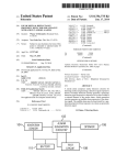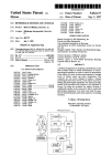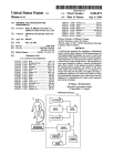
1
US 8,687,955 B2
Page 2
(56)
References Cited
US PATENT DOCUMENTS
4,827,347
5,008,497
5,287,138
5,701,527
A
A
A
A
5,708,882 A
5,729,289 A
5,845,161 A
5,900,856 A
5/1989
4/1991
2/1994
12/1997
Bell
Asher
Shiokama et a1‘
Sakabe et a1‘
V1998 Yokonumaet a1‘
3/1998 Etoh
12/1998 Schrocket al.
5/1999 Iino et a1.
2004/0240867 A1*
12/2004 Hara ............................. .. 396/55
2005/0219228 A1
10/2005 Alameh et al.
2005/0228320 A1
10/2005 Klinghult
2006/0022955 A1*
2/2006
Kennedy ..................... .. 345/173
2006/0092010
2006/0202925
2007/0030137
2007/0086764
5/2006
9/2006
2/2007
4/2007
Simon etal.
Manning et a1.
Masters et al.
Konicek
A1
A1
A1
A1
2007/0257890 A1*
11/2007 Hotelling etal. ........... .. 345/173
2008/0278454 A1
11/2008 Lee etal.
FOREIGN PATENT DOCUMENTS
5,923,908 A *
7/1999
5,949,484 A *
9/1999 Nakaya etal. .
348/384.1
JP
2000-2094g5 A
7/2000
6,016,407 A *
1/2000 Tsukahara .................. .. 396/302
JP
2000-333055 A
11/2000
JP
JP
JP
JP
JP
JP
2002_290g02
2003474640
2004-005320
2004420204
2005-072g0g
2006462974
10/2002
9/2003
1/2004
4/2004
3/2005
6/2006
6,148,148
6,298,197
6,459,424
6,492,979
6,519,419
6,558,050
6,628,336
6,888,574
A
B1
B1
B1
B2
B1
B2
Schrock et al. ............... .. 396/85
11/2000
10/2001
10/2002
12/2002
2/2003
5/2003
9/2003
Wain et al.
Wain etal.
Resman
Kent etal.
Shimada etal.
Ishibashi
Hamamura
5/2005 Asakura
B1
7,102,626 B2
9/2006 Denny, III
7,123,829 B2
10/2006 Ohsuga et a1~
7,283,738 B2 * 10/2007 Ohsuga et 31'
lgg‘rkrllligiet a1‘ """""""" " 348/352
834983531 B2 *
A
A
A
A
A
OTHER PUBLICATIONS
Minolta MaXXum Dynax 3X1 Instruction Manual, 1991, Part 1.
Minolta MaXXum Dynax 3X1 Instruction Manual, 1991, Part 2.
Nikon Digital CameraE300 CoolPiX 300 User’s Manual.
70013 Sakurai ““““““““““““ “ 396/303
Of?ce Action from European Search Report EP 06252534, dated
2003/0063073 A1
4/2003 Geaghan etal.
P69212911
2003/0081142 A1*
5/2003 Iijima ......................... .. 348/372
Sony Che Handbook, 2001
2003/0199995 A1
10/2003 Ishiiet al.
2004/0201772 A1
10/2004 Kobayashi
* cited by examiner
US. Patent
Apr. 1, 2014
Sheet 2 0f 16
FIG. 2A
FIG. 2B
US 8,687,955 B2
US. Patent
Apr. 1, 2014
Sheet 3 0f 16
FIG. 3A
FIG. 3B
US 8,687,955 B2
US. Patent
Apr. 1, 2014
Sheet 4 0f 16
FIG. 4
US 8,687,955 B2
US. Patent
Apr. 1, 2014
Sheet 6 6f 16
US 8,687,955 B2
FIG. 6
POWER-SUPPLY
OPERATION SIGNAL
OPERATION
SIGNAL OR DETECTION
SIGNAL?
DETECTION SIGNAL
S4
\’\
NO SIGNAL
I
NORMAL PROCESSING
(
BACKGROUND PROCESSING
CAPABLE OF IMAGE CAPTURING
YES
v
OPERATIOIIIIPOETIIITAIGCEFSIGNAL ‘85
PROCESSING SECTION
SHUTTER
OPERATING SIGNAL
RECEIVED?
IMAGE CAPTURING
CI-IANGING TO STATE
POWER-SUPPLY
SIGNAL RECEIVED IN
PREDETERMINED
TIME?
NO
5S2
)
AWAIT
RECEPTION
(TIMEOUT MODE)
US. Patent
Apr. 1, 2014
Sheet 7 0f 16
US 8,687,955 B2
FIG. 7
CONTACT
DETECTING
SENSOR
ATTITUDE
DETECTING
SENSOR
-I;J
I
___________I
ANALOG SIGNAL
A/D
CONVERTER —> COMPARATOR
INTERRUPTION
SIGNAL
ARITHMETIC
PROCESSING
SECTION
DATA
STORAGE
SECTION
DATA WRITING
DEVICE
(IN SHIPPING)
/
1s
17
US. Patent
Apr. 1, 2014
Sheet 8 0f 16
US 8,687,955 B2
FIG. 8
FROM STEP ST7 IN FIG. 9
ST1
NOT
SATISFIED
THRESHOLD
CONDITION SATISFIED BY
DETECTED VALUE?
CONDITION
SATISFIED
GENERATE INTERRUPTION SIGNAL
I
RESET ARITHMETIC
PROCESSING SECTION
(CANCEL SLEEP MODE)
I
TO STEP ST4 IN FIG. 9
5T3
5
US. Patent
Apr. 1, 2014
Sheet 9 0f 16
US 8,687,955 B2
FIG. 9
ST8
>
CANCEL SLEEP MODE OF
ARITHMETIC PROCESSING SECTION
FROM STEP ST3 IN FIG. 8
I
ST4
POWER
SUPPLY OPERATION SIGNAL
RECEIVED?
i
ST9
/
II
NORMAL PROCESSING
BACKGROUND PROCESSING
S 8T5
(CHANGING
TO STATE CAPABLE)
OF IMAGE CAPTURING
II
ST6
II
COMPLETION OF OPERATION 5 $T10
OF SYSTEM COMPONENT
POWER-SUPPLY
SIGNAL RECEIVED IN
PREDETERMINED
TIME?
NO
AWAIT
RECEPTION
(TIMEOUT MODE)
II
NO
Sm
SET ARITHMETIC PROCESSING 5 3T7
SECTION TO SLEEP MODE
SHUTTER
OPERATING SIGNAL
I
RECEIVED?
TO STEP ST1 IN FIG. 8
IMAGE CAPTURING
II
(
END
)
5 Sm
US. Patent
Apr. 1, 2014
Sheet 10 0f 16
US 8,687,955 B2
FIG. 10
12A\
DATADEVICE
WRITING /
18
(IN SHIPPING)
1,13A
I
‘I
j
16
i‘
'
\.\
DATA
I \
i
DETECTING UNIT i
I
STORAGE
|__ ATTITUDE DETECTING
'
T
CIRCUIT
'
i’ COMPARATOR‘L
i
CONTACT DETECTING
SENSoR
k
I
\\
,
|
I
CoNSTANT
-
I
I
\
I
L ________________ ._1.5_ ______________________ _I
BINARY SIGNAL
19
I
|
/./ 4b
TTTTTT —-—'—'—-—-—-—-—'—-—'—-—-—-—-—-—I
:
Y
i
INTERRUPTION
i
i
|
GENERATING —>
SECTIoN
L/
ARITHMETIC
I
PROCESSING
I
SECTION
:
I
US. Patent
Apr. 1, 2014
Sheet 11 0f 16
US 8,687,955 B2
FIG. 11
FROM STEP ST7 IN FIG. 9
ST20
NOT
SATISFIED
THRESHOLD
CONDITION SATISFIED BY
DETECTED VALUE?
CONDITION
SATISFIED
GENERATE INTERRUPTION
SIGNAL BASED ON BINARY SIGNAL
I
RESET ARITHMETIC
PROCESSING SECTION
(CANCEL SLEEP MODE)
I
TO STEP ST4 IN FIG. 9
Sm
5
US. Patent
Apr. 1, 2014
Sheet 12 0f 16
US 8,687,955 B2
FIG. 12
13B
I
1/’
|
/'/I
DETECTING UNIT
I
I
T i
|_ ATTITUDE DETECTING f
|
I
I
'
|
CIRCUIT
CONSTANT
SENSOR
I CONTACT DETECTING /
|
'
i
l
-
SERIAL
i
i
SENSOR
I —————— —-—
\15
I
,
I
I
l
i
_______________________________ __|
------------------- TI
'
AND-INTERRUPTION-
I GENERATING SECTION
I
,, 4b
I I’
! SERIAL-COMMUNICATION-
'
.
|
TTT
_
I/
N22
I
I
18
X
|
I
I
!
ARITHMETIC
I
I
PROCESSING ‘ sTORAGE <—I—
DEvICE
SECTION
SECTION
I (IN SHIPPING)
DATA
i
|
I' ___________
3a
:
COMMUNICATOR \41
i_ _______ __
'
I
!
i > COMPARATO\R;
'
3b
______ _'_\x_'_'_:
16
DATA WRITING
US. Patent
Apr. 1, 2014
Sheet 13 0f 16
US 8,687,955 B2
FIG. 13
FROM STEP ST7 IN FIG. 9
ST30
NOT
SATISFIED
THRESHOLD
CONDITION SATISFIED BY
DETECTED VALUE?
CONDITION
SATISFIED
GENERATE SERIAL COMMUNICATION
INTERRUPTION SIGNAL
5ST31
I
RESET ARITHMETIC
PROCESSING SECTION
(CANCEL SLEEP MODE)
I
TO STEP ST4 IN FIG. 9
Sm
5
US. Patent
@
t
@
I
Apr. 1, 2014
Sheet 14 0f 16
US 8,687,955 B2
Q
@
A
E,.OE
EV
E EE EE
g
EE E m
US. Patent
Apr. 1, 2014
Sheet 15 0f 16
US 8,687,955 B2
FIG. 15
FROM STEP ST7 IN FIG. 9
ST40
NOT
SATISFIED
THRESHOLD
CONDITION SATISFIED BY
CONTACT DETECTION
VALUE?
CONDITION
SATISFIED
ST41
NOT
SATISFIED
THRESHOLD
CONDITION SATISFIED BY
ATTITUDE DETECTION
VALUE?
CONDITION
SATISFIED
GENERATE INTERRUPTION SIGNAL
I
RESET ARITHMETIC
PROCESSING SECTION
(CANCEL SLEEP MODE)
I
TO STEP ST4 IN FIG. 9
ST43
5
US. Patent
Apr. 1, 2014
Sheet 16 0f 16
US 8,687,955 B2
FIG. 16
(
START )
>=
FROM STEP
ST? IN FIG. 9
!' ___________________ "KT'TTTUSEI _______________ mmmméb??é?
DETECTION I
DETECTION!
ST50
ST53
THRESHOLD
CONDITION SATISFIED BY
DETECTED VALUE?
' NOT
THRESHOLD
CONDITION SATISFIED BY
DETECTED VALUE?
NOT
SATISFIED
SATISFIED ST51
/\/
GENERATE
INTERRUPTION SIGNAL
I SATISFIED
SATISFIED ST54
GENERATE
INTERRUPTION SIGNAL
ST52 |
ST55
II
II
/\/
|
RESET ARITHMETIC
PROCESSING SECTION
PROCESSING
RESET ARITHMETIC
SECTION
i
(CANCEL SLEEP MODE)
(CANCEL SLEEP MODE)
i
|
|
L
_
_
_
_
_
_
_
_
_
_
_
_
_
_
_
_
_
_
_
_
_
_
_
_
_
_
TO STEP ST4 IN FIG. 9
_
_
_
_
__4
L
_
_
_
_
_
_
_
_
_
_
_
_
_
_
_
_
_
_
_
_
_
_
_
_
_
_
_
TO STEP ST4 IN FIG. 9
_
_
_
___|
US 8,687,955 B2
1
2
IMAGE CAPTURING DEVICE AND
ACTIVATION METHOD THEREFOR
release opportunity include a situation in Which, When the
CROSS-REFERENCES TO RELATED
APPLICATIONS
poWer of the device is off at the time the user ?nds a desired
subject, the user fails to capture an image of a subject due to
a long time taken after the user holds the device until the
For example, cases in Which the user misses a shutter
device is ready for image capturing. In other Words, a time
necessary for activation after pressing the poWer supply
This application is a continuation of Us. application Ser.
No. 13/531,967, ?led on Jun. 25, 2012, Which is a continua
tion ofU.S. application Ser. No. 12/380,842, ?led on Mar. 4,
2009, Which is a continuation of Us. application Ser. No.
11/434,542 ?led on May 15, 2006 in the Us. Patent and
Trademark O?ice Which claims priority from Japanese Patent
Application No. JP 2005-142965 ?led in the Japanese Patent
O?ice on May 16, 2005, the entire contents of Which are
sWitch is no more than approximately one second, even if the
activation is fast, so that it is dif?cult to capture an image of a
subject (or the like) passing in a moment. This is because it is
dif?cult to reduce the activation time to Zero in an actual
device. To prevent the user from missing the shutter release
opportunity, the system poWer needs to be continuously on or
the device needs to be in a suspend state. The suspend state
means a state in Which, although an operation of a control unit
incorporated herein by reference.
BACKGROUND OF THE INVENTION
The present invention relates to a technology, used in an
20
image capturing device, for enhancing its activating function
such as a CPU (central processing unit) is stopped, the poWer
of each portion of the system is on.
As described above, to reduce the activation time close to
Zero, an increase in poWer consumption is extremely impor
tant and necessary in compensation for the reduction. There
fore, When a battery-driven portable device is used, it is nec
ality so as not to fail to capture a desired image of a subject or
essary for a user to carry many charged batteries or to use a
the like and preventing unnecessary poWer consumption in a
standby state of the image capturing device before it enters an
mass storage battery. In a digital camera or the like, a device
image capturing mode.
A camera-device con?guration (see, for example, Japanese
25
Unexamined Patent Application Publication No. 2003
274640) is knoWn Which shortens an activation time that is
necessary from the time a poWer-on operation is performed
poWer-saving function is important for capturing as many
images as possible. Thus, shortening of the activation time
and the need of poWer saving con?ict With each other.
Accordingly, it is desirable to satisfy both an improvement
in activating functionality and poWer saving in an image
capturing device.
on a camera device until the camera device is actually 30
SUMMARY OF THE INVENTION
sWitched on for use.
When a poWer supply switch is operated, chattering in
Which intermittent opening and closing of a contact is repeat
edly performed occurs, thus causing a false operation, etc.
Accordingly, after a time passes until effects of the chattering
To solve the above problems, according to an embodiment
35
of the present invention, there is provided an image capturing
device including ?rst control means for controlling image
disappear, a process (so-called “chattering preventing pro
cess”) that determines Whether the poWer supply sWitch is
capturing, the ?rst control means having a ?rst poWer con
opened or closed is performed. In addition, When it is deter
mined that the poWer-on operation has been performed, a
means for detecting a change to an image capturing mode and
system initialiZing process is performed after poWer supplied
by a system’s poWer supply unit becomes stable. After that,
sumption; operation means including a sWitch; detecting
40
for sending a signal representing the change to the image
capturing mode; second control means for monitoring and
processing the signal sent from the detecting means, the sec
the camera device is in a state capable of processing such as
ond control means having a poWer consumption less than the
image capturing. In other Words, it is dif?cult to perform an
?rst poWer consumption; and a poWer supply for supplying
operation or processing desired by a user unless a time rep
resented by “T1+T2+T3” passes after a poWer-supply opera
tion time at Which a poWer-supply operation is performed,
Where T1 represents a time necessary for the chattering pre
venting process, T2 represents a time necessary until the
poWer to the ?rst control means, the second control means,
45
ing by supplying poWer from the poWer supply to portions of
poWer supplied by the poWer supply unit becomes stable, and
T3 represents a time necessary for the system initialiZing
50
process.
Therefore, by performing the chattering preventing pro
55
desired by the user is initiated can be shortened. In other
Words, by employing a sequence that performs system initial
iZation as background processing for the chattering prevent
ing process, after the poWer is supplied to the system, the
system can be initialiZed Without Waiting for the chattering
preventing process to ?nish. For example, When T1<T3, the
According to another embodiment of the present invention,
there is provided an activation method for an image capturing
device having a function of controlling poWer supplying
states including a ?rst poWer control state capable of image
capturing, the ?rst poWer control state having a ?rst poWer
consumption, and a second poWer control state having a
60
poWer consumption less than the ?rst poWer consumption.
The activation method includes, in the second poWer control
state, monitoring a sWitch operation and a change to an image
capturing mode; and, When the change to the image capturing
activation time can be shortened to a time represented by
“T2+T3” or approximately a time obtained by adding some
value to “T2+T3.”
HoWever, the image capturing device of the related art has
the image capturing device including the ?rst control means
When the second control means receives the signal represent
ing the change to the image capturing mode from the detect
ing means.
cess after turning on the poWer supply sWitch and the system
initialiZing process in parallel, an activation time from the
poWer-supply operation time until the operation or processing
and a functional section of the image capturing device.
In the image capturing device, a poWer saving state is
changed to a poWer supplying state capable of image captur
mode is detected in the second poWer control state, changing
the second poWer control state to the ?rst poWer control state.
65
Accordingly, in an embodiment of the present invention, at
the folloWing problems in its activating functionality and
the time a second control means receives a detection signal
poWer saving function.
representing a change (changing start) to an image capturing
US 8,687,955 B2
4
3
mode, power supply control for enabling image capturing is
FIG. 4 is an illustration of attitude detection in a camera
performed. After changing to a ?rst power control state,
image capturing is immediately initiated. In a second power
control state, power is supplied only to the second control
means and power does not need to be continuously supplied
according to an embodiment of the present invention;
FIG. 5 is an illustration of examples of screens for activa
tion settings;
FIG. 6 is a ?owchart showing a system activating process;
FIG. 7 is a block diagram showing a main part of a con
to the ?rst control means and the second control means. This
contributes to reducing power consumption in a standby state
?guration example;
before image capturing.
FIG. 8 is a ?owchart showing an example of an activation
process;
FIG. 9 is a ?owchart showing a process ?ow continued
According to an embodiment of the present invention, by
initiating preparation for image capturing at the time the
setting of an image capturing mode is detected, activating
from FIG. 8;
FIG. 10 is a block diagram showing a main part of another
functionality can be enhanced. In addition, it is not necessary
to set a power supplying state capable of image capturing at
con?guration example;
all times. When image capturing is not performed, by setting
FIG. 11 is a ?owchart showing a main part of an example of
a standby state having low power consumption, a power sav
ing effect can be obtained. In other words, since it is di?icult
to reduce an activation time itself to Zero, by changing to the
?rst power control state while using, as a start point, the time
a system activation process concerning the con?guration
shown in FIG. 10;
FIG. 12 is a block diagram showing a main part of still
another example con?guration;
the change to the image capturing mode is detected, both an
improvement in activating functionality and power saving
20
For example, after changing to a power supplying state
capable of image capturing, when a power supplying opera
vation;
tion is not performed, or a signal representing a change to an
image capturing mode is not detected, by shutting off power
25
supplied to the ?rst power control means to change to the
power saving state, power consumption in the standby state
can be reduced. In other words, after changing to the ?rst
power control state, when a power supplying operation is not
performed, or a signal representing a change to an image
a system activation process in a case in which a maximum
30
no intention of image capturing or a high probability of no
intention, it is preferable to change to the second power con
35
In an embodiment of the present invention, by immediately
controlling power supply when detecting setting of an image
capturing mode with a detecting unit such as an electrostatic
means for detecting the change to the image capturing mode,
when it is detected, as a preliminary image capturing step, that
the image capturing device is touched by a user, the device
40
according to a con?guration in which a sensor for detecting a
change in the attitude of a body of the device is provided as the
detecting means, when it is detected, as a preliminary image
capturing step, that the image capturing device is held or
moved by the user, the device can be changed to the ?rst
power control state. Furthermore, by employing a detecting
speed mode is set.
DETAILED DESCRIPTION
trol state (power saving state).
can be changed to the ?rst power control state. Alternatively,
FIG. 15 is a ?owchart showing a main part of an example of
a system activation process in a case in which a high speed
mode is set; and
FIG. 16 is a ?owchart showing a main part of an example of
capturing mode is not detected, by determining that there is
In addition, according to a con?guration in which a sensor
for detecting contact with a device is provided as the detecting
FIG. 13 is a ?owchart showing a main part of an example of
a system activation process concerning the con?guration
shown in FIG. 12;
FIG. 14 is an illustration of examples of settings for acti
can be achieved.
45
sensor or angular velocity sensor, image capturing can be
initiated after necessary processing such as initialization. For
example, at the time a user holds a camera, supplying of
power to each portion of a camera system and an initialiZing
process are initiated, whereby it takes almost no waiting time
after operating a power supply switch until operating a shutter
release button. This can prevent occurrence of a situation in
which the user misses a shutter release opportunity. An
embodiment of the present invention is widely applicable to
form that is a combination of these sensors, detection accu
still cameras and camcorders, or to various types of image
racy can su?iciently be enhanced.
In order to obtain a power saving effect in a standby state in
capturing devices that can capture still and moving images.
which image capturing is not performed, it is preferable that,
FIG. 1 shows an example of a basic con?guration of an
50
image capturing device according to an embodiment of the
present invention.
An image capturing device 1 includes an operation unit 2
including power supply switches and a detecting unit 3 using
55
nals sent from these sensors are sent and processed in a
when the second control means receives a signal representing
a change to an image capturing mode from detecting means,
a power-supply-instruction signal be sent from the second
control means to a power supply after a resting state of the
second control means is canceled.
an electrostatic sensor, an angular velocity sensor, etc. Sig
BRIEF DESCRIPTION OF THE DRAWINGS
FIG. 1 is a block diagram showing an example of a basic
con?guration of an image capturing device according to an
embodiment of the present invention;
FIGS. 2A and 2B are perspective views showing contact
60
detection in a camera according to an embodiment of the
present invention;
FIGS. 3A and 3B are illustrations of a different example of
the contact detection in a camera according to an embodiment
of the present invention;
system controller 4.
The operation unit 2 includes various types of operation
buttons and switches provided on the image capturing device
1. In FIG. 1, only power supply switches 2a and 2b are shown.
An operation signal from a power supply switch (or a power
switch) serves as a trigger signal for supplying power. When
an embodiment of the present invention is applied to, for
example, a digital still camera, the number of power supply
switches is not limited to one depending on a con?guration
65
form, but there is a system including a plurality of power
supply switches. In this embodiment, two switches are
shown.
US 8,687,955 B2
5
6
The detecting unit 3 is provided to detect a change in mode
to an image capturing mode. The detecting unit 3 may have
the image capturing device 1. In this embodiment, an image
signal processing section 511 and an image display section 5b
are shoWn as typical examples. The image signal processing
the following forms:
(I) form using sensor for detecting contact With image cap
turing device 1;
section 511 includes an image capturing unit, a camera signal
processor, and a recording-and-playback-system signal pro
(II) form using sensor for detecting change in attitude of
cessor, and performs image capturing, and image recording
image capturing device 1; and
(III) form Using form (I) and form (II).
and playback, and, in the image display section 5b, an LCD
(liquid crystal display) panel or the like is used.
A poWer supply 6 supplies poWer to the ?rst control unit 4a,
the second control unit 4b, and the system con?guration unit
At ?rst, in form (I), for example, a contact detecting sensor
311 such as an electrostatic sensor is used. The contact detect
ing sensor 311 detects contact of a user With the image captur
5. In application of an embodiment of the present invention, a
ing device 1, and sends a signal of the detection to the system
poWer supply 611 in Which, for example, a battery (primary
controller 4. Excessive detection sensitivity causes a situation
in Which slight contact With the image capturing device 1
performs poWer supplying for activation, so that the fre
quency of false detection increases, etc. Thus, it is preferable
battery or secondary battery), a fuel cell, or the like, is used,
and a poWer-supply voltage generating section 6b (such as a
to appropriately set the detection sensitivity to ensure contact
detection.
necessary for each circuit are provided irrespective of the
circuit con?guration of the poWer supply 6. The poWer-sup
DC-DC converter) for generating a poWer-supply voltage
attitude detecting sensor 3b detects a change in device attitude
ply voltage generating section 6b supplies poWer to each
circuit through poWer-supply lines.
In this embodiment, When the poWer supply 611 supplies
When the image capturing device 1 is held or moved by the
poWer to the poWer-supply voltage generating section 6b in a
Also in the above form (II), an attitude detecting sensor 3b,
such as an angular velocity sensor or gyrosensor, is used. The
20
state in Which a battery pack or the like is installed in the
user, and sends a signal of the detection to the system con
troller 4. Cases to Which an embodiment of the present inven
tion is applied include a form in Which, not only the angular
25
unit 4b can be immediately performed.
The second control unit 4b has poWer consumption less
than that of the ?rst control unit 4a. This is because, since the
second control unit 4b handles monitoring and processing the
velocity sensor, but also an acceleration sensor is used as a
sensor capable of measuring a change in speed, and a form in
Which detection accuracy is enhanced by using a vibration
sensor to increase the number of detection axes. Alternatively,
in a camera device having an image stabiliZing function, by
30
using an angular velocity sensor and acceleration sensor pro
vided for image stabilization to detect a change in device
attitude, a detecting unit can be mounted Without increasing
the number of components and expense.
Improvement of the detection accuracy includes a method
35
that uses a plurality of sensors of the same type in the above
forms (I) and (II), and a method that uses sensors of different
types in combination, as in form (III). When determination is
multilaterally performed, the latter is more effective.
In FIG. 1, for brevity of description, form (III) is assumed,
40
and an example of the detecting unit 3 in Which it includes
sensors of plural types is shoWn. In addition, forms of trans
mission from the detecting unit 3 to the system controller 4
include analog transmission and digital transmission (includ
ing binariZation communication and serial communication),
45
second control unit 4b, a consumption current is set to hun
dred microamperes or less.
Unlike that, an arithmetic operation unit having a ?xed
operating frequency, or an arithmetic operation unit in Which
poWer control can be performed by variably controlling an
operating frequency is used as the ?rst control unit 4a. When
acceleration of processing or the like is preferentially per
formed, the poWer consumption of the ?rst control unit 411
of image capturing at all times by performing a poWer-supply
operation (by the user) to supply poWer to the ?rst and second
control units 411 and 4b, and the system con?guration unit 5,
a situation in Which the user misses a shutter release oppor
tunity can be avoided. HoWever, poWer consumption in the
above case is large, thus shortening a time in Which the image
capturing device 1 can be battery-driven. Accordingly, in the
a second control unit 4b. The con?guration of the system
controller 4 has, for example, the folloWing forms:
50
standby state before image capturing, by supplying poWer
from the poWer supply 611 to the second control unit 4b having
less poWer consumption, a poWer saving effect can be
obtained.
circuit; and
a form in Which the system controller 4 is formed as a
single chip and circuit portions having functions of both
control units are formed in the single chip.
In either form, the ?rst control unit 411 controls image
operation signal and the detection signal, unnecessary poWer
consumption is prevented in a standby state before image
capturing. When, for example, a microcomputer is used as the
increases than that of the second control unit 4b. In other
Words, if the image capturing device 1 is set in a mode capable
Whose details are described later.
The system controller 4 includes a ?rst control unit 411 and
a form in Which each control unit is formed as a separate
image capturing device 1, poWer supply from the poWer
supply voltage generating section 6b to the second control
In an embodiment of the present invention, in a poWer
55
saving mode in Which poWer is supplied from the poWer
capturing, or recording or playback of captured image data,
supply 611 to the poWer-supply voltage generating section 6b,
and the second control unit 4b monitors and processes an
When the second control unit 4b receives, from the detecting
unit 3, a signal representing a change in mode to the image
capturing mode, the poWer supply 6 supplies poWer to the ?rst
control unit 411 and the system con?guration unit 5, and the
poWer saving mode subsequently changes to a poWer supply
operation input signal from the operation unit 2 and a detec
tion signal from the detecting unit 3. For example, a micro
computer or the like may be used as the ?rst control unit 4a.
60
For example, an application speci?c IC (integrated circuit), a
microcomputer (used as a sub-computer for a main-computer
ing state capable of image capturing. Speci?cally, poWer con
used as the ?rst control unit 4a), or the like, may be used as the
second control unit 4b.
In a system con?guration unit 5 under the control of the
trol states of the image capturing device 1 include at least the
?rst control unit 4a, various types of components are used
depending on the speci?cations and system con?guration of
folloWing states:
65
a ?rst poWer control state (hereinafter referred to as “IS”)
in Which the image capturing device 1 is capable of image
capturing; and