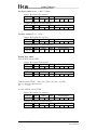
1
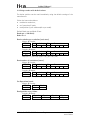
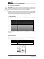
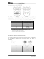
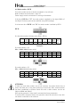
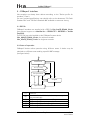
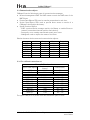
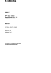
Ax58x CANopen®
User manual
Ax58x CB
CCCB, CCCBC
Chapters
1
2
3
4
5
6
Safety summary
Identification
Quick reference
Electrical connections
CANopen® interface
Setup
DS 406 - Device profile for encoders
1 Safety summary
Safety
• observe the professional safety and accident prevention regulations applicable to your
country during device installation and operation;
• installation has to be carried out by qualified personnel only, without power supply and
stationary shaft;
• the encoder must be used only for the purpose appropriate to its design;
• high current, voltage and rotating parts can cause serious or fatal injury.
Electrical safety
• switch OFF the voltage before connecting the device;
• connect according to the chapter 4: “Electrical connections”;
• according to the 89/336/CEE norm on electromagnetic compatibility, following
precautions must be taken:
- before handling and installing, discharge electrical charge from your body and tools which
may come in touch with the device;
- power supply must be stable without noise, install EMC filters on device power supply if
needed;
- always use shielded and twisted cables if possible;
- avoid cables runs longer than necessary;
- avoid running the signal cable near high voltage power cables;
- mount the device as far as possible from any capacitive or inductive noise source, shield the
device from noise source if needed;
- minimize noise by connecting shield or connector housing to ground (GND). Make sure that
ground (GND) is not affected by noise. The shield connection point to ground can be
situated both on the device side and on user’s side. The best solution to minimize the
interference must be carried out by the user.
Mechanical safety
• solid shaft: use a flexible coupling to connect encoder to motor shaft respecting the
coupling misalignment tolerances;
• do not disassemble the encoder;
• do not tool the encoder or its shaft;
• do not subject the encoder and the shaft to knocks or shocks;
• respect the environmental characteristics of the product.
MAN Ax58x CB DS406 E 2.7.doc
Pag.1
www.lika.it
www.lika.biz
Ax58x CANopen®
2 Identification
The device can be identified by the label's data (ordering code, serial number).
This information is listed in the delivery document. For technical features of the
product, refer to the technical catalogue.
3 Quick reference
3.1 Hardware resolution
ATTENTION:
Make sure the physical resolution corresponds to the resolution set in
parameters.
There may be different resolutions set if encoder and connection cap have been
ordered/ supplied separately.
Examples:
ASx58x 12/CB-xx
ASx58x 13/CB-xx
AMx58x 12/4096CB-xx
AMx58x 13/4096CB-xx
steps/rev. = 4096,
steps/rev. = 8192,
steps/rev. = 4096,
steps/rev. = 8192,
n° rev. = 1.
n° rev. = 1.
n° rev. = 4096.
n° rev. = 4096.
Hardware counts per revolution is in object 6501 hex.
Hardware number of turns is in object 6502 hex.
If hardware resolution doesn’t match ordering code (see encoder label) the
procedure to set hardware resolution must be do (how to read hardware
resolution see chapter 3.2).
It’s important to observe that the parameters 6001 hex and 6002 hex are related
to the scaling function, but the correct working is guaranteed only if the
hardware resolution is set correctly.
Procedure to set hardware resolution
ID = node identifier.
Step 1 Access to the configuration (ogg. 3002h)
Note: to avoid unintentional access, this object is not on EDS file.
Master Encoder
COBID
Cmd
600+ID
23
Index
02
30
Sub
00
Process data
41 4B 49 4C
Encoder Master
COBID
Cmd
580+ID
60
Index
02
30
Sub
00
Process data
00 00 00 00
MAN Ax58x CB DS406 E 2.7.doc
Pag.2
www.lika.it
www.lika.biz
Ax58x CANopen®
Step 2 Set object 6501h: Hardware counts per revolution
See resolution table for B0, B1, B2, B3 values.
Master Encoder
COBID
Cmd
600+ID
23
Index
01
65
Sub
00
Process data
B0 B1 B2 B3
Encoder Master
COBID
Cmd
580+ID
60
Index
01
65
Sub
00
Process data
00 00 00 00
Step 3 Set object 6502h: Hardware number of turns
See resolution table for B4, B5, B6, B7 values.
Master Encoder
COBID
Cmd
600+ID
23
Index
02
65
Sub
00
Process data
B4 B5 B6 B7
Encoder Master
COBID
Cmd
580+ID
60
Index
02
65
Sub
00
Process data
00 00 00 00
Step 4 Send a “Reset node”
Master Encoder
COBID
Cmd
000
81
Slave ID
ID
Step 5 Store parameters (ogg. 1010h)
Master Encoder
COBID
Cmd
600+ID
23
Index
10
10
Sub
01
Process data
73 61 76 65
Encoder Master
COBID
Cmd
580+ID
60
Index
10
10
Sub
01
Process data
00 00 00 00
Resolution table:
Encoder type
B0
ASx58x 12/CB-xx
00
ASx58x 13/CB-xx
00
AMx58x 12/4096CB-xx 00
AMx58x 13/4096CB-xx 00
MAN Ax58x CB DS406 E 2.7.doc
steps/rev.
B1 B2
10 00
20 00
10 00
20 00
Pag.3
B3
00
00
00
00
B4
01
01
00
00
n° rev.
B5 B6
00 00
00 00
10 00
10 00
B7
00
00
00
00
www.lika.it
www.lika.biz
Ax58x CANopen®
3.2 Using encoder with default values.
The device position can be read immediately using the default settings of the
manufacturer.
Follow the instructions below:
• read device resolution;
• set “operational” mode;
• read position (cyclic mode and/or sync mode).
Default Baud rate and Node-ID are:
Baud rate = 500 Kbit/s
NodeID = 1
Read resolution per revolution (each turn)
Master Encoder
COBID
Cmd
Index
Sub
601
40
01
65
00
-
Process data
-
Encoder Master
COBID
Cmd
Index
Sub
Process data
581
43
01
65
01 A0 A1 A2 A3
steps/rev. = ( (A3<<24) | (A2<<16) | (A1<<8) | A0 )
Read number of revolutions (turns)
Master Encoder
COBID
Cmd
Index
601
40
02
65
Sub
00
Process data
-
Encoder Master
COBID
Cmd
Index
Sub
Process data
581
43
02
65
01 B0 B1 B2 B3
N. rev. =( (B3<<24) | (B2<<16) | (B1<<8) | B0 )
Set Operational mode
Master Encoder
COBID
Cmd
000
01
Node
01
Read position every 100ms
Encoder Master
COBID
Byte 0
181
Low
Byte 1
…
MAN Ax58x CB DS406 E 2.7.doc
Pag.4
Byte 2
…
Byte 3
High
www.lika.it
www.lika.biz
Ax58x CANopen®
4 Electrical connections
ATTENTION: do not remove or mount the connection cap with power supply
switched ON. Damage may be caused to internal components. Make sure that
the encoder body and connection cap are at the same potential.
Minimize noise by connecting shield or connector housing to ground (GND).
Make sure that ground (GND) is not affected by noise. It’s recommended to
provide the ground connection as close as possible to the encoder.
4.1 LED diagnostics
Two LEDs on the rear of the connection cap show the status of the CANopen®
interface.
GREEN LED
ON
Single flash
Blinking
Description
Encoder is in Operational state
Encoder is in Stopped state
Encoder is in Pre-Operational state
RED LED
ON
Double flash
Single flash
Blinking
OFF
Description
The CAN controller is switched off
Node guarding error
Max. number of warnings error
Generic error or flash memory error
No error
During initialization the device carries out a hardware test to check LED
function.
4.2 Bus termination
A bus termination resistance is provided in the connection cap. This has to be
activated as line termination on the last device.
Use RT Switch to activate or deactivate bus termination.
RT
1 = 2 = ON
1 = 2 = OFF
Description
Activated: if the encoder is the last device
Deactivated: if the encoder is not the last
device
MAN Ax58x CB DS406 E 2.7.doc
Pag.5
www.lika.it
www.lika.biz
Ax58x CANopen®
4.3 Connection cap with PGs (CCCB)
The CC-CB connection cap has 3 cable glands PG9 for bus-IN, bus-OUT and
supply voltage connections. The bus cables can be connected directly to the
clamps in front of each cable gland. It's recommended to use CANbus
certificated cables. Core diameter should not exceed Ø1,5mm (0.06inch).
Clamp
+
G
L
H
PG
Description
0 Vdc Supply voltage
+10Vdc +30Vdc Supply voltage
CAN GND 1
CAN Low
CAN High
CAN Shield 2
1
: CAN GND is the 0V reference of CAN signals, it is not
connected to 0Vdc supply voltage.
2
: connected cable shield to cable gland.
4.4 Conn. cap with M12 connectors (CCCBC)
The CC-CB-C connection cap has two M12 connectors with pin-out according
to the CANopen® standard. Users can directly connect CAN cables for
commerce.
M12 connector
A coding
(frontal side)
M12
1
2
3
4
5
MAN Ax58x CB DS406 E 2.7.doc
male
female
(BUS IN)
(BUS OUT)
Description
CAN Shield
+10Vdc +30Vdc Supply voltage
0 Vdc Supply voltage
CAN High
CAN Low
Pag.6
www.lika.it
www.lika.biz
Ax58x CANopen®
4.5 Baud rate: DIP A
The transmission rate can be set both by hardware or by software.
If DIP A bit 4 = ”OFF” the bit rate is defined by object 3000h of the Object
Dictionary and can be modified using SDO messages.
If DIP A bit 4 = ”ON” the bit rate is defined by DIP A.
DIP A:
Set binary value of transmission rate considering: ON=1, OFF=0. The device must
be switched off!
1 LSB
20
bit
3 MSB
22
2
21
4
ON/OFF
Baud rate value table:
Decimal value
0
1
2
3
4
5
6
7
Binary value
000
001
010
011
100
101
110
111
Baud rate
20 Kbit/s
50 Kbit/s
100 Kbit/s
125 Kbit/s
250 Kbit/s
500 Kbit/s
800 Kbit/s
1000 Kbit/s
Example:
Set 250Kbit/s:
410 = 1002 (binary value, see previous table)
bit
1
20
OFF
2
21
OFF
3
22
ON
4
23
ON
Set 500Kbit/s:
510 = 1012 (binary value, see previous table)
bit
1
20
ON
2
21
OFF
MAN Ax58x CB DS406 E 2.7.doc
3
22
ON
Pag.7
4
23
ON
www.lika.it
www.lika.biz
Ax58x CANopen®
4.6 Node number: DIP B
The node number can be set both by hardware or by software.
Node numbers can be between 1 and 127.
Power supply must be switched off if setting via hardware.
If all bits of DIP B are ”OFF” the node number is defined by the object 3001h of
the Object Dictionary and can be modified using SDO messages.
If at least one bit of DIP B is set “ON” the node number is defined by DIP B.
DIP B:
Set the node number in binary value: ON=1, OFF=0
bit
1
LSB
20
2
3
4
5
6
25
7
MSB
26
8
not
used
21
22
23
24
4
23
ON
5
24
ON
6
25
OFF
7
26
OFF
8
4
23
OFF
5
24
ON
6
25
ON
7
26
OFF
Example:
Set node number = 25:
2510 = 0001 10012 (binary value)
bit
1
20
ON
2
21
OFF
3
22
OFF
OFF
Set node number = 55:
5510 = 0011 01112 (binary value)
bit
1
20
ON
2
21
ON
3
22
ON
8
OFF
ATTENTION:
If baud rate and node number are set via software, the master device has to
detect the baud rate of the slave (scanning of baud rate). Once communication
has been established a different baud rate and a node number can be set
(objects 3000h and 3001h).
After setting transmit a "reset node" command and store parameters.
To avoid conflict between Slaves, this operation should be carried out only with
one device connected to the network.
MAN Ax58x CB DS406 E 2.7.doc
Pag.8
www.lika.it
www.lika.biz
Ax58x CANopen®
5 CANopen® interface
Lika encoders are always slave devices according to the “Device profile for
encoders”, Class 2.
For every omitted specification, user should refer to the documents “CiA Draft
Standard 301” and “CiA Draft Standard 406” available on www.can-cia.org.
5.1 EDS file
CANopen® encoders are supplied with a EDS file Lika_AxxCB_DS406_V3.eds
(see enclosed support or www.lika.biz > PRODUCTS > ROTACOD > Ax58x
EasyCAN).
The EDS file has to be installed on the CANopen® master device.
Lika_AMxCB_DS406_V3.eds: for multiturn encoder.
Lika_ASxCB_DS406_V3.eds: for singleturn encoder.
5.2 States of operation
CANopen® devices allow operation using different states. A device may be
switched to a different state sending a specific NMT message.
(see figure below)
(1)
Initialization
(2)
Boot-up message
(6)
Pre-operational
(3)
(5)
(4)
(6)
Stopped
(6)
(4)
(5)
(3)
Operational
(1)
(2)
(3)
(4)
(5)
(6)
Power on
State initialization finished, the boot-up message is
sent automatically
NMT message: ”Start remote node”
NMT message: ”Enter pre-operational”
NMT message: ”Stop remote node”
NMT message: ”Reset node” or “Reset comm.”
MAN Ax58x CB DS406 E 2.7.doc
Pag.9
www.lika.it
www.lika.biz
Ax58x CANopen®
5.2.1 Initialization
This is the first state the CANopen® device enters after power-on or hardware
reset. After finishing the basic CANopen® device initialization the device reads
the parameters stored in EPROM, sends a boot-up message and then enters
automatically into the “Pre-operational” state.
5.2.2 Preoperational state
In this state communication is possible using SDOs. Communication using PDOs
is not possible in this status.
Configuration of PDOs and parameters may be performed using a configuration
software.
The device can be switched into the Operational state directly by sending a
“Start remote node” message.
5.2.3 Operational state
In this state all communication objects are active. The manufacturer uses the
parameters as described in the object dictionary and may sent process data
using PDO.
Object dictionary can be accessed using SDOs.
The device can be switched into the Pre-operational state directly by sending a
“Enter pre-operational” message.
5.2.4 Stopped state
In this state the device is forced to stop communication with the Master (except
node guarding, if active).
Communication by PDO and SDO is not possible.
The device can be switched into the Operational state or Pre-operational state
directly by sending the specific NMT message.
MAN Ax58x CB DS406 E 2.7.doc
Pag.10
www.lika.it
www.lika.biz
Ax58x CANopen®
5.3 Communication objects
CANopen® has the following 4 types of communication messages:
• Network management NMT: the NMT master controls the NMT state of the
NMT Slaves.
• Process Data Objects PDO: used to transfer process data in real-time.
• Service Data Objects SDO: used to provide direct access to entries of a
CANopen® device object dictionary.
• Special Function Objects:
- SYNC: synchronization message used by the Master to enable Slaves to
transmit process data (encoder position and velocity).
- Emergency: error message transmitted at each error event.
- Nodeguard: used to request the status of the Slave.
Relation between device states and communication objects:
Initial.
NMT
PDO
SDO
SYNC
EMCY
Boot-up
Nodeg.
Pre-oper.
X
Stopped
X
X
Operat.
X
X
X
X
X
X
X
X
X
X
5.3.1 Predefined connection set
Master Slave broadcast
Function code
COB-ID (hex)
type of COB (Object)
(binary)
NMT
0000
000
SYNC
0001
080
EMERGENCY
PDO 1 (tx)
PDO 2 (tx)
PDO 3 (tx)
SDO (tx)
SDO (rx)
Nodeguard
Boot-up
peartopear transmission
0001
0011
0101
0111
1011
1100
1110
1110
081 - 0FF
181 - 1FF
281 - 2FF
381 - 3FF
581 - 5FF
601 - 67F
701 - 77F
701 - 77F
The type of COB (tx or rx) is seen from the slave device point of view.
MAN Ax58x CB DS406 E 2.7.doc
Pag.11
www.lika.it
www.lika.biz
Ax58x CANopen®
5.4 NMT objects
NMT structure:
COBID (11 bit)
Func.code Node ID
0000
0
2 CAN Data Bytes
Command
Slave ID
NMT Func.
Slave ID
if Slave ID = 00h, the NMT message is directed to all network node.
NMT Function:
Command
01 hex
02 hex
80 hex
81 hex
82 hex
NMT Function
Start remote node
Stop remote node
Enter pre-operational
Reset node
Reset communication
Status node
Operational
Stopped
Pre-operational
Pre-operational
Pre-operational
5.5 Bootup objects
Boot-up message structure:
COBID(hex)
700+Node ID
MAN Ax58x CB DS406 E 2.7.doc
1 CAN Data Bytes
00
Pag.12
www.lika.it
www.lika.biz
Ax58x CANopen®
5.6 PDO objects
PDO (tx) messages are always composed by 4 CAN Data Bytes and are used by
the encoder to transmit the position value.
PDO structure:
IDENTIFIER
COB-ID(hex)
F.C.
Node-ID
Byte 0
Low
4 CAN Data Bytes
Byte 1
Byte 2
…
…
position value
Byte 3
High
PDO1 Cyclic mode: cyclic transmission
The encoder uses the PDO1 to transmit the position value periodically and
independently from the Master.
The cycle time is defined by the parameter “Cyclic Time” (object 6200h).
To activate (or deactivate) cyclic mode it's necessary to set to 0 (or 1) the most
significant bit of COB-ID used by the PDO1 (object 1800h, sub 1).
PDO2 and PDO3 SYNC mode: synchronous transmission.
The transmission is managed by the Master by sending a SYNC message.
The SYNC is a high-priority COB transmitted by the Master to request the
position value of encoder.
If several nodes (encoders) are connected to a network, the Master receives the
position values in order of Node nr.
The encoder can programmed to reply after a number "n" of SYNC messages by
setting a counter.
The PDO will be transmitted after having received "n" SYNC messages.
For PDO2 the value "n" of counter must be specified in object 1801h, sub 2.
For PDO3 refer to object 1802h, sub 2.
The transmission SYNC can be enabled (or disabled) setting to “0” (or “1”) the
most significant bit (MSB) of COB-IB used by PDO (object 1801h / 1802h, sub1).
NOTE:
More than one transmission mode can be active at the same time.
MAN Ax58x CB DS406 E 2.7.doc
Pag.13
www.lika.it
www.lika.biz
Ax58x CANopen®
5.7 SDO objects
SDOs messages are used to read or modify encoder parameters. These
parameters are described in the “Object dictionary”.
Max 4 bytes are used for CAN data, other 4 bytes are used for Command, Index
and Sub-index fields. SDOs are always followed by confirmation.
When the Master sends a SDO to a Slave, it always replies (with Warning in case
of error).
SDO structure:
IDENTIFIER
COB-ID(hex)
F.C. Node-ID
Com
Index
Sub
Data
0
Com
1 byte
from 4 to 8 CAN data bytes
2
3
4
5
6
Index
Sub
Data
LSB MSB 1 byte LSB
…
…
1
7
MSB
command
parameter index
parameter sub-index
parameter value
5.7.1 Command
The command byte contains the type of telegram transmitted on the CAN
network.
Three types of telegram are available:
• Set: to send configuration parameters to a device;
• Req: used by Master to read data from a device;
• Warnings: used by Slave to send error messages to the Master (e.g. index
does not exist, …).
Command
COB
COB type
22h
23h
2Bh
2Fh
Set
Set
Set
Set
M S request
M S request
M S request
M S request
Data
length
not spec.
4 byte
2 byte
1 byte
60h
40h
Set
Req
S M confirmation
M S request
0 byte
0 byte
42h
43h
4Bh
4Fh
41h
Req
Req
Req
Req
Req
80h
Warning
MAN Ax58x CB DS406 E 2.7.doc
S M reply
not spec.
S M reply
4 byte
S M reply
2 byte
S M reply
1 byte
S M reply segmented SDO
S M reply
Pag.14
4 byte
www.lika.it
www.lika.biz
Ax58x CANopen®
5.8 Object dictionary
Each implemented object is listed as follows:
Indexsubindex Object name [data types, attribute]
•
•
Index and subindex are in hexadecimal values.
Attribute:
ro = read only access
rw = read and write access
Unsigned16 data type:
Process data bytes
byte 4
LSByte
byte 5
MSByte
Unsigned32 data type:
byte 4
LSByte
Process data bytes
byte 5
byte 6
…
…
byte 7
MSByte
5.8.1 Standard objects (DS 301)
100000 Device type [Unsigned32, ro]
Default = 0001 0196h = single turn encoder, DS 406
0002 0196h = multi turn encoder, DS 406
100100 Error register [Unsigned8, ro]
In case of error bit 0 of this object is set to "1".
Default = 00h
1003 Pre-defined error field
This object contains the last 4 errors which have generated an emergency
message.
00 Number of actual errors [Unsigned8, rw]
(write 00h to delete the error history)
• 01 Last error occurred [Unsigned32, ro]
• 0204 Previous errors occurred[Unsigned32, ro]
•
100500 COB_ID SYNC message [Unsigned32, rw]
Default = 0000 0080h
MAN Ax58x CB DS406 E 2.7.doc
Pag.15
www.lika.it
www.lika.biz
Ax58x CANopen®
100800 Name of device manufacturer [String, ro]
Contains the name of device manufacturer.
Default = “Lika”
100900 Hardware version [String, ro]
Contains the hardware version of device.
100A00 Software version [String, ro]
Contains the software version of device.
100C00 Guard time [Unsigned16, rw]
Contains the Guard time expressed in msec (milliseconds)
Default = 03E8h
100D00 Life time factor [Unsigned8, rw]
Default = 05h
“Guard time” and “Life time factor” objects are used in “Node guarding protocol”
controlled by Master. For more details see chapter 5.11.
101001 Store parameters [Unsigned32, rw]
Use this object to save all parameters in non-volatile memory.
Write "save" in the data bytes:
Master Encoder
COBID
Cmd
600+ID
23
Index
10 10
Sub
01
Encoder Master (confirmation)
COBID
Cmd
Index
Sub
580+ID
60
10 10 01
MAN Ax58x CB DS406 E 2.7.doc
Pag.16
73
Data bytes
61
76
65
00
Data bytes
00
00
00
www.lika.it
www.lika.biz
Ax58x CANopen®
101101 Restore default parameters [Unsig32, rw]
With this object all parameters are restored to default values.
Write "load" in the data bytes and perform a "Reset node" command:
Master Encoder
COBID
Cmd
600+ID
23
Index
11 10
Sub
01
Encoder Master (confirmation)
COBID
Cmd
Index
Sub
580+ID
60
11 10 01
6C
Data bytes
6F
61
64
00
Data bytes
00
00
00
Master Encoder (reset node)
COBID
Cmd Slave ID
000
81
ID
Encoder Master (Boot-up)
COBID
Cmd
700+ID
00
NOTE:
Save default values with the “Store parameters” function (see object 1010h).
101400 COB-ID EMCY [Unsigned32, rw]
This object defines the COB-ID used for emergency messages (EMCY).
Default = 80h+NodeID
101500 Inhibit time EMCY [Unsigned16, rw]
Inhibit time of emergency messages (EMCY) expressed in multiples of 100 µs.
Default = 32h
1018 Identification object
• 01 Vendor number [Unsigned32, ro]
• 02 Product number [Unsigned32, ro]
• 03 Revision number [Unsigned32, ro]
MAN Ax58x CB DS406 E 2.7.doc
Pag.17
www.lika.it
www.lika.biz
Ax58x CANopen®
1800 PDO1 parameters
PDO1 is used by default for cyclic transmission of the position value.
See object 6200h for setting of cyclic timer.
01 COB-ID of PDO1 [Unsigned32, rw]
Default = 4000 0180h+NodeID (no RTR, COB-ID)
• 02 Transmission type [Unsigned8, rw]
Default = FEh (cyclic transmission)
•
1801 PDO2 parameters
PDO2 is used by default for synchronous transmission of the position value.
01 COB-ID of the PDO2 [Unsigned32, rw]
Default = 4000 0280h+NodeID (no RTR, COB-ID)
• 02 Transmission type [Unsigned8, rw]
Default = 01h(synchr. transmission each SYNC)
Position value is transmitted after a number of "n" SYNC commands.
Value of "n" must be set in object 1801h, sub 2.
•
1802 PDO3 parameters
PDO3 is used by default for synchronous transmission of the position value.
01 COB-ID of the PDO3 [Unsigned32, rw]
Default = C000 0380h+NodeID (disable, no RTR)
• 02 Transmission type [Unsigned8, rw]
Default = 01h (synchr. transmission each SYNC).
Position value is transmitted after a number of "n" SYNC commands.
Value of "n" must be set in object 1802h, sub 2.
•
NOTE:
- The transmission of PDO1, PDO2 and PDO3 can be enabled (or disabled) setting
to “0” (or “1”) the most significant bit (MSB) used by PDO (object 180xh, sub1).
- Cyclic transmission or synchronous transmission can be modified setting the
object 180xh sub 2:
01h: synchronous transmission each SYNC;
02h: synchronous transmission after 2 SYNC;
…
FEh: cyclic transmission.
MAN Ax58x CB DS406 E 2.7.doc
Pag.18
www.lika.it
www.lika.biz
Ax58x CANopen®
1A0001 PDO1 mapping parameter [Unsig32, rw]
This object contains the mapped position value of the encoder according to the
DS406 device profile.
Default = 6004 0020h
1A0101 PDO2 mapping parameter [Unsig32, rw]
See object 1A00h, sub1.
1A0201 PDO3 mapping parameter [Unsig32, rw]
See object 1A00h, sub1.
5.8.2 Manufacturer specific objects
210400 Limit switch min [Unsigned32, rw]
This object can be used to set a software limit switch min. (-).
If the encoder position is below the value set in this object, bit 12 of object
6500h will be set to “1”.
To enable this function set bit 12 of object 6000h to "1".
Default = 0000 0010h
210500 Limit switch max [Unsigned32, rw]
This object can be used to set a software limit switch max. (+).
If the encoder position is higher than the value set in this object, bit 13 of obj.
6500h will be set to “1”.
To enable this function set bit 13 of object 6000h to "1".
Default = 003F FFF0h
MAN Ax58x CB DS406 E 2.7.doc
Pag.19
www.lika.it
www.lika.biz
Ax58x CANopen®
300000 Baud rate [Unsigned8, rw]
This object can be used to set the baud rate (transmission rate) according to the
following table:
Data byte
00h
01h
02h
03h
04h
05h
06h
07h
Baud rate
20 Kbit/s
50 Kbit/s
100 Kbit/s
125 Kbit/s
250 Kbit/s
(default) 500 Kbit/s
800 Kbit/s
1000 Kbit/s
The correct procedure to change the baud rate is:
• set object 3000h
• send a “reset node” (or “reset communication”),
• store parameter.
Master Encoder
COBID
Cmd
600+ID
2F
Index
00
30
Sub
00
Data byte
see table
Encoder Master (confirmation)
COBID
Cmd
Index
580+ID
60
00
30
Sub
00
Data byte
00
Master Encoder (reset node)
COBID
Cmd
Slave ID
000
81
ID
Set the Master device to the new baud rate:
Encoder Master (Boot-up with new baud rate)
COBID
Cmd
700+ID
00
NOTE:
Store parameters (see object 1010h), to save the new baud rate value.
MAN Ax58x CB DS406 E 2.7.doc
Pag.20
www.lika.it
www.lika.biz
Ax58x CANopen®
300100 Node-ID [Unsigned8, rw]
This object defines the node identifier of the device.
The correct procedure to change the Node-ID is:
• set object 3001h
• send a “reset node”
• store parameter.
Default = 01h
Master Encoder
COBID
Cmd
600+ID
2F
Index
01
30
Sub
00
Data byte
new Node-ID
Encoder Master (confirmation)
COBID
Cmd
Index
580+ID
60
01
30
Sub
00
Data byte
00
Master Encoder (reset node)
COBID
Cmd
Slave ID
000
81
old ID
Encoder Master (Boot-up with new Node-ID)
COBID
Cmd
700+ID
00
NOTE:
Store parameters (see object 1010h) to save the new Node-ID value.
MAN Ax58x CB DS406 E 2.7.doc
Pag.21
www.lika.it
www.lika.biz
Ax58x CANopen®
5.8.3 Device profile objects (DS 406)
600000 Operating parameters [Unsigned16, rw]
Bit
Function
0
Code sequence
1
2
3…11
12
13
14…15
not used
Scaling function
not used
Limit switch min
Limit switch max
not used
bit = 0
cw
(clockwise)
bit = 1
ccw (counter
clockwise)
disable
enable
disable
disable
enable
enable
Default = 0000h
The code sequence defines whether increasing or decreasing position values
are output when the encoder shaft rotates clockwise (CW) or
counterclockwise (CCW) as seen from the shaft side.
• Scaling function: if disabled the device uses the physical resolution (see
objects 6501h and 6502h), if enabled it uses the resolution set in objects
6001h and 6002h with the following relationship:
obj _ 6001
posTx =
⋅ Re alPos ≤ obj _ 6002
obj _ 6501
•
600100 Counts per revolution [Unsig32, rw]
This object sets the number of distinguishable steps per revolution.
Enabled if bit 2 of object 6000h = ”1”.
To avoid counting errors, check that
obj _ 6501
is an integer value.
obj _ 6001
Only values equal or less than “hardware resolution per revolution” are possible
(see encoder label).
600200 Total resolution [Unsigned32, rw]
This object sets the number of distinguishable steps over the total measuring
range.
Enabled if bit 2 of object 6000h = ”1”.
Only values equal or less than “total hardware resolution” are possible (see
encoder label).
MAN Ax58x CB DS406 E 2.7.doc
Pag.22
www.lika.it
www.lika.biz
Ax58x CANopen®
Example:
Multiturn encoder AM5812/4096CB-6 with connection cap “CC-CB-C”.
Resolution is:
• Hardware counts per revolution:
• Hardware number of turns:
• Hardware total resolution:
“obj_6501” = 4096 (2^12)
“obj_6502” = 4096 (2^12)
= 16777216 (2^24)
2048 counts/rev. ∗ 1024 turns are required:
• Enable scaling function: “obj_6000”, bit 2 = “1”
• Counts per revolution:
“obj_6001” = 2048 (0000 0800h)
• Total resolution:
“obj_6002” = 2048*1024 = 2097152 (0020 0000h)
NOTE:
It's recommended to set values which are power of 2 (2^n) in objects 6001h and
6002h to avoid counting errors (2, 4, …, 2048, 4096, 8192,…).
If “Counts per revolution” and/or “Total resolution” are changed, the Preset value
should be adapted to the new resolution. A new setting to the Preset value is
also required.
600300 Preset value [Unsigned32, rw]
This object allows to set the encoder position to a Preset value.
NOTE:
• If “Scaling function” is disabled (see obj_6000), “Preset value” must be
smaller than “Hardware total resolution”.
• If “Scaling function” is enabled (see obj_6000), “Preset value” must be
smaller than “Total resolution” (object 6002).
600400 Position value [Unsigned32, ro]
This object contains the position value. The value is transmitted according to the
settings in objects 1800h, 1801h and 1802h.
620000 Cyclic time [Unsigned16, rw]
Cyclic timer is used to set a time between two following PDO transmissions
during cyclic transmission.
Default = 0064h (100ms)
MAN Ax58x CB DS406 E 2.7.doc
Pag.23
www.lika.it
www.lika.biz
Ax58x CANopen®
650000 Operating status [Unsigned16, ro]
Bit
0
1
2
3…11
Function
Code sequence
not used
Scaling function
not used
12
Limit switch min
13
Limit switch max
14
not used
15
Actual operating status
bit = 0
Clockwise
bit = 1
CCW
Disable
Enable
posit. >
obj_2104
posit. <
obj_2105
posit. <
obj_2104
posit. >
obj_2105
Stop/
Pre-oper.
Operat.
• Code sequence:
increasing counting direction seen from the shaft end.
• Limit switch min/max:
to use these functions, bits 12 and 13 of object 6000 must be set to "1".
• Actual operating status:
use this function to know the actual operating status (see chapter 5.2):
bit 15 = 0: “Stopped” or ”Pre-operational” state;
bit 15 = 1: “Operational” state.
650100 Hardware counts per revolution [Unsigned32, ro]
This object defines the number of distinguishable steps each turn given by the
hardware.
To set a different resolution see object 6001h.
650200 Hardware number of turns [Unsig16, ro]
This object defines the number of distinguishable turns given by the hardware.
“Hardware total resolution”=“obj_6501”∗“obj_6502”.
To set a different nr. of turns see objects 6001h and 6002h.
650400 Supported alarms [Unsigned16, ro]
Default = 0000h (no supported alarms)
650600 Supported warnings [Unsigned16, ro]
Default = 0000h (no supported warnings)
MAN Ax58x CB DS406 E 2.7.doc
Pag.24
www.lika.it
www.lika.biz
Ax58x CANopen®
650700 Profile and software version [Unsig32, ro]
Contains the profile and software version.
Profile version for encoders = 3.1
Software version = 1.1
Default = 0301 0101h
650800 Operating time [Unsigned32, ro]
Default = FFFF FFFFh (not used)
650900 Offset value [Integer32, ro]
This object contains the Offset value. This value is the shift (difference) between
physical position of the encoder and position relative to the Preset value.
650A01 Manufacturer offset value [Integer32, ro]
This object contains the manufacturer offset value. This is the shift (difference)
between physical zero position of the encoder and a zero position set by the
manufacturer.
650B00 Serial number [Unsigned32, ro]
Default = FFFF FFFFh (not used)
NOTE:
Save new values with the “Store parameters” function (see object 1010h)
otherwise they will be lost in case of commands like "Reset node", "Reset
communication" or power off.
MAN Ax58x CB DS406 E 2.7.doc
Pag.25
www.lika.it
www.lika.biz
Ax58x CANopen®
5.9 Warning objects
In order to know the meaning of a warning message please refer to the official
document “CiA Draft Standard 301” in chapter “SDO abort codes” available on
www.can-cia.org.
5.10 Emergency objects
Emergency (EMCY) objects are transmitted by the device when an internal error
occurs.
EMCY structure:
IDENTIFIER
COB-ID(hex)
0
see object 1014h
CAN Data Byte
2
Sub of Error
register
01
1
Error code
LSB
MSB
3…7
Specific code
00…00
Defined error codes:
1000h = Node guarding error
5530h = Flash memory error
5.11 Node guarding protocol
On start up the “Node guarding protocol” is disabled, the Master device can
enable the protocol by sending an RTR (remote transmit request).
Master
request
Guard
time
response
request
Slave
RTR
NodeGuard.
RTR
Node
life
time
time
Node guarding
event
Life guarding
event
Guard time: time between 2 RTR.
Node life time: max encoder response time.
“Node life time” = “Obj_100C” ∗ “Obj_100D”
“Node guarding” is enabled if “Node life time” ≠ 0.
If the Slave is not guarded within the "Node life time", it warns with a “Life
Guarding Event”.
The red LED indicates the Node guarding error, objects 1001h and 1003h are
updated and error message is sent.
To remove the error send a “Reset node” command.
MAN Ax58x CB DS406 E 2.7.doc
Pag.26
www.lika.it
www.lika.biz
Ax58x CANopen®
6 Setup
The following pages show examples of transmission between a Master and a
Slave device.
A generic value “ID” is used to indicate the encoder address. All values are
hexadecimal.
Set Operational, Preoperational status
NMT message
Operational:
Pre-operational:
Master Slave
COBID
Cmd
000
01
000
80
Node
ID
ID
Set resolution per revolution (216=0001 0000h)
Master Encoder (Set request)
Cmd
Index
Sub
COBID
600+ID
23
01 60
00
Process data
00 00 01 00
Encoder Master (Set confirmation)
Cmd
Index
Sub
COBID
580+ID
60
01 60
00
Process data
00 00 00 00
Set total resolution (228=1000 0000h)
Master Encoder (Set request)
Cmd
Index
Sub
COBID
600+ID
23
02 60
00
Process data
00 00 00 10
Encoder Master (Set confirmation)
COBID
Cmd
Index
Sub
580+ID
60
02 60
00
00
Process data
00 00 00
Set Operating parameter
(Code sequence: CW, scaling function: enable, limit switch: disable)
Master Encoder (Set request)
COBID
Cmd
Index
Sub
600+ID
2B
00 60
00
04
Process data
00
-
Encoder Master (Set confirmation)
COBID
Cmd
Index
Sub
580+ID
60
00 60
00
00
Process data
00
-
MAN Ax58x CB DS406 E 2.7.doc
Pag.27
www.lika.it
www.lika.biz
Ax58x CANopen®
Set Preset value (preset = 1000 = 03E8h)
Master Encoder (Set request)
COBID
Cmd
Index
Sub
600+ID
23
03 60
00
Process data
E8 03 00 00
Encoder Master (Set confirmation)
COBID
Cmd
Index
Sub
580+ID
60
03 60
00
Process data
00 00 00 00
Set Sync counter (n = 5 = 05h)
Master Encoder (Set request)
COBID
Cmd
Index
Sub
600+ID
2F
01 18
02
05
Process data
-
Encoder Master (Set confirmation)
COBID
Cmd
Index
Sub
580+ID
60
01 18
02
00
Process data
-
Master Encoder (Req request)
Cmd
Index
Sub
COBID
600+ID
40
01 18
01
-
Process data
-
Encoder Master (Req reply)
COBID
Cmd
Index
580+ID
43
01 18
Process data
B0 B1 B2 B3
Disable Sync mode
Read COB-ID used by PDO2:
Sub
01
COB-ID used by PDO2 = ( (B3<<24) | (B2<<16) | (B1<<8) | B0 )
set to 1 the most significant bit:
B3 |= 0x80;
Set new COB-ID used by PDO2:
Master Encoder (Set request)
COBID
Cmd
Index
Sub
600+ID
23
01 18
01
B0
Process data
B1 B2 B3
Encoder Master (Set confirmation)
COBID
Cmd
Index
Sub
580+ID
60
01 18
01
00
Process data
00 00 00
MAN Ax58x CB DS406 E 2.7.doc
Pag.28
www.lika.it
www.lika.biz
Ax58x CANopen®
Enable Cyclic mode
Set cyclic time (100ms = 64h)
Master Encoder (Set request)
COBID
Cmd
Index
Sub
600+ID
2B
00 62
00
64
Encoder Master (Set confirmation)
COBID
Cmd
Index
Sub
580+ID
60
00 62
00
Process data
00 00
-
Process data
00
-
Read COB-ID used by PDO1:
Master Encoder (Req request)
COBID
Cmd
Index
Sub
600+ID
40
00 18
01
-
Encoder Master (Req reply)
COBID
Cmd
Index
580+ID
43
00 18
Process data
B0 B1 B2 B3
Sub
01
Process data
-
COB-ID used by PDO1 = ( (B3<<24) | (B2<<16) | (B1<<8) | B0 )
set to 0 the most significant bit:
B3 &= 0x7F;
Set new COB-ID used by PDO1:
Master Encoder (Set request)
COBID
Cmd
Index
Sub
600+ID
23
00 18
01
Process data
B0 B1 B2 B3
Encoder Master (Set confirmation)
COBID
Cmd
Index
Sub
580+ID
60
00 18
01
00
Process data
00 00 00
NOTE:
Save new values with the “Store parameters” function (see object 1010h)
otherwise they will be lost in case of commands like "Reset node", "Reset
communication" or power off.
MAN Ax58x CB DS406 E 2.7.doc
Pag.29
www.lika.it
www.lika.biz
Ax58x CANopen®
MAN Ax58x CB DS406 E 2.7.doc
Pag.30
www.lika.it
www.lika.biz
Ax58x CANopen®
MAN Ax58x CB DS406 E 2.7.doc
Pag.31
www.lika.it
www.lika.biz
Ax58x CANopen®
Man.Vers.
1.0
1.3
2.0
2.1
2.2
2.3
2.4
2.5
2.6
2.7
Description
1st issue
Manual update
Manual update
SW and HW CANopen® interface update, manual update
Add cable output (chapter 4)
Add DIP A and DIP B dip-switch
Add bit 15 function on object 6500h
objects 100C and 100D update
Add M12 electrical connections
Manual update
Add chapter 3.1
Chapter 4 update
This device is to be supplied by a Class 2 Circuit or LowVoltage Limited Energy or Energy Source not exceeding 30
Vdc. Refer to the product datasheet for supply voltage rate.
LIKA Electronic
Via S. Lorenzo, 25 - 36010 Carrè (VI) - Italy
Tel. +39 0445 382814
Fax +39 0445 382797
Italy: eMail [email protected] - www.lika.it
World: eMail [email protected] - www.lika.biz
MAN Ax58x CB DS406 E 2.7.doc
Pag.32
www.lika.it
www.lika.biz