1
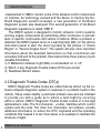
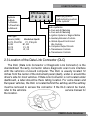
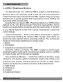
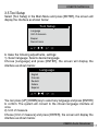
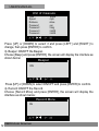
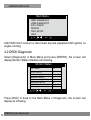
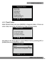
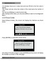
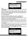
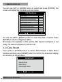
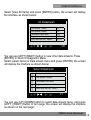
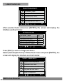
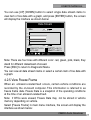
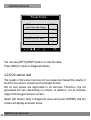
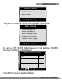
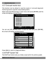
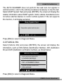
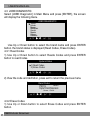
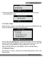
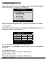
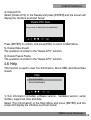
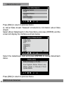
USER’S MANUAL
Table of Contents
1. Safety Precautions and Warnings ..................................................................... 3
2. General Information .......................................................................................... 3
2.1 On-Board Diagnostics (OBD) II ...................................................................... 3
2.2 Diagnostic Trouble Codes (DTCs) .................................................................. 4
2.3 Location of the Data Link Connector (DLC) ................................................... 5
2.4 OBD II Readiness Monitors ............................................................................ 6
2.5 OBD II Monitor Readiness Status ................................................................... 7
2.6 OBD II Definitions ........................................................................................... 8
3. Using the Scan Tool .......................................................................................... 9
3.1 Tool Description .............................................................................................. 9
3.2 Specifications ................................................................................................ 10
3.3 Accessories included .................................................................................... 10
3.4 Power supply ................................................................................................. 10
3.5 Tool setup ...................................................................................................... 11
3.6 Vehicle coverage ........................................................................................... 13
4. Operation ......................................................................................................... 13
4.1 Connection .................................................................................................... 13
4.2 OBDII Diagnostic ........................................................................................... 14
4.2.1 Read Codes ............................................................................................... 15
4.2.2 Erase Codes .............................................................................................. 16
4.2.3 I/M Readiness ............................................................................................ 17
4.2.4 Data Stream ............................................................................................... 18
4.2.5 View Freeze Frame ..................................................................................... 21
4.2.6 O2 sensor test ............................................................................................ 22
4.2.7 On-board monitor test ................................................................................ 24
4.2.8 EVAP System Test ..................................................................................... 25
4.2.9 Vehicle Info ................................................................................................. 25
4.3 JOBD Diagnostic ........................................................................................... 26
4.3.1 Read Codes ............................................................................................... 26
4.3.2 Erase Codes .............................................................................................. 26
4.4 Code lookup .................................................................................................. 27
4.5 Review History .............................................................................................. 27
4.6 Help ............................................................................................................... 29
5. Warranty and Service ...................................................................................... 31
5.1 Limited One Year Warranty ............................................................................ 31
5.2 Service Procedures ....................................................................................... 31
2
OBDII Auto Scanner
USER’S MANUAL
1. Safety Precautions and Warnings
To prevent personal injury or damage to vehicles and/or the scan
tool, read this instruction manual first and observe the following safety
precautions at a minimum whenever working on a vehicle:
1. Always perform automotive testing in a safe environment.
2. Wear safety eye protection that meets ANSI standards.
3. Keep clothing, hair, hands, tools, test equipment, etc. away from all
moving or hot engine parts.
4. Operate the vehicle in a well ventilated work area: Exhaust
gases are poisonous.
5. Put blocks in front of the drive wheels and never leave the
vehicle unattended while running tests.
6. Use extreme caution when working around the ignition coil,
distributor cap, ignition wires and spark plugs. These components
create hazardous voltages when the engine is running.
7. Put the transmission in PARK (for automatic transmission) or
NEUTRAL (for manual transmission) and make sure the parking
brake is engaged.
8. Keep a fire extinguisher suitable for gasoline/chemical/electrical
fires nearby.
9. Don't connect or disconnect any test equipment while the ignition
is on or the engine is running.
10. Keep the scan tool dry, clean, free from oil/water or grease. Use
a mild detergent on a clean cloth to clean the outside of the
scan tool, when necessary.
2. General Information
2.1 On-Board Diagnostics (OBD) II
The first generation of On-Board Diagnostics (called OBD I) was
developed by the California Air Resources Board (ARB) and
OBDII Auto Scanner
3
USER’S MANUAL
implemented in 1988 to monitor some of the emission control components
on vehicles. As technology evolved and the desire to improve the OnBoard Diagnostic system increased, a new generation of On-Board
Diagnostic system was developed. This second generation of On-Board
Diagnostic regulations is called "OBD II".
The OBD II system is designed to monitor emission control systems
and key engine components by performing either continuous or periodic
tests of specific components and vehicle conditions. When a problem is
detected, the OBD II system turns on a warning lamp (MIL) on the vehicle
instrument panel to alert the driver typically by the phrase of "Check
Engine" or "Service Engine Soon". The system will also store important
information about the detected malfunction so that a technician can
accurately find and fix the problem. Here below follow three pieces of such
valuable information:
1). If Malfunction Indicator Light (MIL) is commanded 'on' or 'off';
2). Which, if any, Diagnostic Trouble Codes (DTCs) are stored;
3) Readiness Monitor status.
2.2 Diagnostic Trouble Codes (DTCs)
OBD II Diagnostic Trouble Codes are codes that are stored by the onboard computer diagnostic system in response to a problem found in the
vehicle. These codes identify a particular problem area and are intended
to provide you with a guide as to where a fault might be occurring
within a vehicle. OBD II Diagnostic Trouble Codes consist of a five-digit
alphanumeric code. The first character, a letter, identifies which control
system sets the code. The other four characters, all numbers, provide
additional information on where the DTC originated and the operating
conditions that caused it to set. Here below is an example to illustrate the
structure of digits:
4
OBDII Auto Scanner
USER’S MANUAL
DTC Example
Systems
B=Body
C=Chassis
P=Powertrain
U=Network
Code Type
Generic (SAE):
P0, P2, P34-P39
B0, B3
C0, C3
U0, U3.
P 0 2 0 2
Manufacturer Specific:
P1, P30-p33
B1, B2
C1, C2
U1, U2
Identifying specific
malfunctioning section
of the systems
Sub-systems
1= Fuel and Air Metering
2= Fuel and Air Metering
3= Ignition System or Engine Misfire
4= Auxiliary Emission Controls
5= Vehicle Speed Control and
Idle Controls
6= Computer Output Circuits
7= Transmission Controls
8= Transmission Controls
2.3 Location of the Data Link Connector (DLC)
The DLC (Data Link Connector or Diagnostic Link Connector) is the
standardized 16-cavity connector where diagnostic scan tools interface
with the vehicle's on-board computer. The DLC is usually located 12
inches from the center of the instrument panel (dash), under or around the
driver's side for most vehicles. If Data Link Connector is not located under
dashboard, a label should be there telling location. For some Asian and
European vehicles, the DLC is located behind the ashtray and the ashtray
must be removed to access the connector. If the DLC cannot be found,
refer to the vehicle's
service manual for
the location.
OBDII Auto Scanner
5
USER’S MANUAL
2.4 OBD II Readiness Monitors
An important part of a vehicle's OBD II system is the Readiness
Monitors, which are indicators used to find out if all of the emissions
components have been evaluated by the OBD II system. They are running
periodic tests on specific systems and components to ensure that they are
performing within allowable limits.
Currently, there are eleven OBD II Readiness Monitors (or I/M Monitors)
defined by the U.S. Environmental Protection Agency(EPA). Not all
monitors are supported by all vehicles and the exact number of monitors
in any vehicle depends on the motor vehicle manufacturer's emissions
control strategy.
Continuous Monitors -- Some of the vehicle components or systems
are continuously tested by the vehicle's OBD II system, while others are
tested only under specific vehicle operating conditions. The continuously
monitored components listed below are always ready:
1. Misfire
2. Fuel System
3. Comprehensive Components (CCM)
Once the vehicle is running, the OBD II system is continuously
checking the above components, monitoring key engine sensors, watching
for engine misfire, and monitoring fuel demands.
Non-Continuous Monitors -- Unlike the continuous monitors, many
emissions and engine system components require the vehicle to be
operated under specific conditions before the monitor is ready. These
monitors are termed non-continuous monitors and are listed below:
1). EGR System
2). O2 Sensors
3). Catalyst
4). Evaporative System
6
OBDII Auto Scanner
USER’S MANUAL
5). O2 Sensor Heater
6). Secondary air
7). Heated Catalyst
8). A/C system
2.5 OBD II Monitor Readiness Status
OBD II systems must indicate whether or not the vehicle's PCM's
monitor system has completed testing on each component. Components
that have been tested will be reported as "Ready", or "Complete",
meaning they have been tested by the OBD II system. The purpose
of recording readiness status is to allow inspectors to determine if the
vehicle's OBDII system has tested all the components and/or systems.
The powertrain control module (PCM) sets a monitor to "Ready" or
"Complete" after an appropriate drive cycle has been performed. The
drive cycle that enables a monitor and sets readiness codes to "Ready"
varies for each individual monitor. Once a monitor is set as "Ready" or
"Complete", it will remain in this state. A number of factors, including
erasing of diagnostic trouble codes (DTCs) with a scan tool or a
disconnected battery, can result in Readiness Monitors being set to "Not
Ready". Since the three continuous monitors are constantly evaluating,
they will be reported as "Ready" all of the time. If testing of a particular
supported non-continuous monitor has not been completed, the monitor
status will be reported as "Not Complete" or "Not Ready".
In order for the OBD monitor system to become ready, the vehicle
should be driven under normal operating conditions. These operating
conditions may include a mix of highway driving and stop and go, city type
driving, and at least one overnight-off period. For specific information on
getting your vehicle's OBD monitor system ready, please consult your
vehicle owner's manual.
OBDII Auto Scanner
7
USER’S MANUAL
2.6 OBD II Definitions
Powertrain Control Module (PCM) -- OBDII terminology for the on-board
computer that controls engine and drive train.
Malfunction Indicator Light (MIL) -- Malfunction Indicator Light (Service
Engine Soon, Check Engine) is a term used for the light on the instrument
panel. It is to alert the driver and/or the repair technician that there is a
problem with one or more of vehicle's systems and may cause emissions
to exceed federal standards. If the MIL illuminates with a steady light, it
indicates that a problem has been detected and the vehicle should be
serviced as soon as possible. Under certain conditions, the dashboard
light will blink or flash. This indicates a severe problem and flashing is
intended to discourage vehicle operation. The vehicle onboard diagnostic
system can not turn the MIL off until necessary repairs are completed or
the condition no longer exists.
DTC -- Diagnostic Trouble Codes (DTC) that identify which section of the
emission control system has malfunctioned.
Enabling Criteria --Also termed Enabling Conditions.They are the
vehicle-specific events or conditions that must occur within the engine
before the various monitors will set, or run. Some monitors require the
vehicle to follow a prescribed "drive cycle" routine as part of the enabling
criteria. Drive cycles vary among vehicles and for each monitor in any
particular vehicle.
OBD II Drive Cycle -- A specific mode of vehicle operation that provides
conditions required to set all the readiness monitors applicable to the
vehicle to the "ready" condition. The purpose of completing an OBD II
drive cycle is to force the vehicle to run its onboard diagnostics. Some
form of a drive cycle needs to be performed after DTCs have been erased
from the PCM's memory or after the battery has been disconnected.
Running through a vehicle's complete drive cycle will set the readiness
monitors so that future faults can be detected. Drive cycles vary depending
8
OBDII Auto Scanner
USER’S MANUAL
1. LCD DISPLAY -- Indicates test results.
2. ENTER BUTTON--Confirms a selection (or action) from a menu.
3. ESC BUTTON -- Returns to previous menu.
4/5. UP/DOWN BUTTONs-- Move cursor up or down for selection.
6/7. RIGHT/LEFT BUTTONs -- Move cursor right or left for selection; Or
turn page up or down when more than one page is displayed.
8. USB PORT -- Connects to computer to update the AUTO SCANNER
online.
9. Cable with OBD II CONNECTOR -- Connects the AUTO SCANNER to
the vehicle.
3.2 Specifications
Screen: 2.8"
Input voltage range: 8~32V
Operating temperature: 32_~122
Storage temperature: -4_~158_ / -20_ ~70_ @ RH60%
Outline dimension: 20*8.5*2.8CM
Weight : <17.6 oz (500g)
3.3 Accessories Included
User Manual -- Show the user how to operate the tool.
CD -- Include the software.
USB cable -- Connect to a computer for upgrading online.
3.4 Power supply
The power of the Car scanner is provided via the vehicle Data Link
Connector (DLC). Follow the steps below to power it up:
A. Find DLC on vehicle: A plastic DLC cover may be found for some
vehicles and you need to remove it before plugging the OBDII cable.
B. Plug the connector at the end of OBD II cable to the vehicle.
10
OBDII Auto Scanner
USER’S MANUAL
3.5 Tool Setup
Select [Tool Setup] in the Main Menu and press [ENTER], the screen will
display the interface as shown below:
con.
Tool Setup
Language
Unit of measure
Beeper
Record more
to make the following adjustments, settings:
1). Select language: Selects desired language.
Choose [Language] and press [ENTER], the screen will display the
interface as shown below:
con. Language
English
Francais
Deutsch
Italiano
Espanol
You can press [UP] [DOWN] key to select any language and press [ENTER]
to confirm. The system will convert to the chosen language interface at
once.
2). Unit of measure.
Choose [Unit of measure] and press [ENTER], the screen will display the
interface as shown below:
OBDII Auto Scanner
11
USER’S MANUAL
con.Unit of measure
Flow
Speed
Distance
Pressure 1
Pressure 2
Pressure 3
Pressure 4
lb/min
mph
miles
psi
inHg
inH20
inH20
Press [UP] or [DOWN] to select it and press [LEFT] and [RIGHT] to
change, then press [ENTER] to confirm.
3). Beeper: ON/OFF the Beeper.
Choose [Beep] and press [ENTER], the screen will display the interface as
shown below:
Beeper
con.
ON
Press [UP] or [DOWN] to select ON/OFF and press [ENTER] to confirm.
4). Record: ON/OFF the Record.
Choose [Record More] and press [ENTER], the screen will display the
interface as shown below:
con. Record More
ON
12
OBDII Auto Scanner
USER’S MANUAL
Press [UP] or [DOWN] to select ON/OFF and press [ENTER] to confirm.
When this function is ON, and the icon record Datastream and record
Freeze Frames.
3.6 Vehicle Coverage
This model OBDII/EOBD Scanner is specially designed to work with all
OBD II compliant vehicles, including those equipped with next-generation
protocol -- Control Area Network (CAN). It is required by EPA that all 1996
and newer vehicles (cars and light trucks) sold in the world must be OBD
II compliant and this includes all America, Asian and European vehicles.
A small number of 1994 and 1995 model year gasoline vehicles are
OBD II compliant. To verify if a 1994 or 1995 vehicle is OBD II compliant,
check the Vehicle Emissions Control Information (VECI) Label which is
located under the hood or by the radiator of most vehicles. If the vehicle is
OBD II compliant, the label will designate "OBDII Certified". Additionally,
Government regulations mandate that all OBDII compliant vehicles must
have a "common" sixteen-pin Data Link Connector (DLC).
For your vehicle to be OBD II compliant it must have a 16-pin DLC
(Data Link Connector) under the dash and the Vehicle Emission Control
Information Label must state that the vehicle is OBD II compliant.
4. OPERATION
4.1 Connection
1). Turn the ignition off.
2). Locate the vehicle
3). Plug the OBDII cable into the vehicle
4). Turn the ignition on. Engine can be off or running.
After finishing, press [ENTER] button to enter Main Menu as following
picture:
OBDII Auto Scanner
13
USER’S MANUAL
con. Main Menu
OBDII DIAGNOSTIC
JOBD DIAGNOSTIC
DTC LOOKUP
REVIEW
TOOL SETUP
HELP
CAUTION: Don't connect or disconnect any test equipment with ignition on
engine running.
4.2 OBDII Diagnostic
Select [Diagnostic] in Main Menu and press [ENTER], the screen will
display Monitor Status interface as following.
con. Monitor Status
MIL status
OFF
DTCs in this ECU
Readiness supported
Readiness complete
Readiness not supported
Datastream supported
Ignition
Protocol type
5
6
0
4
20
Spark
VPW
Press [ESC] to back to the Main Menu of Diagnostic, the screen will
display as following.
14
OBDII Auto Scanner
USER’S MANUAL
con. Diagnostic Menu
Read codes
Erase codes
I/M readiness
Data stream
Freeze frame
O2 sensor test
On-Board monitoring
EVAP system test
4.2.1 Read Codes
Select [Read Codes] and press [ENTER] in Diagnostic Menu. If there are
some codes, the screen will display the codes as shown below:
con. Read Codes
Current DTCs ($03)
Pending DTCs($07)
Permanent DTCs($0A)
According to the above figure to select different item by pressing [UP] or
[DOWN] and press [ENTER] to confirm.
con. Current DTC
P0143
1/3
O2 Sensor Circuit Low Voltage Bank 1 Sensor
3
OBDII Auto Scanner
15
USER’S MANUAL
1/3 indicates there are 3 codes total and now P0143 is the first code to
display.
The screen will also show the content of the code below the number of
code.
You can use [ESC]key to view the next code.
After viewing all the codes, you can press [ESC] to return to the Diagnostic
Menu.
4.2.2 Erase Codes
Select [Erase Codes], the screen will display the interface as shown
below:
con. Erase DTC
Clear / Reset Emission-Related
Diagnostic Information, Are you sure?
Press [ENTER] to erase DTC shown below:
con. Erase DTC
Please turn ignition ON with Engine
Off, press ENTER key to continue!
According to the above figure to press [ENTER] and the screen will display
the interface as shown on the next page:
16
OBDII Auto Scanner
USER’S MANUAL
Erase DTC
Emission-Related Diagnostic
Information has been Cleared!
Notes:
Before performing this function, make sure to retrieve and record the
trouble codes.
After clearing, you should retrieve trouble codes once more or turn
ignition on and retrieve codes again. If there are still some trouble codes in
the system, please troubleshoot the code using a factory diagnosis guide,
then clear the code and recheck.
4.2.3 I/M Readiness
I/M refers to Inspection and Maintenance that is legislated by the
Government to meet federal clean-air standards. I/M Readiness
indicates if or not the various emissions-related systems on the vehicle
operating properly and ready for I/M testing.
The purpose of the I/M Readiness Monitor Status is to indicate which of
the vehicle described in Chapter 2.5), and which ones have not yet run
and completed testing and diagnosis of their designated sections of the
vehicle system.
The I/M Readiness Monitor Status function also can be used (after
repair of a fault has been performed) to confirm that the repair has been
performed correctly, and/or to check for Monitor Run Status.
Select [I/M Readiness] and press [ENTER], the screen will display the
interface as shown below:
I/M Readiness
Since DTCs Were Cleared
This Drive Cycle
OBDII Auto Scanner
17
USER’S MANUAL
You can use [UP] or [DOWN] button to select and press [ENTER], the
screen will display the interface as shown below:
con.
I/M Readiness
Misfire monitor
Fuel system monitor
Comprehensive component monitor
Catalyst monitor
Heated catalyst monitor
Evaporative system monitor
Secondary air system monitor
Oxygen sensor monitor
Oxygen sensor heater monitor
EGR and/or VVT sensor monitor
OK
N/A
OK
OK
N/A
OK
N/A
OK
N/A
OK
1/2
You can use [LEFT ] [RIGHT ] button to view other data of vehicle. Press
[ENTER] to return to Diagnostic Menu.
N/A means not available on this vehicle, INC means incomplete or not
ready, OK means Completed or Monitor OK.
4.2.4 Data Stream
Press [UP] or [DOWN] button to select Data Stream in Main Menu
interface and then press [ENTER] button to confirm, the screen will display
the interface as shown below:
Datastream
View All Items
Select Items
View Graphic Items
18
OBDII Auto Scanner
USER’S MANUAL
Select [View All Items] and press [ENTER] button, the screen will display
the interface as shown below:
con.
All Datastream
Fuel system 1 status
Fuel system 2 status
Calculated LOAD value
Engine coolant temperature
Short term fuel trim - bank 4
N/A
N/A
2.0%
-35 C
-36.1%
1/8
You can use [LEFT] [RIGHT] button to view other data streams. Press
[ENTER] to return to Diagnostic Menu.
Select [select Items] in Data stream menu and press [ENTER], the screen
will display the interface as shown below:
con.Select Datastream
[]
[]
[]
[]
[]
Fuel system 1 status
Fuel system 2 status
Calculated LOAD value
Engine coolant temperature
Short term fuel trim - bank 4
1/1
You can use [UP] [DOWN] button to select data stream items, and press
[LEFT ] [RIGHT] button to turn page, the screen will display the interface
as shown on the next page:
OBDII Auto Scanner
19
USER’S MANUAL
con.Select Datastream
[ ]
[√ ]
[ √ ]
[ √]
[ √]
Fuel system 1 status
Fuel system 2 status
Calculated LOAD value
Engine coolant temperature
Short term fuel trim - bank 4
1/1
After selected items and press [ENTER], the screen will display the
interface as shown below:
con. All Datastream
Fuel system 1 status
Fuel system 2 status
Calculated LOAD value
Engine coolant temperature
Short term fuel trim - bank 4
N/A
N/A
2.0%
-35 C
-36.1%
1/8
Press [ESC] to return to Diagnostic Menu.
Select [View Graphic Items] in Data stream menu and press [ENTER], the
screen will display the interface as shown below:
con.Select Datastream
[
[
[
[
[
]
]
]
]
]
Engine coolant temperature
Calculated LOAD value
Short term fuel trim - bank 1
Long term fuel trim - bank 1
Intake air temperature
1/1
20
OBDII Auto Scanner
USER’S MANUAL
You can use [UP] [DOWN] button to select single data stream items to
view item of live data with a graph, and press [ENTER] button, the screen
will display the interface as shown below:
Data Stream
Max
2.0
-35
-96.1 -98.1
2.0
-35
-96.1 -98.1
red
green
pink
black
Min
LOAD-PCT=2.0%
ECT=-35C
SHRTFT1=-96.1%
LONGFT1=-98.1%
Note: There are four lines with different color: red, green, pink, black, they
stand for different datastream choosed.
Press [ESC] to return to Diagnostic Menu.
You can view all data stream items or select a certain item of live data with
a graph.
4.2.5 View Freeze Frame
When an emission-related fault occurs, certain vehicle conditions are
recorded by the on-board computer. This information is referred to as
freeze frame data. Freeze Data is a snapshot of the operating conditions
at the time of an emission-related fault.
Note: if DTCs were erased, Freeze Data may not be stored in vehicle
memory depending on vehicle.
Select [Freeze Frame] in main menu interface, the screen will display the
interface as shown below:
OBDII Auto Scanner
21
USER’S MANUAL
con.
Freeze Frame
DTC that caused required
freeze frame data storage
Short term fuel trim - bank 1
B3376
Short term fuel trim - bank 3
71.1%
16.4%
Long term fuel trim - bank 1
0.0%
Long term fuel trim - bank 3
64.1%
1/5
You can use [LEFT] [RIGHT] button to view the data.
Press [ESC] to return to Diagnostic Menu.
4.2.6 O2 sensor test
The results of O2 sensor test are not live values but instead the results of
the ECU live sensor screens such as Graph Screen.
Not all test values are applicable to all vehicles. Therefore, the list
generated will vary depending on vehicle. In addition, not all vehicles
support the Oxygen Sensors screen.
Select [O2 Sensor Test] in Diagnostic menu and press [ENTER] and the
screen will display as shown below
22
OBDII Auto Scanner
USER’S MANUAL
con. Select O2 Sensor
Bank1-Sensor1
Bank1-Sensor2
Press [ENTER] button, the screen will display as shown below:
con. Bank1-Sensor2
Rich to lean sensor(V)
Lean to rich sensor(V)
Rich to lean sensor time
Minimum sensor voltage
Maximum sensor voltage
You can use [UP] [DOWN] button to select an item and press [ENTER],
the screen will display as shown below:
con. Rich to lean sensor(V)
Test ID
$01
Test value
0.664V
Minimum limit
0.664V
Maximum limit
0.000
Status
Pass
Press [ESC] to return to Diagnostic Menu.
OBDII Auto Scanner
23
USER’S MANUAL
4.2.7 On-board monitor test
This function can be utilized to read the results of on-board diagnostic
monitoring tests for specific components/systems.
Select [On-board Monitoring] in main menu and press [ENTER] and the
screen will display as shown below:
con.On-Board Monitoring
Test $02 date
Test $03 date
Test $05 date
Test $08 date
Test $09 date
Test $0B date
Test $0C date
Test $12 date
1/2
You can use [UP] [DOWN] button to select an item and press [ENTER],
the screen will display as shown below:
Test $02 Data
Component ID
$5e
Limit type
Max
Test value
33733
Minimum limit
-----
Maximum limit
39982
Status
Pass
Press [ESC] to return to Diagnostic Menu.
4.2.8 EVAP System Test
The EVAP test function lets you initiate a leak test for the vehicle system.
24
OBDII Auto Scanner
USER’S MANUAL
The AUTO SCANNER does not perform the leak test, but signals to
vehicle function, refer to the vehicle procedures necessary to stop the test.
Select [EVAP System Test] and press [ENTER], the screen will display the
relative information about EVAP system. Some vehicle manufacturers do
not allow external devices to control vehicle system. If the car supports
this function, it will display as below:
con. Evap System Test
Evaporative system leak test pass
Press [ESC] to return to Diagnostic Menu.
4.2.9 Vehicle Info
Select [Vehicle Info] and press [ENTER], the screen will display the
information, such as VIN (Vehicle identification Number), CID (Calibration
ID) and CVN (Calibration verification number), as shown below:
con. Vehicle Information
Vehicle Identification Number(VIN):
LCGJD52E76H238345
Calibration Identifications(CID):
CID1: JC7BJEMNK314284K
Calibration Verification Number(VIN):
CVN: AJ234HX
Press [ESC] to return to Diagnostic Menu.
OBDII Auto Scanner
25
USER’S MANUAL
4.3 JOBD DIAGNOSTIC
Select [JOBD Diagnostic] in Main Menu and press [ENTER], the screen
will display the following menu.
Toyota
Honda
Nissan
Mitsubishi
Suzuki
Mazda
Subaru
Daihatsu
JOBD DIAGNOSTIC
Use Up or Down button to select the brand name and press ENTER
button. the brand status is displayed (Read Codes, Erase Codes).
4.3.1 Read Codes
1) Use Up or Down button to select Reade Codes and press ENTER
button to read Codes.
System Status
1) Read Codes
2) Erase Codes
2) View the code and definition, press exit to return the previous menu
Read$11Codes
Pd
1/6
Generic
P0115
======================
Engine Coolant Temperature
Sensor 1 Circuit
4.3.2 Erase Codes
1) Use Up or Down button to select Erase Codes and press ENTER
button.
26
OBDII Auto Scanner
USER’S MANUAL
System Status
1) Read Codes
2) Erase Codes
2) Press enter button to erase the codes and return to previous menu;
press exit button to exit.
Erase Fault Codes
Are you sure?
4.4 Code Lookup
Select [Code Lookup] in the Main Menu and press [ENTER] and the
screen will display the interface as shown below
con. DTC Lookup
Please input DTC:
P0000
Time 1st range: P, C, B, U
Time 2rd range: 0, 1, 2, 3
The others from 0 to F
You can use [UP] [DOWN] key to change the first letter. It can be switched
among. Press [LEFT] [RIGHT] key to input number. After you input the
code number, press [ENTER] to view the definition of the code.
After viewing the definition, press [ESC] to return to the Main Menu.
4.5 Review History
This function is used to review the recorded Data Streams, DTC, and
Freeze Frame.
OBDII Auto Scanner
27
USER’S MANUAL
Select [Review History] in the Main Menu and press [ENTER] and the
screen will display the interface as shown below:
con. Review History
Review DTC
Review Datastream
Review Freeze Frame
Delete DTC Data
Delete Datastream
Delete Freeze Frame
CAUTION: About the record function, please view the chapter Tool Setup
1). Review DTC
Select [Review DTC] in the Review and press [ENTER] and the screen will
display the interface as shown below:
con. Review DTC
Date & Time
2010-05-10(18:42:05)
LCGJD52E76H238456
2010-05-10(18:42:05)
LCGJD54S74Q236546
DTC No.
18
DTC Type
Current
18
Pending
The recorded DTC will be displayed as shown above.
You can use [UP] [DOWN] key and press [ENTER] button to view detailed
information,
2). Review Data stream
The operation is similar to the "Review DTC" function.
3). Review Freeze Frame
The operation is similar to the "Review DTC" function.
28
OBDII Auto Scanner
USER’S MANUAL
4). Delete DTC
Select [Delete DTC] in the Review and press [ENTER] and the screen will
display the interface as shown below:
con. Delete DTC Data
Are you sure to delete the recorded data ?
Press [ENTER] to confirm, and press [ESC] to return to Main Menu.
5). Delete Data stream
The operation is similar to the "Delete DTC" function.
6). Delete Freeze Frame
The operation is similar to the "Delete DTC" function.
4.6 Help
This function is used to view Tool Information, About OBD, and About Data
stream.
con. Help
Tool Information
About Datastream
1).Tool Information includes: software version, hardware version, serial
number, supported, time and date.
Select [Tool Information] in the Help Menu and press [ENTER] and the
screen will display the interface as shown below:
OBDII Auto Scanner
29
USER’S MANUAL
con.
Tool Information
Software Version
V1.21
Hardware Version
V1.03
Serial Number
DT111249050
Press [ESC] to return to previous menu.
2). About Data stream: Relevant introductions information about Data
stream.
Select [About Datastream] in the Help Menu and press [ENTER] and the
screen will display the interface as shown below:
con.
About Datastream
FUEL SYS
LOAD_PCT
ECT
SHIRTFTX
LONGFTX
FRP
MAP
RPM
1/7
Select the datastream item and press [ENTER] to review datastream
status.
con. FUEL SYS
FUEL SYS(Open or CLSD)
Fuel System Status Show Loop
Status (Open or Closed) of Fuel
System Banks.
Press [ESC] to return to previous menu.
30
OBDII Auto Scanner
USER’S MANUAL
5. Warranty and Service
5.1 Limited One Year Warranty
We warrants to its customers that this product will be free from all
defects in materials and workmanship for a period of one (1) year from the
date of the original purchase, subject to the following terms and conditions:
1). The sole responsibility of us under the Warranty is limited to either
the repair or, at the option of us, replacement of the scan tool at no charge
with Proof of Purchase. The sales receipt may be used for this purpose.
2). This warranty does not apply to damages caused by improper use,
accident, flood, lightning, or if the product was altered or repaired by
anyone other than the Manufacturer's Service Center.
3). We shall not be liable for any incidental or consequential damages
arising from the use, misuse, or mounting of the scan tool. Some states do
not allow limitations on how long an implied warranty lasts, so the above
limitations may not apply to you.
4). All information in this manual is based on the latest information
available at the time of publication and no warranty can be made for its
accuracy or completeness. We reserves the right to make changes at any
time without notice.
5.2 Service Procedures
If you have any questions, please contact your local store, distributor
or visit our website.
If it becomes necessary to return the scan tool for repair, contact your
local distributor for more information.
OBDII Auto Scanner
31