1
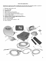
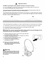
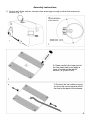
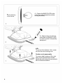
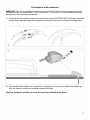
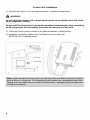
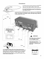
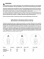
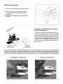
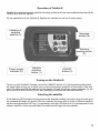
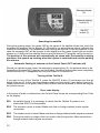
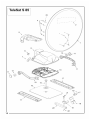
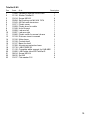
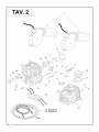
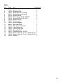
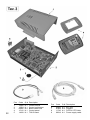
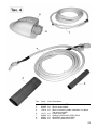
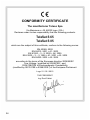
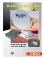
Installation guide
and user manual
GB
TELECO WARRANTY
Teleco guarantees its satellite dishes and terrestrial antennas against any
material and/or construction fault and defect. The warranty offered by
TELECO is limited to the free-of-charge replacement or repairing of any
parts that are deemed faulty by TELECO. The warranty is applicable for a
period of 3 YEARS starting from the product purchase date; however, it will
only be considered valid if the Customer is able to produce a written document
(invoice or tax receipt) showing the purchase date.
The following is excluded from the TELECO warranty:
a. Damages caused by incorrect installation and/or use and/or maintenance
b. Damages resulting from product alterations not authorised by Teleco
c. Damages resulting from the use of spare parts different from original
Teleco parts
d. Damages resulting from repairs carried out by personnel not
authorised by Teleco
e. Normal part wear;
f. Expenses incurred for spare parts transport between the Customer's
and the service centre
g. Damages that may occur during transport:
the Customer shall always be responsible for transport risks.
Information
Congratulations on your purchase! TeleSat S is among the most technologically advanced
products in the field of satellite TV reception. This handbook has been prepared to provide
information on how to install, use, maintain and technical specifications your TeleSat S.
For additional information, please contact your local dealer or directly the manufacturers:
TELECO s.p.a.
Via E. Majorana 49
48022 LUGO (RA)
Web site: www.telecogroup.com
Technical attendance: 899.899.856
TELECO .p.a. declines all responsibility for any errors contained in this manual. All the
contained information are up to the dates of printing and of the above-mentioned software
revisions. TELECO .p.a. reserves the right to introduce any modification made necessary by
the development of its products.
1
TABLE OF CONTENTS
Page
Information.............................................................................................................................1
List of accessories .................................................................................................................3
Installation of dish on motor unit............................................................................................4
Outside Unit Installation .........................................................................................................7
Control Unit Installation..........................................................................................................8
Connections...........................................................................................................................9
LNB rotation.........................................................................................................................10
Tips on the best use of TeleSat S ........................................................................................12
Operation of TeleSat S.........................................................................................................13
Troubleshooting ...................................................................................................................15
Technical specifications .......................................................................................................15
Spare Parts Table ................................................................................................................16
Recycling: with a view to reducing disposal of waste electrical and electronic
equipment as much as possible, do not throw out this end of life appliance together
with other unsorted municipal waste, but make use of a recycling centre.
2
List of accessories
TeleSat S is delivered inside a cardboard case that has been specially made to protect it
from knocks and pressure. The following accessories are supplied:
1
2
3
4
5
6
7
8
9
10
11
12
13
14
External motor-driven unit
65 - 85 cm dish
Universal LNB
Control unit
Wall-mounted control panel
Motor connecting cable extension
Coaxial cable extension for antenna signal
Power Supply Cable
Control unit/control panel connection cable
Waterproof box to pass leads through to interior
Heat-shrinking sheaths
No. 4 Locknuts M6
No. 4 Screws and Locknuts – M6
User’s manual
3
Important notice
TeleSat S is packaged in two separate cartons for transport reasons:
a) the first package contains the driving unit with all the cables, and the Control unit.
b) the second package only contains the dish.
• It is important to check that the dish has not been damaged during transport when the
package is opened. In particular, check the following well:
• By resting the dish edge against a flat surface (e.g. the floor or a wall) check that it makes
contact to the surface all around. If it is not so, try and make the edge level, without denting
the dish, or call our After-Sales Service.
YES
NO
• After checking that everything is in order, install the dish on the driving unit as follows:
1) Temporarily connect the Control unit to the driving unit through the grey motor cable.
2) Connect the Control panel to the Control unit through the RJ45 cable.
3) Power the Control unit using a battery.
Warning: For correct connection of the wiring and to prevent damage to the
equipment please consult page 9 “Connections”.
4) Press the switch-on button on the control panel and wait
for the dish support mast to rise.
5) Once the desired position has been reached, turn off the
TeleSat S via the same button.
6) Secure the dish to the mast and screw
down the four supplied screws.
7) Turn the unit on again and wait for
the antenna to close.
8) Disconnect the the Control unit,
the battery and install the driving
unit on the vehicle
Warning:
NEVER loosen the two dish arm lock
screws (A) to attach the dish as this
will result in loss of alignment with
the antenna.
4
Assembly instructions
1) On the roof of the vehicle, choose a free area large enough to allow the antenna to
revolve (Fig. 2).
Driving direction
of the vehicle
TeleSat S S65 - 110 cm
TeleSat S S85 - 150 cm
2) Clean carefully the lower part of
the two base plates and apply a
layer of binder on the whole
surface. (e.g SIKAFLEX)
3) Position the two cables coming
out from the centre towards either
the front or the back of the antenna.
5
Driving direction
of the vehicle
4) Fasten the BASE PLATE to the
roof (short side towards the vehicle
driving direction),
5) Apply a layer of silicone
all around the BASE PLATE
in order to make it completely
waterproof
N.B.:
To service the Outdoor Unit, screw
out the four self-locking nuts.
Outdoor unit reassembly
To ensure tight locking of the nuts
and prevent possible pin breaks:
tighten the nuts using a torque wrench
set to 8 Newtons/metre
6
Connection with extension
WARNING The Grey and Black cables coming out of the Outside Unit are generally long
enough to allow for connection to the Control unit. If it is not so, use the extension cables
and perform the following operations:
1) Connect the two cables coming from the centre of the OUTSIDE UNIT to the two supplied
extensions, waterproofing the connectors using the two pieces of heat-shrinking tube.
2) Accomodate the cables into a protection raceway up to the point where the cables go
into the vehicle, using the suitable supplied fairlead.
Seal the fairlead carefully so as to prevent any infiltration by water
7
Control Unit Installation
1) Position the Control unit in an easy accessible, ventilated compartment.
WARNING:
Do not install the Control unit in areas where liquids can be spilled, since this could
cause irreparable damage.
Do not install the Control unit in very small, unventilated compartments, since overheating
could compromise its functionality and render the warranty null and void.
2) Place the Control panel comando in an easily accessible, visible position.
3) Install the connection cables (Grey and Black) until you reach the
OUTSIDE UNIT installation area.
Control unit
Control Panel
Note: Install the wall-mounted control unit with the (Grey and Black) connection cables
bent as shown in the picture. This installation tip will prevent any condensation water from
flowing down the cables into your control unit electronics - damaging it beyond repair and
voiding your warranty.
8
Connections
1) Connect the grey cable (motors) to the MOTOR
UNIT connector and the Black coaxial cable
(antenna) to the LNB connector of the Control unit.
2) Connect the Receiver or the TV with Receiver
to the SAT RECEIVER connector. You can connect
any satellite receiver.
3) Connect directly the BLACK cable of the Control unit to the NEGATIVE
POLE of the vehicle 12 Volt Battery, and the RED cable to the POSITIVE
POLE + (remember not to mix the + and - poles up), using 2 cables of
a cross section of 2.5 mm².
Black
Grey
Sat Receiver or
Television with Sat
Receiver
not supplied
WARNING:
The 3-way power connector (P)
must only be inserted in the
12 Vdc POWER socket.
Grey
Inserting this connector in any
other socket will cause
irreparable damage to the board
and render the warranty null
and void.
Green
4) The GREEN safety cable of the Control Unit must be
connected to the consensus of the vehicle startup console (in
many cases such consensus is located on Pin 15 in the main
terminal board). In this way, whenever the motor is started,
this cable receives a positive + 12 Vdc voltage, which will
automatically lower the antenna and lock all functions of the
Control Unit simultaneously.
9
WARNING
This technical note is to call the attention of the installation personnel to certain details
of TeleSat S installation. During installation, you must take the following precautions:
The power supply cable must directly come from the battery and must have no junctions.
Minimum cross section of the cable is 2,5 mm2. For cable lengths equal to or above 6 metres,
the minimum cross-section is 4 mm2. Only the TeleSat S must be connected to this cable;
all the other devices must be connected to another power supply cable.
The cable connecting the driving unit to the TeleSat S Control unit must NEVER be cut for
any reason whatsoever: should the cable turn out to be too long, wind the extra part into a
coil in a free area of the vehicle. Leave a little cable in the driving unit area; should any
technical operation be required, it will make it easier to remove the driving unit.
Failure to observe these instructions shall render the Warranty null and void.
LNB rotation for ideal signal reception in extreme
(South-western or South-eastern) areas in Europe
Please be reminded that your outside low-noise block converter (LNB) has its own special
mounting position that must be maintained, otherwise you will be unable to receive any
signals. The LNB pre-defined installation position is along the dish centre line (Fig. A): in this
configuration, the TeleSat S System will operate correctly in most European countries. If,
however, you happen to find yourselves very far from the orbital position of your required
satellite, you may want to adjust your low-noise block converter angle. This is especially true
if you wish to receive satellite signals from Astra 19E, Astra 28E or HotBird 13E and you are
in Portugal or Morocco: you will then have to adjust the LNB angle as shown in fig. B, while
if you happen to be in Turkey, to receive signals from the same satellites you will have to
adjust your LNB to the position shown in fig. C.
Place
Position
HotBird 13E
Astra 19E
Astra 28E
Lisbona
Casablanca
Ankara
B
B
C
25°
27°
22°
28°
34°
15°
37°
41°
5°
10
LNB tilt adjustment
1) Loosen the LNB U-bolt locking screws
2) Turn in either the Clockwise (West)
or the Anti-clockwise (South-East)
direction
3) Lock the LNB again with the special
screws
Important information for proper
antenna tracking
1) Before performing antenna tracking
operation, make sure you have positioned
your vehicle so that the view towards the
South (where Satellite signals come from)
is free from any nearby obstacle (trees,
houses, etc.). This way, the antenna will
be free to receive signals coming from
the satellite.
WRONG
POSITION
RIGHT
POSITION
2) It is also important to know that satellites do not transmit with the same intensity throughout
Europe, so if you are outside the reception area, your TeleSat S search might be unsuccessful.
The reception areas for each Satellite can be found on the main magazines dealing in this
line of business. Also remember that the larger the dish, the more reception area is available.
WRONG POSITION
RIGHT POSITION
11
Tips on the best use of TeleSat S
When you park your vehicle, make sure that:
1) No obstacle (for example trees) is too near your antenna, preventing it from moving
freely. No metal or glass wall is very near (about 5 m) the antenna, since this would
act as a mirror for satellite signals and could induce the antenna to stop towards it.
2) Remove any snow or ice from the TeleSat S before actuating it in order to avoid
wasting battery power trying to lift it.
3) If you decide to turn the engine of your vehicle on in order to re-charge its batteries,
with the safety cable connected to the ignition key, the antenna, if lifted, will come
down automatically and it will not be possible to lift it again as long as the engine is
running.
4) Make sure that your batteries are always sufficiently charged, since, if the voltage
falls below 10 Volts, the TeleSat S electronic safety circuit will prevent the
antenna from rising.
5) Should you use 12 Volt power supply instead of batteries, be careful to use stabilized
power supply being able to provide 5 A continuously and at least 10 A for short periods.
At all costs, avoid using low quality, non stabilized battery chargers.
6) It is recommended not to use the antenna under strong wind conditions
(80 km/h). Failure to comply with this condition may result in product degradation
which the manufacturer cannot be held responsible for.
7) Antenna closing operations, whether by user's control or automatically for
vehicle start-up, require variable time.
Before starting the vehicle, always make sure that the antenna is fully closed.
*
12
The manufacturer declines any liability for all degradations suffered by the
product owing to misuse.
Operation of TeleSat S
TeleSat S is a fully automatic satellite tracking system and can track satellites that emit both
DVB-S and DVB-S2 signals.
All the operations of the TeleSat S System are carried out via the Control panel.
Indicator of
selected
satellite (5)
Message
display (4)
Antenna
parking button
(2)
Power supply
indicator (6)
Satellite
selection
button (1)
ON/OFF
button (3)
Turning on the TeleSat S
To turn on the TeleSat S System, press the ON/OFF button (3). Upon pressing the button,
all signal lights will go on to allow you to check the proper operation of the board. After this
step, the message ON will appear on the display (4), the red power supply indicator (6) will
go on and one of the LEDs (5) will start flashing to indicate the selected satellite,
Selecting the satellite
If the flashing LED already corresponds to the desired satellite just wait a few seconds and
the antenna will begin its search. Should, instead, the user wish to track a different satellite,
he/she must press the SAT key (1) repeatedly until the LED that is on (5) corresponds to the
chosen satellite. A few seconds later the antenna will begin the new search.
13
Message display
(4)
Antenna parking
button (2)
ON/OFF
button (3)
Searching the satellite
During the seeking stage, the green LED by the name of the satellite blinks fast, while the
message ON appears on the display (4) followed by an animated bar which indicates the
rotation of the antenna. The antenna will stop moving as soon as it finds the satellite; in this
case the message SAT will be brought to the display and the green signal light will remain
always on. At this point the satellite receiver and the desired TV program can be turned on.
The position of the antenna will automatically be saved after first satellite tracking
operation: this speeds up tracking when the system is switched back on after parking
the antenna.
Automatic Parking of antenna via the Control Panel (OFF indicator off)
Should you decide to park (stow) the antenna by pressing key (2), the antenna starts to be
lowered and the word OFF appears on the Display. Once the antenna has been completely
closed the word OFF disappears and only the Power LED remains on.
Turning off the TeleSat S
If you wish to turn off the TeleSat S, press the ON/OFF button (3) and make sure that all
signal lights are off. In this case the antenna remains in the position it was before turning off.
Proper connection of the green safety cable ensures that the antenna is closed as long as
the vehicle moves.
Error code display
In the event of faults or malfunctions, the Control Panel shows the corresponding Error Code
on the display:
ER1
No satellite found. It is necessary to check that the TeleSat S system is not
obstructed SOUTH of the satellite.
ER2
The elevation motor is locked. Make sure that no foreign matters hinder regular
movement
ER3
The rotation motor is locked. Make sure that no foreign matters hinder regular movement
ER9
During the switch-on stage a fault occurred in the driving motor. Make sure that no
foreign matters hinder regular movement.
14
Troubleshooting
• If the TeleSat S has not found the satellite after a complete search, check the following:
a) Is the view towards the South free from any obstacle?
b) Is the place you are at within the reception area of the satellite you have chosen?
c) Is the cable connecting the LNB to the antenna firmly fastened?
It could have been ripped off or come loose because of contact with an unexpected
obstacle.
d) Are all the connections on the Control unit properly set up?
• If the antenna has stopped after performing tracking, but neither messages nor images
appear on the screen:
a) Have you switched your receiver on ?
b) Have you switched your TV set on ?
c) Have you selected the right satellite ? Make sure that the services you wish to receive
are really available on the required satellite.
• If the Control panel does not turn on when you press the ON/OFF button, check the
following:
a) Is the engine of your vehicle running? Turn it off, since this means the safety system
which keeps the antenna down is operating.
b) Is the battery charged?
c) Is the fuse on the power lead intact? Replace it with a 5A one of the same type.
Technical specifications
SPECIFICATIONS
Search system
Fully automatic, NID recognition according to the
DVB-SI EN 300 468 specifications with DVBS2 tuner.
Satellites which can be set
Extensions
7
USB 1.0 Port
Control panel
MISCELLANEA
Power supply
Absorbed current
Current in stand-by
Fuse
Dimensions
Weight
(outside driving unit)
12 Vdc ( 10 - 15 Vdc )
5 A max.
< 5 mA
5A
160 x 187 x 58 mm (Control unit)
120 x 35 x 80 mm (Control panel)
~ 1 kg (Control unit and Control panel)
TeleSat S65: ~ 9 kg.
TeleSat S85: ~ 10,6 kg
15
16
TeleSat S 65
Pos
Code
Q.tà
1
2
3
4
5
6
7
8
9
10
11
13
14
15
16
17
18
19
20
21
22
23
10487
15116
08595
03685
12544
12571
12859
11008
12858
12857
12860
12319
12316
12318
12317
12320
15718
13110
12679
09014
09015
15616
Parabolic antenna D=650 mm
Sticker TeleSat S
Screw M5X14
Self-locking nut M5 UNI 7474
65 Dish arm aluminium
Plastic cover
Plastic door for cable
Hole Gromet
Lnb arm left
Lnb arm right
Plastic cover for screw lnb arm
Dish arm insert in zamak
Motor base
Central shaft
Base for shaft
Aluminium protection base
LNB STARK S1
Complete white support for LNB ABS
LNB holder tube 650 TeleSat S
Screw M5X14
Sut M5
Flat washer D 5
Description
1
1
4
4
1
1
1
1
1
1
2
2
1
1
1
2
1
1
1
2
2
4
17
18
TeleSat S 85
Pos
Code
Q.tà
Description
1
2
3
4
5
6
7
8
9
10
11
13
14
15
16
17
18
19
20
21
22
23
10488
15116
15614
03684
12543
12571
12859
11008
12858
12857
12860
12319
12316
12318
12317
12320
15718
13110
12680
09014
09015
15617
Parabolic antenna D=850 mm
Sticker TeleSat S
Screw M6X16
Self-locking nut M6 UNI 7474
85 Dish arm aluminium
Plastic cover
Plastic door for cable
Hole Gromet
Lnb arm left
Lnb arm right
Plastic cover for screw lnb arm
Dish arm insert in zamak
Motor base
Central shaft
Base for shaft
Aluminium protection base
LNB STARK S1
Complete white support for LNB ABS
LNB holder tube 850 TeleSat S
Screw M5X14
Sut M5
Flat washer D 6
1
1
4
4
1
1
1
1
1
1
2
2
1
1
1
2
1
1
1
2
2
4
19
20
TAV 2
Pos
Code
Q.tà
Description
1
2
3
4
5
6
7
8
9
10
11
12
13
14
15
16
17
18
19
11161
12322
12321
12671
07503
03685
13434
12856
12570
12569
09241
13130
12862
12861
13503
12616
13568
14749
16424
Electric motor
Rotating slider
Switch pusher in zamak
Waterproof microswitch
Screw M5x60
Self-locking nut M5 UNI7474
Screw M10X40 UNI 5931
Brass bushing
Vertical gear
Horizontal gear
Spring pin 3x20
Spring for commutator
Lnb bushing left
Lnb bushing right
Spring washer
Connector strip T0074D
Motor Cable Kit 2,5 mt ( TeleSat S 65 )
Motor Cable Kit 2,5 mt ( TeleSat S 85 )
Washer
2
2
1
2
2
2
2
1
1
1
2
1
1
1
2
1
1
1
2
21
22
Pos
Code
Q.tà Description
1
2
3
4
5
15056
15054
09835
15112
14918
N.1
N.1
N.4
N.1
N.1
Control unit lid
Control unit bottom
Black rubber foot
Control panel
T0215 board
Pos
Code
Q.tà Description
6
7
8
9
02203
01458
11742
09318
N.1
N.4
N.1
N.1
4A Fuse
Support
PATCH UTP Cable
Power supply cable
Pos
Code
Q.tà Description
1
2
3
4
05950
03598
03597
13018
N.1
N.1
N.1
N.1
6
7
8
9
13171
06900
06901
06898
N.1
N.1
N.1
N.1
3 m coax cable F/F.connector
Shrink-wrap sheath
Shrink-wrap sheath
Motor connecting cable extension 2+8 poles
3mt with connector
Cable cover abs
Gasket O-SEALING VITON PG21
SKINTOP cable gland PG21
SKINTOP plastic nut PG21
23
CONFORMITY CERTIFICATE
The manifacturer Teleco Spa
Via Majorana nr. 49, 48022 Lugo ( RA )
Declares under its own responsibility that the following products:
TeleSat S 65
TeleSat S 85
which are the subject of this certificate, conform to the following norms:
EN 60065: 2002
EN 55013: 2001 + A1: 2003
EN 61000 – 3 - 2: 2000 + A2: 2005
EN 61000 – 3 – 3: 1995 + A1: 2001 + A2: 2005
EN 55020: 2002 + A2: 2005
according to the terms of the European directive 2006/95/EC
Low Voltage ( modified by 93/68/CEE ) and
2004/108/CEE of Electromagnetic Compatibility
(modified by 92/31/CEE e 93/68/CEE ) of the European Parliament.
Lugo 21 / 05 / 2015
THE PRESIDENT
Ing. Raul Fabbri
24
26_06_15