1
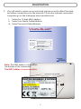
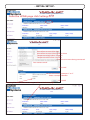
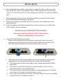
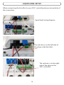
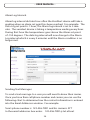
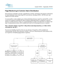
INSTALLATION / SETUP GUIDE & USER MANUAL (Gen 2) Custom www.custombiogenics.com BioGenic 74100 Van Dyke Road w Bruce Twp., MI 48065 w USA Systems 1.800.523.0072 w Tel: 1.586.331.2600 w Fax: 1.586.331.2588 - TABLE OF CONTENTS VersAlert Parts List - Page 1 VersAlert Registration - Pages 2, 3 VersAlert Initial Set Up - Pages 4 - 8 VersAlert Liquid Level Set Up - Pages 9, 10 VersAlert Product Identification - Page 11 Voltage & Current Settings - Page 12 Operations Manual - Pages 13 - 21 - SPECIFICATIONS Your VersAlert is intended to operate in the following environment: Indoor use only Installation category II per IEC664 Pollution Degree Level II per IEC61010-1 Temperature: 5°C to 40°C operating per IEC61010-1 Humidity: Maximum relative humidity 80% for temperatures up to 31°C decreasing linearly to 50% relative humidity at 40°C VersAlert Power Requirements: 6 V DC Plug In or Lithium ION Battery. Only use battery provided by Custom BioGenic Systems. Power requirements: 6V DC Power Connection Dimensions (L x W x H): 5 1/2” x 5 1/4” x 1 3/4” or 13.9 cm x 13.33 cm x 4.44 cm Weight: 11.65 oz. or 0.33303 kg (including battery) For additional information regarding Voltage and Current settings please contact Custom BioGenic Systems Customer Service. For Technical Assistance Call: 1.800.523.0072 (U.S. Only) Phone: 586.331.2600 Fax: 586.331.2588 www.custombiogenics.com - PARTS LIST 1. Open box and become familiar with components: #1. Transmitter (qty. 1) 12 digit MAC address (located on the bottom of the transmitter) #2. 8’ temperature probe (qty. 1) #3. Ethernet cable (qty. 1) (you must use the supplied cable) #4. Power Supply and connection adaptors (the power supply automatically adjusts to 100-240v AC, 50-60hz .3amps). Velcro tabs 1 - REGISTRATION 2. You will need to create an account and register your VersAlert Transmitter before connecting it to the network. From your internet connected computer go to the web page www.versalert.com i. Enter the 12 digit MAC address ii. Enter User Name: DefaultAdmin iii. Enter Password: DefaultAdmin VERSALERT MAC Address: XXXXXXXXXXXX Username: DefaultAdmin Password: DefaultAdmin Remember my MAC address Custom BioGenic Systems Note: The MAC address is located on the bottom of the transmitter. The MAC address is case sensitive. MAC ADDRESS: XXXXXXXXXXXX 2 - REGISTRATION 3. You will now see the Create Your Account page. Fill in the information requested. When naming the device it should represent the equipment being monitored as this name will be used in email notifications to identify the equipment that is in alarm condition. The email address you enter will be the default contact. This information can be changed later. Custom ® BioGenic Systems Create your account Device MAC: Name your device: 00394184E1D XYZ LAB FREEZER 3 Name your device (5 characters minimum) Name ( 5 characters minimum) Science Centeryour Inc. device Company name (5 characters minimum) Company name (Address 5 characters minimum) 437 Science Center Dr. Account Name (Compnay Name): Address 1: Address 2: Address City: Address Your Town Address 93970 Address Address USA Address Name of contact Kevin Address Name of contact Smith Must be valid email address [email protected] Dr. Smith Name of contact Enter username (8 characters minimum) xyz93970 Enter password Name of contact Repeat password ******** State: Zip Code: Country: Primary Contact First Name: Primary Contact Last Name: Primary Email: Primary Username: Account Password: Repeat Password: Must be a valid Email address User name Enter password ( 8 characters minimum) Repeat password Submit Click submit Click submit Note: Username and password ARE case sensitive Now that your account is created, for future logins you will log in with the username and password you just entered. You do not need to enter the MAC Address in subsequent logins. 3 - INITIAL SET UP - From the HOME page click Settings How often to record the data How often to record data when in alarm Temperature high alarm set point Temperature low alarm set point Enter the time zone being monitored Your contact email Click SAVE Set the unit of measurement °C or °F Enter a custom identifier Click SAVE Choosing Yes will make these settings visible on the home page 4 - INITIAL SET UP 4. Mounting the Transmitter: Using the 4 (supplied) Velcro tabs securely mount the VersAlert Transmitter either on the equipment to be monitored or in a location close to the equipment. Please consider the following: i. The temperature probe wire should be able to reach the Transmitter from the equipment being monitored. ii. The power supply should be able to reach the Transmitter from the power outlet. iii. The Transmitter should be mounted in a place where it is visible and within reach of the operator. Connect your VersAlert Transmitter You must register each VersAlert Transmitter before making these connections 5. Connect the Temperature probe. i. Remove the temperature probe from the bag. Insert the male connector on the probe wire into the VersAlert Transmitter. Note that the male connector can be inserted only one way. ii. The other end of the Temperature probe should be secured in the equipment to be monitored. Please consider the following. a. The placement of the probe affects the temperature that will be reported. b. The probe should be placed in a location that is close to the inventory that you are monitoring. c. You may need to thread the probe into the equipment. It should not come in to contact with the heat source. d. The probe should be secured in a manner that it cannot accidently moved from its installed location. 5 - INITIAL SET UP - 6.Connect the Ethernet Cable (provided) to the Ethernet 1 port. Connect the end marked network to your network to Ethernet / Internet Port. Depending on your network setup you can either plug the end of the cable marked Network into an Ethernet Port / Internet Connection on the wall (fig 1) or connect the cable directly to your internet router (fig 2). fig 1 fig 2 6 - INITIAL SET UP 7. Connect the power supply (provided) to your wall outlet. The power supply automatically adjusts between 110v and 240v. (you may need to use the supplied adapter to connect to your wall outlet) 8. When you see 4 blue lights on the front of the device (this may take several minutes). 9. Pull the tab labeled “PULL TO ENABLE BATTERY BACKUP” completely out of the device. This will engage the backup battery. 7 - INITIAL SET UP - When the VersAlert is working properly you will see 4 blue lights on the front of the device Periodically, you will see the Tx and Rx lights blink, this means the device is transmitting and receiving information. You may also see the red battery status light on. This indicates the battery is charging. Once the battery is charged the light will go off. A flashing red light indicates the VersAlert is running on battery power. Your VersAlert is now ready 8 The mute button has an operation span of 45 minutes. Digital temperature display. - LIQUID LEVEL SET UP To monitor the liquid level of your CBS freezer with a model 2301 controller you must change the output signal as outlined below. This display will appear when the PROGRAM/LOCK switch is turned to PROGRAM. LIQUID LEVEL X.Xin TEMP-A X˚C PROGRAM MODE MAIN MENU DATE/TIME TANK ID LIQ’D LEVEL NEXT Press this button twice Press TANK ID twice to advance to this screen. LIQUID LEVEL X.Xin TEMP-A X˚C PROGRAM MODE OUTPUT SIGNAL TYPE: 4-20mA ENTER MAIN MENU Use this menu to activate the 0-5V outputs. Use the Up / Down arrows to change the OUTPUT SIGNAL TYPE. Press ENTER to save changes and return to main menu. LIQUID LEVEL X.Xin TEMP-A X˚C PROGRAM MODE OUTPUT SIGNAL TYPE: 0-5V ENTER Press this button to save changes and return MAIN MENU 9 MAIN MENU These arrows adjust settings - LIQUID LEVEL SET UP When connecting the VersAlert to your 2301 controller please note polarity of the connection. Liquid level wiring diagram The red wire is on the left side of the plug on the VersAlert The red wire is on the right side of the plug on the 2301 controller 10 - PRODUCT IDENTIFICATION FRONT PANEL 4 5 6 1 2 3 8 9 7 1. Link - Link LED indicates that there is an active connection on the ethernet port. 2. Carrier - Carrier LED indicates a valid communication connection on the ethernet port 3. ISP Connection - ISP Connection LED indicates a valid Internet Service Provider 4. DCSC - DCSC LED indicates valid Data Collection Server Connection 5. Tx - Tx LED indicates Transmit 6. Rx - Rx LED indicates Receive 7. Battery Status - Solid Red = Battery Charging Flashing Red = Running on battery Off = Battery fully charged 8. LED Display - Displays probe temperature 9. Push Button - Mute during alarm (45 minute operation span) 2 1. 2. 3. 4. 5. 6. 7. 8. 9. 10. 11. 12. 11 BACK PANEL 3 4 5 12 1 9 6 7 8 6 Volt Power Input Analog Out - 0-5Vdc or 4-20 mA for temperature Female Probe Jack - Temperature Probe connection Analog In - 0-5Vdc or 4-20 mA measurement Dry Contact In - switch closure measurement NO C- Dry Contact Out NC Ethernet 1 - Network connection Ethernet 2 - Network connection Not used Factory use only 11 10 - VOLTAGE and CURRENT SETTINGS VersAlert gives you the option to monitor your equipment using VOLTAGE or CURRENT inputs. However, you can only use one or the other. VersAlert input is pre-set for VOLTAGE (0-5v). If you would like to change the input and output settings please follow these steps. 1. Remove the four screws the hold the case top and bottom together. Gently separate the top and bottom case. 2. Looking at the board, locate jumper blocks J4 and J5. J5 controls the input signal from the equipment being monitored and sent to the VersAlert / VersAlert website. J4 controls an output signal that may be connected to a device of your choice. This will not be visible on the VersAlert website. J4 and J5 are independent of each other and do not have to be set the same. J4 3. Move the jumpers to the appropriate pins per your requirements. J5 J5 Analog Input 0-5 volt setting set jumpers to pin 1 & 2 3 2 1 3 2 J4 Analog Output 0-5 volt setting set jumpers to pin 2 & 3 3 12 2 4-20mA setting set jumpers to pin 2 & 3 1 1 4-20mA setting set jumpers to pin 1 & 2 3 2 1 - USER MANUAL Welcome, thank you for choosing the Custom Biogenics VersAlert system. With over 25 years of innovation in the Life Sciences market we are pleased to deliver a system that protects your valuable inventory. This manual will introduce you to the functions and features of the VersAlert system. Logging In: Once you have registered your device as explained in the setup manual you only need to enter your user name and password to access your account. The mac address can be omitted. Username Password Once you are logged in you are presented with the Home Page. The home page shows the following. On the left is the main menu of functions. To the right is a list of the devices that you are monitoring. At the bottom of the page is a list of Alarm conditions that may have been generated. The list of devices shows the current status (last reported values). The home page does not automatically update so to see the latest values you can refresh the page by pressing F5 or using the refresh button in your browser. 13 - USER MANUAL - There are three lines of information per device. The first line shows the Mac address of the device and the name that you assigned to this device. You can edit the name of the devices by clicking View Devices on the left and then clicking the edit button next to the device that you want to edit. The name of the device will be used in Alarm notifications so it is useful to assign a meaningful name for example: Building A Room 1 Tank 15 (Tissue Samples). 1. 2. 3. The second line displays the date and time reading from the device. Note that all readings are recorded using UTC (Coordinated Universal Time), this is a requirement of 21 CFR Compliance. For your convenience the time can be translated to your local time zone and you can do this by clicking the settings link next to the device name and then changing the time zone. The third Line is the current status of the device. You can configure each device displayed on the home page to show specific information. For example you can show or hide the temperature, level (0-5v), switch closure, battery voltage and power supply voltage. These configuration choices can be made by clicking the settings button next to the device name. 14 - USER MANUAL - You can look at the history of the status by clicking on the label above the value you are interested in. For example clicking on the Temperature will display a graph showing the history for that reading. Graphing: Recorded readings are displayed on a graph. The line graph is generated using the data recorded at the interval that you have set on the device settings page. Temperature graph For example if you have selected 5mins there will be 96 readings during an 8 hour day. You can view the graph for other recorded data by clicking on the drop down top right. 15 - USER MANUAL The graph displays a history of your data for the last three months. If all of the recorded data points cannot be displayed due to the date range selected the graph will display the highest and lowest recorded values during the period. This ensures that important data events are not obscured, for example a high temperature reading. Selecting a smaller date range will allow you to see all of the recorded values for that period. Hovering your mouse over the graphed line will display the specific data. Selecting a Date Range By default the graph shows all data. On the left of the graph the zoom buttons allow you to show 3 days, 1 Week, 1 Month or all data. You can use the sliders at the base of the graph the limit the range of data being displayed. Lastly you can enter a date range in the From – To dates to see data between specific dates. 16 - USER MANUAL Downloading Data: You can download the recorded data from the graph to a CSV file. To do this click on the download start box and select a date, click on the download end box and select a date, finally click the download data button. Give the file a name and save it. Printing your data: You can print the graph in the following formats: PDF, PNG, JPEG, SVG. Once printed you can save this for your records. You can also print directly to your printer by clicking the printer button on the right. 17 Date & Time Temperatu Units 6/5/2013 23:56 20 C 6/5/2013 22:55 20 C 6/5/2013 21:55 20 C 6/5/2013 20:55 20 C 6/5/2013 19:54 20 C 6/5/2013 18:54 20 C 6/5/2013 17:53 19 C 6/5/2013 16:53 20 C 6/5/2013 15:53 19 C 6/5/2013 14:52 19 C 6/5/2013 13:52 19 C 6/5/2013 12:52 19 C 6/5/2013 11:51 18 C 6/5/2013 10:51 18 C 6/5/2013 9:50 19 C 6/5/2013 8:50 19 C 6/5/2013 7:50 19 C 6/5/2013 6:49 19 C 6/5/2013 5:49 19 C 6/5/2013 4:49 19 C 6/5/2013 3:48 20 C 6/5/2013 2:48 19 C 6/5/2013 1:47 20 C 6/5/2013 0:47 20 C - USER MANUAL - 21 CFR Compliance: The VersAlert system qualifies as a hybrid device and as such 21 CFR will require the following: 1. On a weekly basis print a copy of the graph for that week 2. Sign and date the graph 3. On a monthly basis download the data to a CSV file. Printing and signing / dating the graph will aid in 21 CFR Compliance for the tanks. The download of the data is for your records only, data downloaded from a closed system to an editable file will not meet 21 CFR requirements by itself - The signed print out of the graph is the supporting documentation that you will require. 18 - USER MANUAL - Observing trends in your data: If you are using Custom Biogenics LN2 Freezers you can monitor the fill cycles. This is especially useful in determining when to replace supply tanks or when a supply tank needs to be present if it is being shared with another LN2 Freezer. More importantly an alarm based on Liquid level can give you advance warning that there may be an issue. This will give you adequate time to address the LN2 level in your equipment. Note that all of your historical data is retained on our servers however only three months of data is available through the VersAlert site. Settings: Please note that when changing your settings it may take up to 30 minutes to take effect. Data Log Interval: This dictates how often the VersAlert device will take a reading. Setting the value to 1 hour for example will cause the device to record 8 values within an 8 hour period. If you set the value to 15 minutes then the device record 32 values in an 8 hour period. The data log interval that you select is dependent on the type of asset that you are monitoring. For example an LN2 Freezer is unlikely to experience rapid changes in temperature during normal operation and 15 minute samples may be adequate. 19 - USER MANUAL - Alarm Log Interval. Alarm log interval dictates how often the VersAlert device will take a reading when an alarm set point has been reached. For example: The Data Log set point is 1 hour, The Alarm log interval is set to 5 minutes. The versalert device is taking a temperature reading every hour. During that hour the temperatures goes above the Alarm set point of -150 degrees. The data log interval will now change to the Alarm Log interval which is every 5 minutes until the Alarm condition is no longer met. Sending Text Messages: To send a text message to a user you will need to know their carrier. Once you have their cell phone number and carrier you can use the following chart to determine how the contact information is entered into the Email Addresses window. For example: Sam’s phone number is 123-456-7891 and his carrier is ATT In the email addresses box enter: 123-456-7891@ txt.att.net 20 - USER MANUAL - The complete list of carriers is as follows: Alltel [10-digit phone number]@message.alltel.com Example: [email protected] AT&T (formerly Cingular) [10-digit phone number]@txt.att.net [10-digit phone number]@cingularme.com Example: [email protected] Boost Mobile [10-digit phone number]@myboostmobile.com Example: [email protected] Nextel (now Sprint Nextel) [10-digit telephone number]@messaging. nextel.com Example: [email protected] Sprint PCS (now Sprint Nextel) [10-digit phone number]@messaging. sprintpcs.com Example: [email protected] T-Mobile [10-digit phone number]@tmomail.net Example: [email protected] US Cellular [10-digit phone number]email.uscc.net (SMS) [10-digit phone number]@mms.uscc.net (MMS) Example: [email protected] Verizon[10-digit phone number]@vtext.com [10-digit phone number]@vzwpix.com (MMS) Example: [email protected] Virgin Mobile USA [10-digit phone number]@vmobl.com Example: [email protected] 21 BLE AVAILA Liquid N BS FROM C nt quipme E n e g o r g: Includin it s ars s & Dew eezing System r Freezer F ed Rate Controll cks and Boxes Ra Freezer Lines r e Transf s Valves re Alarm Solenoid el & Temperatu Controls re ev Liquid L el & Temperatu onitors v e M Liquid L re Recorders / u t a r e p s Tem sorie ic Acces Cryogen . Road 65 U.S.A an Dyke 74100 V ., Michigan 480 p Bruce Tw Operations Manual Guide VA2.TM082712 Revision: D © 2005 Custom BioGenic Systems All designs and materials contained herein are protected under Federal copy right law. Unauthorized distribution or use will be subject to prosecution to the fullest extent of the law.