1
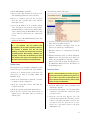
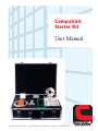
Computrols Starter Kit User Manual 8 2 6 L a f a y e t t e S t r e e t · N e w O r l e a n s , L o u i s i a n a · P h o n e : 5 0 4 . 5 2 9 . 1 4 1 3 · w w w. c o m p u t r o l s . c o m Welcome Welcome to the Computrols family of hardware and software. Computrols’ superior design department has been creating and developing hardware and software for over twenty-five years. We strive for simplicity, clarity, and ease of use in our product designs. Our software, Computrols Building Automation System (CBAS), is easy to install, maintain, and operate. Additionally, our hardware is manufactured in-house which allows us to maintain the highest level of quality control as well as the ability to quickly resolve any issues. Set Up The CBAS Starter Kit laptop and software are used to communicate with the 8 point controller included with the kit. The laptop is ready for use with your Starter Kit – all software and license files have been installed, and IP address configuration has been completed for you at our production facility. Please follow these simple instructions to connect the laptop to the 8x controller: 1. Unpack laptop, software package, and documentation. 2. Plug laptop in to power source and turn on. 3. Plug 24V power supply on 8x controller into outlet. Starter Kit Contents 4. Power on 8x controller. Software (enclosed in black plastic CD case) CBAS Starter Kit CD (1) Computrols Silver and Red USB Flash Drive (1) Contains: ◦ CBAS User Manual in .PDF format ◦ LICENSE3.TXT file ◦ INSTALL.EXE file Green Dongle Software Protection Device (1) The dongle is the “key” that allows the software license to function. CBAS How-To Video CD 5. Insert green USB software protection device into any available USB port on laptop. Hardware Computrols 8x DDC Controller (1) Computrols 8x Terminal Board (1) Dell Laptop (1) Computrols Hand-Held Terminal (1) 7’ Category 5e Crossover Patch Cable (1) 24V Power Supply (1) Belimo LM24-SR Damper Actuator (1) Damper Post Clip for Actuator (1) 24VDC Relay (1) 10K Type3 Thermistor (1) Keys for Brief Case (2) Documentation Datasheet for 8x DDC Controllers (1) 6. Connect crossover cable from controller Ethernet port to laptop Ethernet port. 7. Open CBAS. Operating CBAS Creating a New Database 1. From the Database menu, click New Database. 2. Enter a name for the database and hit Enter. 3. Select C:\CBAS for the directory and hit Enter or click OK. 4. A folder will be created to contain the database files. Hit Enter or click the Create Database NOW! button. After a short time, the new database will open in Editor Mode/Hardware View. You can now create Channels, Controllers and Points, in that order. Datasheet for Hand Held Terminal (1) Starter Kit User Manual (1) Adding a TCP/IP Controller 1. Click the TCP/IP For Controllers channel and click Controllers. 2. Click Add a BASNet Controller. The following window will appear: 3. Put in a name that describes its location or use and will distinguish it from other controllers. 4. Choose a controller type from the next drop down list. The controller that comes with the Starter Kit is an 8x. 5. Put in the IP Address of the controller and hit enter. Controllers come from the factory with a default IP address of 192.168.1.199. That number can be changed using the Hand Held device that comes with the Starter Kit (See instructions below). 6. Select to Create a New Blank Database then click Add Controller Now! Note: If you have multiple controllers of the same type (in a real database), that have identical point configurations, you can create a template by clicking on the controller in Hardware View, and click Save Database as Template. The Template will be stored in C:\CBAS\Templates. When Creating a Database from Template, you will browse to that directory and select your template. Point names can be changed to match the name of the new controller in the template wizard. Adding Points Each panel has a given number of hardware points based on the type of controller. The entire database can have up to 60,000 software points. Note: To add points, you must be in Editor Mode and Hardware View. 5. To add a Software Point, Click Add a Software Point on the bottom line of the list. 6. Type in a descriptive and unique name for the point. It can contain up to 32 Characters. 7. Hit Enter, and select a configuration from dropdown list. 8. Hit Enter and Enter again, or click the Add Point NOW! button. The point has been added. To change any programming or add logic, schedule, PID to a point, click the point, then Program. See the CBAS User Manual for more information on Programming Points. Removing Points 1. Click on the channel that contains the controller to which you want to add points. Note: It is recommended that you remove any logic on the point you are removing, before removing it. Also, any logic or PID, etc. that causes a Point Relation to the point in question should be removed. In order to remove a point, you must be in Editor Mode. 2. Click the Controllers button and find the controller in the list. 1. From the Main menu, click on Database and click Remove A Point. 3. Click the controller and click the Points button. 2. From the list that appears, select the channel that contains the controller that contains the point you want to delete. 4. From the list of points, click Add a Point on whichever line, 1 through 8, where you want to add the point. 3. From the next list that appears, select the controller that contains the point that you want to delete. You will be asked twice if you are sure you want to delete the point. If you are sure, answer “Yes.” You will no longer see the point in Hardware view. 2 Attaching Devices to the Controller 1. If you haven’t already, you should now attach the provided devices to the proper points on the terminal board. Attach the 24VAC leads from the transformer to the 24VAC terminals on the 8x terminal board and plug the primary side of the transformer to a 110VAC outlet. 2. Plug one end of the 7’ Category 5e Crossover Patch Cable into the RJ45 connector on the top of the 8X controller and the other end into the network interface card on the computer. 3. Turn the On/Off switch on the controller to On and the 10 Mbps Link light should light up yellow. Go to Real Mode and command the points: ◦ In CBAS, go to the system menu and click the IP address in the controller channel in CBAS by clicking on the IP address and then ‘program’. 7. Type in the matching IP address 192.168.1.199) and then re-start CBAS. (i.e., Remember, your computer’s local IP address is a static IP address different from the one assigned to your controller and your controller channel. Following the steps above, the local IP address on your computer is 192.168.1.192 and the controllers’ IP address is 192.168.1.199. Hand Held Instructions The Hand Held Terminal is very easy to use. Just plug it in to the hand-held terminal on the board and it will power up. The first screen gives you the firmware version. Close Database. ◦ Once the database is completely closed, click Database, Open Database, click Real Mode, select your database folder and click OK. If everything is configured correctly, within a few minutes, the database should download to the controller and the status will be Normal. Troubleshooting a Controller Connection If, after connecting via the crossover cable, the communication status on the controller channel indicates ‘lost’ complete the following steps: Commanding a Point 1. Press Enter, and Enter again to get to the Modes menu. 2. Press 1 and Enter to see a list of points on the board. 3. Arrow up or down to see all the points. Press Select to command any command-able point. 4. Press 1 to command and 2 to place the point in Auto. Changing a TCP/IP Setting 1. Press ESC to return to the Modes Menu. 1. In CBAS, click Hardware View 2. Click on the Controller Channel 3. Click on Controllers 4. The number within the address field should be the same as the address assigned to the controller (sent from the factory as 192.168.1.199 or if you connected via a router XXX.XXX.X.199 to match your network for the first three parts). 5. To determine the IP address of the controller, connect the hand held terminal to the controller, press ‘select’, ‘enter’ and then press ‘3’ (web) and enter. The controller’s IP address will appear. 2. Press 3 and Enter to view and change TCP/IP settings. 3. The first setting you will see is the TCP/IP address. Arrow up or down to see other TCP/IP settings. Press Select to change a setting, then type in the numbers and dots to separate them. When you enter a 3-digit number, the dot will be added for you. 4. After completing the number, press Enter and you will be prompted to reboot the board. 5. Turn the board off then back on for the settings to take effect. 6. If this number does not match the IP address of the controller on the controller channel, change 3 View CBAS How-To Videos! www.computrols.com/howto Questions? At Computrols, we value our dealers. Starter Kit technical support is available Monday through Friday, 9am–5pm Central Time by calling (504) 5291413. For 24-hour emergency technical support, please call (504) 529-1413 and a technical support representative will assist you promptly. For more help with programming databases, see the CBAS Help File by going to the System menu and selecting CBAS Help. The same information is included in the CBAS Manual, which is included in your package and can be copied from our website at www.computrols.com/manuals. 4