1
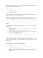
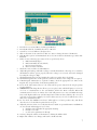
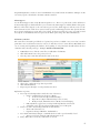
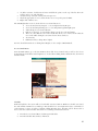
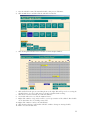
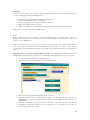
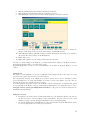
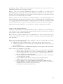
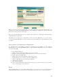
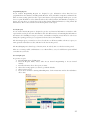
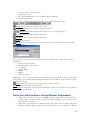
Computrols CBAS Access Control User Manual 826 Lafayette Street • New Orleans, Louisiana • Phone: 504.529.1413 • www.computrols.com Requirements .............................................................................................................. 2 Firmware .................................................................................................................... 2 Key Controller ............................................................................................................ 2 Software ...................................................................................................................... 2 License ........................................................................................................................ 2 Communications Architecture ............................................................................... 2 Adding Access Control to an Existing Database................................................ 2 Creating a New Access Control Database ........................................................... 3 Create a new database ............................................................................................... 3 Configure Workstation .............................................................................................. 4 Add Brain Controllers ................................................................................................ 5 Add Readers ............................................................................................................... 5 Program Readers ........................................................................................................ 6 Alarm Suppress............................................................................................................... 8 Add Points to Readers .................................................................................................... 8 Relay ............................................................................................................................... 9 Administration ............................................................................................................... 9 Program Passwords .................................................................................................... 9 Access Control Menu ............................................................................................... 10 Schedules................................................................................................................... 10 Companies ................................................................................................................ 12 Automatic Downloads ......................................................................................... 17 Add Interlocks .......................................................................................................... 18 Overtimes ................................................................................................................. 18 Car/Card Junction.................................................................................................... 20 Passwords ................................................................................................................. 20 Card Lockout ........................................................................................................... 21 Card Pictures ............................................................................................................ 22 Access Workstation ................................................................................................. 22 Setting up a GW (Graphic Workstation) ................................................................ 23 How to add the Access Control Pictures to the Workstation ............................ 24 Reports ......................................................................................................................... 24 Programming Reports .......................................................................................... 25 Activity Reports ................................................................................................... 25 Generating Reports .............................................................................................. 25 Quick Start Guide to Access Control Elevator Programming ...................... 26 AC-3 Wiring Diagrams ........................................................................................ 27 Requirements Firmware Upgrade firmware on host controller (8X, 16X, etc.) to v11.3. o Must be Access Control Firmware o While burning firmware with DDCC program, you have to key the controller. AC2 and AC3 controllers must have Opto-22 firmware. Key Controller You must key the controller to the jobsite using DDCC, in conjunction with the Dongle (hardware lock) for the jobsite. A password is required to make changes with the Handheld on all Access Control Brain controllers (8X, 16X, 32X, 64X). Software Use CBAS version 3.1.10 or later. License Access Control is an Add-On feature for CBAS. Without this add-on feature listed in the license text file, you will not be able to see Access Control menu items, even in Editor Mode. Communications Architecture The following figure shows a simple representation of the communication topology employed in the Computrols CBAS Access Control system. Adding Access Control to an Existing Database If adding Access Control to an existing database, you may have to upgrade the database to the minimum version for Access Control. Open in Editor mode first and Access Control tables will be added to the database automatically. When you open the database, sign on as Computrols and go to System, Program Passwords. Click Edit then click a User. On any User that you want to be able to View Access Activity, Edit Access Control, or Acknowledge Access Control Alarms, you have to check the appropriate boxes. 2 Only on existing databases, you have to go to Utility Mode, System Menu and Scale db on the DPU. There are some new things listed at the bottom: 1. 2. 3. 4. 5. 6. Attributes, n/a, only for CBAS Enterprise Areas, default is 510 Cards, default is 20,000 Card-Area, default is 30,000 Reader-Area, default is 30,000 Company, default is 1,000 In the above list, default means how the database is scaled by default when a new database is created. Change the categories to a sufficient number for the building. When finished changing the numbers in the “Num Records” column, click Save Changes and Close. Determining how many Cards or Areas you have is easy. To determine how many Card-Areas you need to scale the Host Controller database for, multiply the number of Areas in the Brain (Host) controller, by the number cards that may have access to those Areas. For example: Let’s say that you have an 8X hosting 10 Readers and each Reader is designated as a separate Area. You also have 2000 Cards that have access to all of those Areas. 10 Areas X 2000 Cards = 20,000 Card-Areas. If there are some Cards that do not have access to some Areas, it is more difficult to get an exact count. You have to take the number of Cards for each Area and add them together. To cover all of your bases, just use the above formula. There is a limit of 38,000 Card-Areas per Brain Controller. If you need more Card-Areas, add more Brain Controllers. 1. 2. 3. 4. 5. 6. 7. Go back to editor mode In Hardware View, add the controller(s) that will host Access Control to the TCP/IP for Controllers Channel. Program your 8X, 16X, 32X or 64X as an Access Control 8, 16, etc. When you click Add Controller Now, it will take a little longer to add than a normal controller, because more tables and channels are added. Once the host controller is added, click it and click the Channels button. Click Host or Secondary Opto channel, then Controllers. This is where you program the AC3s. Then add the points to the AC controllers. When you make changes to an Access database, you have to manually download to controllers. This is because they go offline to download. If you have a lot of controllers, it could take a while. You don’t want doors becoming inaccessible during high traffic periods. After making changes that require a download, CBAS will display “Access Control Download Required” in the Header Points space, below the Main Menu. Creating a New Access Control Database Create a new database 1. If you have a database open already, click Close Database from the System Menu. 2. From the Database menu, click New Database. 3. Enter a name for the database and hit Enter. 4. Select C:\CBAS for the directory and hit Enter or click OK. 5. Hit Enter or click the Create Database NOW! Button. A folder will be created to contain the database files. 3 After a short time, the new database will open in Editor Mode/Hardware View. The only existing channels in the new database are the TCP/IP for Workstations Channel, and the TCP/IP for Controllers Channel. You can now create Controllers and Points. Configure Workstation Before you start setting up your database, there is an easy way to setup default values, such as Job Number, Reader Defaults, and Activity View display settings. Reader default times will be 0 if you do not change them. Doors will not open if the Door Strike value is set to 0. 1. From the Main Menu, go to System, then Configure Workstation. 2. 3. In Activity View Setup, check the boxes for the types of activity you want to see. Click the Access Control Defaults button. 4. Enter the Card Job Number in the appropriate field. Each time you add a Card, the number will be added for you. 4 5. In the Reader Defaults section, choose the appropriate values for each section and field. If you do not put in values, they will default to 0, and all Readers will have to be edited later. See the later section, “Program Readers” for brief explanations of Reader Defaults. 6. In the last section, check the first box to sort the Card List by Card Number, instead of Last Name. 7. Check the next box to show the Company under the Picture of the cardholder in Activity View. 8. If “Display DENIED Access attempts as Alarms” is checked, CBAS will display an Alarm Banner at the top of the screen when Access is denied to any card. These Alarms must be acknowledged by someone who has rights to do so. 9. If you are using the Panasonic IRIS Scanner, check the final box. 10. There is a feature in the Card Edit screen that allows you to lockout a card immediately. Put in a number in the field for the default number of minutes that a Card will be denied. The feature is explained in the Cards section. 11. Other check boxes in this section are self-explanatory. Voltages must match the specifications of the Wiegand card reader and door strike device. 12. ESC to save changes. By displaying an Alarm for denied access, Administrators will always know when someone is trying to gain access with a lost, stolen, expired Card, or is trying to gain access to an un-allowed Area. Add Brain Controllers In order to create a RS 485 channel to host AC controllers, you must first add a controller to the TCP/IP for Controllers channel. This controller, called the Brain or Host, contains a copy of the database for all Readers it hosts. The channels that host the AC controllers will be added automatically. 1. 2. Click the TCP/IP for Controllers Channel then Controllers. Click Add a Controller. 3. 4. 5. 6. 7. 8. Give the controller a descriptive name. Choose Access Control 8, 16, 32, or 64 for the configuration. Give the controller an IP address that will work on the subnet. Choose to Create a New Blank Database. Click Add Controller Now! After a short wait, the controller will be added to the list. Add Readers A Reader is a controller that interfaces to the actual reader/keypad device. Supported Readers consist of the Computrols AC3. Now you can add AC3s (one for each door) to the controller that is hosting the communication channel. 1. Click the controller you added in the last section. 5 2. 3. 4. 5. 6. 7. 8. 9. Click Channels. Notice that the RS485 Host and Secondary channels are already programmed as OPTO-22 on Controller channel type. Click the Host Channel, then Controllers. The list is in order by address. Click Add a Controller on address 1. (Actually, it could be any address you want to use) As in the above figure, give the controller a descriptive name. In the “Configured as” drop–down list, choose AC3. Click Add Controller Now and the controller will appear on the list. Add a controller for each door by repeating steps 5 through 8. Program Readers Once you have added Readers, there may be some settings that have to be changed, especially if you did not set the Access Control Defaults, as covered in Configure Workstation previously. Below is the Program screen for a Reader. If a Reader belongs to an Area that is an anti-passback area, then it MUST be either an IN or an OUT reader. An IN reader will allow a card into an Area, whereas an OUT reader will allow a card out of an Area. A Card that has been used on an IN reader MUST be used on an OUT reader in the same Area before it may be used on an IN reader again. A Reader may consist of a Reader, a Keypad or both, connected to an AC3. Generally, the Reader and Keypad will be part of the same piece of hardware. If both a Reader and Keypad are required for entry, then the ‘Has Reader’, ‘Has Keypad’ AND ‘Both Reader AND Keypad Required for Entry’ must all be selected. If a Reader and Keypad are both present, BUT either may grant access, then the ‘Both’ option should not be selected. 6 1. 2. 3. 4. 5. 6. 7. 8. 9. 10. 11. 12. 13. 14. 15. 16. 17. From the Access Control Menu, click Program Readers. From the Readers list, click Edit, then choose a Reader. You will see a screen similar to the figure above. Click on the name of the controller, in this case, AC3, to change the name of the Reader. If the Reader is part of an Anti-Passback Area, select In or Out for the Reader type under AntiPassback. If there is a Door Contact (gives status of door; open/closed), choose a. NO for Normally Open b. NC for Normally Closed (default) c. Res for Supervised input d. None for no Door Contact Check the next box if there is an Exit Button. Adjust Wiegand Voltage and Strike Voltage to match the hardware. The range is 5 to 24 Volts. The hardware will not operate properly unless the voltage is set correctly, and can be damaged by setting the voltage too high. Check Has Reader box if needed. 26 Bit is the reader type and is chosen by default. Check Has Keypad if there is a Keypad also, and choose whether a 4 or 6 digit code is required. If Both Keypad and Reader are required for Entry, check the appropriate box. Then, if the Keypad entry is required first, check the Keypad First box. If you check “Show Denied Access”, the reader will beep twice instead of the long beep when access is granted. IMPORTANT: Checking this box allows you to stop the feature which will grant access in case of a loss of communication to the card database held in the Brain controller. When this communication is lost for one minute, the reader will grant access to any card within the range between the highest and lowest card. It is important to make sure that cards have the correct job code and you do not have multiple job codes for this reason. A job code of 0 will allow access to many more cards than normal. Do not check “Use MultiDoor Lockout”. This applies to a future product only, and allows other doors to be locked when a particular door is open. Adjust the amount of time, in seconds, that the Door Strike is open and the Buzzer and LED are on, as well as the Alarm Suppress (see below): a. Click the time field under the appropriate heading b. Default is 5 seconds c. See below for explanation of Alrm Sp You may change the address of the Reader by clicking the Address field. Right-click or ESC to save changes and return to the Reader List. 7 Programming Readers can also be done from Hardware View and from the Area Editor. Changes on this screen may require a download to the Host or Brain controller. Alarm Suppress Set the Alarm Suppress time in the Reader Program screen. There is a point in the reader called Door Contact with Suppress, which will allow you to monitor the alarm suppress. Add an Alarm to that point. When a valid card is swiped or the exit button is pressed, the alarm suppress will stay active for the desired amount of time. If the door contact is still open after Alarm Suppress time has expired, then the Door Contact with Suppress point will go into alarm. If the Door Contact becomes open and no Card was swiped, or the Exit Button was not pressed, the Alarm point will go into Alarm immediately. Add Points to Readers The controllers come with a predefined set of points, but you have to add the ones you need. If you add a point that is not needed and not wired to a device, it will show a “Lost” status when in Real Mode. For ease of viewing and organizing the database, the beginning of each point name should include the door or Reader name, then the point type. Example: REAR DOOR BUZZER. 1. 2. 3. In Hardware View, click the controller you added then click Points. Click Add a Point next to the point you need. Give the point a name that includes the name of the door. 4. 5. 6. Choose the configuration type that is provided. Click Add Point Now! Repeat steps 2 through 5 on each point that is needed. Explanation of points: 1. Door: Supervised Output that controls the state of the Door. o Can be commanded to Lock, Open or Ready Lock: Door will not Open with Card Swipe Open: Door is Open and Card Swipe is not necessary Ready: Default. Means that Door is Ready for Card Swiping o In Ready Mode, toggles between SwipeA and SwipeB when card is used o A Schedule can be placed on the Point Program Screen of this point 2. Last Access Value: Counter Input that shows last Card use. o Shows a D if denied access o If granted, shows Job Number, Card Number. 3. Door Strike: Momentary Output, commands the door strike open if normally closed o Time period can be changed on Reader Program screen 4. Relay: This is the second relay on the AC3. See below. 8 5. Alarm Suppress: Momentary Output, used for suppressing an alarm system while door is open. Explained in previous section. 6. Buzzer: Momentary Output, sounds the buzzer to tell user that the door is unlocked. o Coincides with Door Strike 7. Green LED: Momentary Output, Light on reader turns green to tell user that the door is open 8. Door Contact: Can be Binary or Supervised Input, open contacts tell you door is open. Supervised Input requires 1.9K Ohm resistor. See wiring diagram. 9. Exit Button: Binary Input, input used to tell the door to open and let user out. 10. Door Contact with Suppress: Enables Alarm on Open Door Contacts when Card has not been swiped. See previous section for details. 11. Adjust the Wiegand Voltage to match the manufacturer’s specifications for the Reader. ( Be careful: the wrong voltage can break hardware) 12. Adjust the Strike Voltage to match the manufacturer’s specifications for the Door Strike hardware. Relay This point controls Relay 2 on the AC3 controller. Relay 2 can be used for anything and can be controlled by a Swipe, Logic or Schedule. For example, it could be used to control a secondary car gate, which could be Open during scheduled hours. Then, during closed hours, will also Open when a card is Swiped. Administration Once you have added all of your door controllers and their points, you can begin adding Areas, Companies, Schedules and Access Cards. You might want to expand and restrict Rights for other users of the CBAS Server. Program Passwords If someone else will be the Administrator, or at least have the responsibility of adding Cards, you will need to add a User Account and Password for them. This way, you will have a record of who added each card. Additionally, you may want to add User Accounts for security personnel that will monitor Activity View. There is also a Passwords item on Access Control menu. This feature will allow you to restrict CBAS users to edit Cards in certain Areas only (this is covered in a later section). When a new Database is started, the Default User Account has rights to do everything in CBAS. You should first add a User Account for yourself and remove most rights, other than viewing Activity, from the Default User. When a User is logged on, that user will be logged off automatically after a default period of 30 minutes of inactivity, and the Default User is logged on. The inactivity period can be changed by going to Configure Workstation on the System Menu. To edit or add users: 1. From the Main Menu, go to System, Program Passwords. 2. Click Edit then click a User. 3. On any User that you want to be able to View Access Activity, Edit Access Control, or Acknowledge Access Control Alarms, you have to check the appropriate boxes. Edit Access Control allows the User to add Cards and other Access Control Menu functions. 4. Once you have checked and un-checked the appropriate boxes, right-click or ESC to save the changes. 9 5. 6. 7. 8. To add a new User, click the Insert button and slide the pointer to the top of the list where the red line can be seen, and click there. To add a Group, insert the red line in the Groups area. Check the appropriate boxes to allow the User access to specific parts of CBAS. Right-click or ESC to save. The main Rights that need to be checked for Access Control Users are: Access Control Activity Reports – to view and print Activity Report Access Control Program Reports – to view and print Programming Reports Acknowledge Access Control Alarms Edit Access Control – view and make changes on the Access Control Menu There are other Edit Access Control items that allow you to narrow down what the user can do while editing Access Control items: Areas, Cards, etc View Activity Edit Passwords (to change Users’ rights) For more detailed instructions on editing Users’ Rights, see the complete CBAS Manual. Access Control Menu From the Main Menu, go to the System Menu, then click Access Control and you will see the Access Control Menu. If Schedules and Companies are needed when adding Cards, add them first, then Areas and then Cards. Schedules Each Card added to the system will need a Schedule associated with it. Without a schedule associated, the card will have 24-Hour access. Add up to 128 schedules here. You might want to have a Schedule for each Company, or Area, in order to facilitate adding Overtime later. Overtime will be discussed in a later section. Let’s add a Schedule that allows access during normal business hours. 1. 2. From the Access Control Menu, click Program Schedules. From the Schedule List window, click Insert. 10 3. 4. Give the Schedule a name, like Normal Schedule, then press or click Enter. Click the Edit button, and then click the Schedule from the list. 5. Click the Program Schedule button, and then click Use Graphical Editor. 6. Click and hold in the gray area and drag down to the right. This will open a box covering the scheduled times. (See above) The entire week can be scheduled with one drag. 7. Click the Access button and the area will turn dark blue. 8. To schedule 24 hour access, click the 24 Hour button. 9. Right-click or ESC to escape and you will see a text representation of the schedule. The schedule can be edited there also, by clicking on any field. 10. Right-click or ESC to return to the Schedule List 11. Click the Insert button to add another Schedule, or Edit to change an existing schedule. 12. ESC to close the Schedule List. 11 Companies In order to group cards, it can be useful to assign Companies to Cards. Grouping in this way also gives you more sorting options when printing Reports. 1. 2. 3. 4. 5. From the Access Control Menu, click Program Companies. From the Company List window, click Insert. Give the Company a name, location and phone number. Right-click or ESC to return to the list. Add more Companies, or click the Edit button, and then click the Schedule from the list. Note: Do not use punctuation in the Company name. Areas Before cards can be used, Areas must be associated with them. Areas are really groups of doors or Readers, each of which are controlled by AC3 controllers. Adding controllers was covered in the previous section, Add Readers. An Area is an easy way to give people access to many readers at the same time. CBAS is limited to 500 Areas. Areas may not overlap. In other words, Readers may not belong to more than one Area. There is one exception: elevator Readers may belong to more than one Area. Elevators will be covered in a later section. Anti-passback Areas cannot span multiple Brain controllers. Non-Anti-passback Areas can span over multiple Brain controllers, however, this is not recommended and should only be done as a last resort. 1. 2. From the Access Control Menu, click Program Areas. From the Area List window, click Insert to see the Area Editor. 3. 4. Click the field under Area Name and give the Area a name. If the Area is intended to be an Anti-Passback Area, select Anti-Passback Area. If Area is an Anti-Passback Area, at least 2 readers must be added. 1 must be an IN Reader and 1 must be an OUT Reader. Click the field under ‘Area is in Controller’ and choose the controller that is hosting the Reader/Door controllers. It will be an Access Control 8, 16, etc, and only one is allowed per Area. (Unless absolutely necessary) 5. 12 6. 7. 8. Click the Add Reader button and choose Readers from the list. Click the Remove Reader button and choose Readers to remove. Click Edit Readers and you will be taken to the Program Screen for that controller. 9. From there you can change the way the door behaves. Click on the buttons to change the amount of time the door stays open, the buzzer buzzes, and the LED stays lit. 10. Adjust Wiegand Voltage and Strike Voltage to match the hardware. The range is 5 to 24 Volts. (Be careful: The wrong voltage can break hardware) 11. Right-click to close. 12. Right-click or ESC to save the changes and return to the Area List. Any time you make changes to the database, you must download the changes to the Brain controllers. Download Controllers will be covered in a later section. Programming Readers can also be done from Hardware View and from Program Readers (covered earlier). Anti-Passback The purpose of anti-passback is to prevent a cardholder from passing back his or her card to a second person in order to gain entry into an access-controlled area. The anti-passback features of the CBAS Access Control System can be used to maximize security, prevent fraudulent use of cards and maintain an accurate record of the number of people who are currently in any one area (possibly for safety reasons). In an Anti-passback Area, there must be an ‘In Reader’ and an ‘Out Reader’. A Card that has gained access to through an ‘In Reader’, must go out through an ‘Out Reader’ before being allowed to re-enter. Anti-passback Areas cannot span multiple Brain Controllers. See the previous section for instructions on Anti-Passback programming. Adding Access Cards 1. From the Access Control menu, click Program Cards to see the Card List. The list is in order by the first four letters of the Last Name of the Card Holder. (The list can be sorted by card number, by going to System, Configure Workstation, Access Control Defaults) 2. To edit an existing Card, click Edit and select the Card from the list. If the Edit button cannot be selected, right-click to de-select the previous button. 13 3. 4. 5. To delete an existing Card, click Delete and select the Card from the list. If the Delete button cannot be selected, right-click to de-select the previous button. (Delete button added in version 3.1.2) To Search for a Card, click Search and enter the first four letters of the First or Last Name from the Card Search screen. You can search by as little as the first letter. Right-click to close the Search screen and the card list will contain all Cards meeting the search criteria. You can also search by Company and Card number. To add a new Card, click Insert and the Card Editor screen will appear. 6. 7. Click each field to enter the appropriate information. To choose a Company, highlight the Company in the Company List, and then right-click or ESC to exit the list. 8. If a Company has not yet been added, click on the Edit Companies button to add the Company. 9. Enter the Job Code and Card Number from the card. 10. If there is a Key Pad associated with a Reader in the Area, then add the Key Code number. 11. Select a Card Status: a. Free: means that the card has been returned and is ready to be assigned to another user. The card is disabled until it is reassigned. b. Lost: means the card has been lost. The card is disabled when in this status. c. Used: means that the card is in use and the user will gain access when the card is swiped, as long as the schedule for that card allows it. d. Expired: this status is achieved automatically when card expires, access is not granted. e. Expire On Use: will expire X number of days after Card used for the first time. See Note below. 12. If you want the card to expire, click the field next to Card Expiration Date and use the calendar to choose a date. a. Use the arrows at the top of the calendar to move a month forward or backward. b. Click a date and it will be placed into the field. c. Click the Clear Expiration button to disable Expiration. 14 13. Check Notify on Use to receive a notification at the CBAS Server or GW when the card is swiped. 14. Check Allow Access if Locked. This feature will allow an administrator or security officer entrance even if the door has been locked. See note below for details. 15. Car Transmitter. Check this box if the Card will have a Car Transmitter associated with it. This feature is explained in a later section. 16. To have a picture displayed when access is granted, place a jpg or bmp picture of the user in C:\CBAS\AccessControlPictures. 17. Click the Photograph Name field to access the Picture Viewer. 18. In the Picture Viewer, click the Browse button and select the picture in the Access Control Pictures folder. 19. The following fields are for information purposes only: a. Location b. Phone Number c. Car Tags d. Comments 20. The date when the card was last edited is shown just above the Areas list. 21. The date and time that the card was created is shown along with the user who was logged on at that time. 22. Click the Edit Area List button and choose Areas that the user will have access to. 23. To simply duplicate the Areas that have been given to another User, click the Copy From button and choose a user from the list. 24. While in the Area List, right-click or ESC to save selections and return to the Card Editor. 25. Once again, right-click or ESC to save the card and return to the Card List. 26. You must manually download to the controller any time you add a card or make changes to the status of a Card. Note: Expire on Use is a feature that allows cards to be programmed that will expire X number of days after they are used for the first time. This feature is used mainly for visitors who will only need access for a predetermined number of days. The user must turn the Card in before leaving on the final day. When you check the “Expire on Use” checkbox, the “Expiration Date” item changes to “Card Expires After.” Click the field and enter the number of days before expiration. A zero (0) here means that it will expire at the end of the day in which the card was used. A one (1) means it will expire and the end of the day after the card was first used. When the card is first used the controller will send a message to the CBAS Server. When the Server receives the message, it will change the card from "Expire On Use" to "Used", then set the Expiration Date to the specified date. After that, the card is treated like a regular USED card with expiration. But, just like any other Access Control change, it must be downloaded to the controller before it will take affect. So, the CBAS installation MUST be using the Automatic Access Control Download feature. This feature is explained in a later section. Note: The "Allow Access if Locked" for an Access Control Card ONLY applies to the Door. In other words, if the Door point on a particular Reader is locked. The Door must be locked by Schedule, Logic1, or Logic2, for ‘Allow Access If Locked’ to work. Also, the Card must have access to the door it is trying to get into and the Card Schedule must allow it. If the door is locked by Operator, Logic3, or Logic4, access will still be denied. Note: In order to give someone else the Rights to add and edit Cards, you must add them as a User. For instructions, see the first sub-section under the Administration section, Program Passwords. 15 Add Areas and Schedules to Cards Once you have added Cards, you must give them the Areas where they are allowed to access, as well as Schedules and Interlocks, if necessary. In addition to adding Areas in the Card Editor, they can be added in the Card Area Editor, where you have a choice of adding Areas to Cards, or Cards to Areas. 1. 2. From the Access Control Menu, choose Program Card/Areas. You will see the Access Control Card Area Editor. See below. 3. 4. 5. 6. 7. 8. 9. 10. 11. 12. Select a Card from the list on the left side, and you will see a list of Card Areas on the right. To add Areas to Cards, click the Edit Area List button. From the Area List, select Areas then right-click to save and close the list. If you do not add a Schedule for an Area, 24-hour access will be granted to the Area. To add a Schedule, click the field in the Schedule List column. Choose a Schedule from the list then right-click to save and close. To add an Interlock, click the field in the Command List column and choose one from the list. Right-click twice to save and close the list. To change a Schedule or Interlock, click on the appropriate field. To Remove Areas from a card, click the Edit Area List button and the Area List will appear. 16 13. The Areas highlighted in green have already been added to the list on the right. Click the green Areas on the main list to remove them from the list on the right. 14. Right-click twice to save and return to the Card Area Editor. 15. Once you have added Areas and Schedules, right-click or ESC to close the Card Area Editor. Note: The database on the Access Control (Brain) controller may need to be scaled to handle the number of Card/Areas. If each Card has access to all Areas, then the number of records is figured using the formula: # of Cards X # of Areas. Download Controllers Whenever changes are made to the database, such as adding a card or changing a schedule, the changes must be manually downloaded to the Host/Brain controllers. Do not do this during high-traffic periods, as the Reader will reboot and be disabled for a few seconds. Editing anything in the Reader Program screen causes a download to the Brain controller of that Reader automatically. So there is no need to use the Access Control Download option when editing the Reader parameters. Only things like Cards/Areas need to be manually downloaded, or automatically downloaded (see next section). 1. 2. From the Access Control Menu, click Download Controllers. You will see a progress screen while the controllers are downloaded to. 3. On the next screen, Access Control brains are shown along with some statistics about how many records are used in their databases. The download is complete. Right-click or ESC to return to the Access Control Menu. 4. Automatic Downloads For your convenience, there is a way to set up CBAS so that downloads occur overnight at a time when few people, if any, will be using the access control system. If you rely on this feature, new cards and changes to existing cards will not take effect until the next day. To set up Auto-Downloads: 1. Go to the System Menu, then Database Maintenance. 2. Click the Access Control Download button. 3. See below. When the download time is set to 00:00, there will be no download. Change the time by clicking on it and entering a time when there is very little traffic. 4. Right-click or ESC to save. 17 Add Interlocks Interlocks are Output points that will be triggered when a card is swiped. In order to add Interlocks, you must first add Automation points to the database. An Interlock will command any Binary or Momentary, Hardware or Software Output. You can set the Interlock to command the point On or Off. Enabling buttons in an elevator is one of the most common Interlocks. 1. 2. From the Access Control menu, click Program Interlocks. From the Interlock List, click Insert, and you will see the Interlock Editor. 3. 4. Click the Select Output Point field and choose a point from the list. Only Binary and Momentary Output points are listed, including the second Relay Output point on the AC3, if it has been programmed. Click the next field and choose On/Off, Start/Stop, etc. For the Command Priority, Logic 1 will override a Schedule that is already in effect on the point. Choose Logic 2 to override a Logic 1, etc. Right-click to save the Interlock. Go to the Card/Area Editor to add the Interlock to a Card. 5. 6. 7. 8. 9. You can now command a software point from an interlock. The Software point must be in the same controller as the Hardware Binary Input that the interlock is programmed on. You cannot toggle the state of a software point from within an Interlock. You can only command it to a value. You can command analog and multistate points as well as binary points. You can still toggle the state of a hardware binary output from within an interlock. When commanding a software point from within an interlock, the speed will be much slower. The change of state should happen within 1 second. When an interlock commands a hardware output the change of state is within a few hundred milliseconds. Note: You must have Firmware rev 11.4 or later for this feature to work. For more information on Command Priority, go to Text View, then Priority Summary. There is a list showing what command type has priority over others. Don’t forget to Download Controllers after making changes. You must be in Real Mode to do this. Overtimes What if a Company, tenant, or a particular area needs to have access past the normal schedule? You can easily add an Overtime Schedule to the normal Schedule. 1. From the Access Control menu, click Program Schedules. 18 2. 3. 4. Click the Edit button, then the Schedule you want to add overtime to. Click Program Overtime Schedule. Click Use Graphical Editor. 5. Highlight the part of the Schedule that you want to Add Overtime to by clicking and dragging down and to the right, then releasing. Click Overtime ACCESS and the time period will change color. To change to a future week and schedule Overtime, click the Next Week button. Dates are shown in the column on the left. Right-click or ESC to save and you will see a text representation of the Overtime. You can edit here by clicking on any field. Right-click or ESC to save and return to the Schedule list. 6. 7. 8. 9. Don’t forget to Download Controllers after making changes. You must be in Real Mode to do this. You should occasionally purge old Overtimes by going to System, Database Maintenance. Otherwise, you will eventually get to a point where you cannot add new Overtimes. Reader Areas Readers only exist in 1 area, with the exception of elevator Readers. The Reader Area Editor is where you add Areas to Elevator Readers. DO NOT use the Reader Area Editor unless you are adding Areas to Elevator Readers! 1. 2. From the Access Control menu, click Program Reader/Areas. Select a Reader from the list on the left side of the editor and on the right you will see the Areas the Reader exists in. 19 3. 4. 5. 6. To add Areas to an elevator Reader, click Edit Reader Area List. Select Areas from the list and right-click to exit. Click any line in the Command List column to add an Interlock to an Area. Right-click or ESC to save changes and return to the Access Control menu. Don’t forget to Download Controllers after making changes. You must be in Real Mode to do this. Car/Card Junction If a location is using a CR-NMR microwave reader, there is a device called the Combi-Booster, which is an active tag that is specifically designed to be used in combination with HID prox cards. The CombiBooster enables simultaneous identification of the HID proximity card and the embedded vehicle ID, resulting in rapid combined driver and vehicle monitoring. On the windshield, the Nedap 2N-9888888 Combi-Booster - HID Proximity Card Integrated Dual ID Tag is mounted and the HID card is placed inside. The Car/Card Junction menu item brings up an editor which allows you to track relationships between Cards and Car Transmitters (Combi-Booster). If a Cardholder has a Car Transmitter, check the Car Transmitter checkbox in the Card Editor. Then, go to System/Access Control/Car Card Junction/Program. This is where you relate Access Cards to Car Cards. For more information on this subject, please contact Technical Support. Passwords The Passwords feature on the Access Control menu allows you to restrict the Areas that CBAS users can add, remove, and edit Cards to/from. When you open the Passwords feature, you will see the same list of Users found in Program Passwords on the System menu. For the User to be able to Program Cards and add Areas to them, you must first give them that right in Program Passwords. 1. 2. 3. 4. On the Main Menu, go to System, then click Program Passwords. To add a new User, click Insert and then click somewhere in the list. To Edit an existing User’s rights, click Edit, then click the User from the list. Check all of the boxes next to items on the list containing the words Access Control. There are 2 items referring to Reports, and the rest pertain to Editing Access Control. If you check Edit Access Control Cards, but do not check Edit Access Control Areas, then the User will not be 20 able to add Areas to a Card. More detailed instructions in previous Administration/Program Passwords section. 5. Once you have checked the appropriate boxes, right-click or ESC to close. 6. You may edit another User, or close the Password List screen. 7. Now go to System, Access Control, then Passwords, if you want to restrict the Areas in which a User can or cannot edit Cards. 8. Click a User from the list. 9. By default, Users are allowed to Edit Cards in all Areas. To remove Areas, click the green button at the bottom of the screen. 10. Click an Area on the main list and it will be removed from the secondary list on the right. 11. Once you have finished editing a User, right-click or ESC to close. 12. You may edit another User, or close the Password List screen. Card Lockout Card Lockout is a feature that allows the CBAS Access Control Administrator to immediately lockout a Cardholder for 1 day (1440 Minutes). This forces the Cardholder to talk to the Administrator/Security upon arrival. In the Edit Card screen there is a Lockout Card button. Click it and it adds that user to a list of users that will be denied access. The User will be blocked from all access for the next 24 hours, or until they are removed from the lockout list. With the Lockout Card feature, an Access Control download is NOT required. The system is limited to a maximum of 14 users that can be locked out at any one time, and it takes about 20 seconds for the lockout to take affect. Go to Card Lockout on the Access Control menu to check Lockout status or to add/remove Cards to/from the list. The Card Lockout Editor can also be accessed from the Lockout Card button in the Edit Card screen. Clicking this button adds the Card to the list immediately. 1. 2. 3. 4. 5. 6. Go to System, Access Control, then Card Lockout. Locked out Cards will be listed along with the number of minutes remaining before the lockout ends. To add a Card to the list, click Edit Card Lockout List on the top left of the screen. Select a Card from the list, then right-click. The Card will begin counting down from 1440 minutes. To remove a card from the list, click the top right button, then click the Card. Right-click or ESC to exit the Card Lockout Editor. Activity View To monitor current Card use activity, use Activity View. The last 200 Card swipes will be listed, including the users’ name, Access granted or denied, door, and time of use. If a card is denied access, the line will be red and it will show the reason for denial. Possibilities for denial are: Unknown Card, Disabled Card, and Lock by Schedule. If you get the message “Denied DB Error”, this means that you need to scale the database on the controllers and the server to accommodate the number of Card/Areas. If pictures are associated with Cards, each time a Card is used, the picture is displayed on the upper right side of the Activity List. 1. 2. 3. 4. 5. From the Main Menu, click Text View, then Activity. You will see a list of Cards that have been recently used. To the upper right of the list, you will see a picture of the last Card user to gain entrance. Click on a line in the list and the picture of the user will be shown in the bottom right. Right-click or ESC to exit Activity View. 21 Activity View Setup Go to the System Menu, then Configure Workstation. In the Activity View Setup section, check the appropriate boxes. To display Automation Alarms (generally HVAC and Lighting points), check the first box. The second check box is to display Fire Alarms, if a Csimon Fire Panel is present in the system. To NOT show Access Control Activity in Activity View, uncheck the third box. To specify which Readers to display activity from, check the next box, then click the Select Readers button and choose Readers from the list. To NOT show pictures, uncheck the next box. If the Show Pictures box is checked, check the Show on Bottom box to make pictures display at the bottom of the screen instead of the side. Card Pictures As stated earlier in the Adding Cards section, you can associate a picture with the Cards in the database. Each time a card is used, the picture will be displayed in Activity View. 1. Pictures must be jpeg or bitmap format and should be placed in the C:\CBAS\AccessControlPictures folder. 2. If the afore-mentioned folder does not exist, add it using Windows Explorer. 3. Go to Program Cards on the Access Control menu. 4. From the Card list, click Edit, then the card you want to add a picture to. 5. Click the Browse button and select the picture from the AccessControlPictures folder. 6. Click the Open button. 7. Right-click or ESC to save and close the Card Editor. 8. It is NOT necessary to Download Controllers after adding pictures. Access Workstation Many administration and monitoring functions can also be performed on a CBAS Graphic Workstation. Graphic Workstation Mode (GW) allows a workstation computer with CBAS installed on it to connect to and share the server’s database. A GW is used to monitor a database, but not to make major 22 programming changes. Adding and removing Channels, Controllers and Points, as well as some administrative functions, are not possible on a GW. However, some Access Control administration functions are available on the GW, such as Adding/Editing Cards and Schedules. Activity View and Reports work the same as they do on the Server. In order to view pictures in Activity View on the GW, you must copy the Access Control Pictures folder from the Server to the GW and place it in C:\CBAS. ONLY 1 computer at a time can edit the Access Control Card database. So if editing is taking place on a GW, the DPU and all other Workstations will not be able to edit until the GW that is editing finishes. An error message will be displayed informing the user that editing is not possible at the present time. A GW is finished editing when the user either does a download, logs off, or there is no activity for 20 minutes. Adding and connecting a GW will be covered in this section, as well as copying the pictures folder. Setting up a GW (Graphic Workstation) In order to set up a GW, the Server and the GW must be able to communicate on a network basis. In other words, if you can see the GW in the Network Neighborhood window of the DPU, it is possible. It is also possible to connect a GW over the Internet. When connecting as a GW, the CBAS version on the GW must be the same (or nearly the same) as the Server, or the Server will refuse the connection. Version 1.6.X will not work with 2.0.X, which will not work with 2.1.X, etc. Before you can set up a GW, you will need the IP address of the Server and the GW, as well as the computer name of both. To get this info: In Windows 98, from the windows desktop, click on Start, Run, type winipcfg, and enter. In Windows 2000/XP, click on Start, Run, type command and hit Enter. At the prompt, type ipconfig and hit Enter. Write down the host name of the DPU and the IP address of both computers. Close the window. First, you must set up the DPU to accept the GW: 1. In Editor Mode, click on Database from the main menu, and then click on Add A GW. 2. The first window will ask you for a name for the GW. The default is “NEW GW”. Enter a name that describes the location or function of the GW computer. Click next. 3. Enter the IP address of the GW. Click finish. 4. If you go to Hardware View, TCP/IP Channel, Controllers, you will see the GW you created, with a status of LOST. 5. Close the database and reopen in real mode. Now go to the GW computer. 6. In CBAS, click on System on the main menu, then Close Database. 7. Once the database is closed, click on Database, Open Database, and Remote GW. 8. Enter the IP address of the DPU, and the name of the GW exactly as you entered it on the DPU. Click Connect and the database should open. 9. The GW Connection screen is shown below: 23 When you connect using the method above, the entire database is zipped and downloaded to the workstation. It resides in C:\CBAS\[GW Name]. If the database has changed since the last connection was made, the changes will be downloaded. Notice the” Use File Sharing Connection” checkbox in the figure above. Advantages and disadvantages of File Sharing are outlined also. File Sharing is not required or recommended for an Access Control GW. However, you may want to activate file sharing in Windows in order to transfer Access Control Pictures to the GW whenever cards are added. How to add the Access Control Pictures to the Workstation For full instructions on file-sharing permissions and sharing files in Windows see the Advanced Programming section of the CBAS Manual. Once you have shared the CBAS folder on the Server and can access it from the GW: 1. 2. 3. 4. 5. 6. 7. 8. 9. 10. Open Windows Explorer. Double-click on the My Network Places icon on tree (left side). Navigate to the Server computer and double-click on it to see the shared folder list. Double-click on the CBAS folder. Right-click the AccessControlPictures folder and click copy. From the Explorer tree on the left, open the C:\CBAS folder Ctrl-V or right-click in an open space then click Paste. Answer Yes to overwrite. Close Windows Explorer. The new pictures should now show up in the lower picture position of Activity View if you click on one of the activity records on the left. Reports From the Main Menu, go to the Reports Menu. There are 2 categories of Access Control Reports: Programming and Activity. All reports can be generated then printed or saved to a variety of formats. 24 Programming Reports Access Control Programming Reports are designed to give information about what has been programmed into the database, including Cards, Readers, Areas, Schedules, Companies, and Interlocks. There are many sorting options for these reports. For instance, when generating the Card report, you can choose to print All Cards or Selected Cards, and sort the results by Name, Card Number, Company, or Status. You can choose to generate the report in short format (limited information) or long format (all Information). There is also a check box for showing Areas on the report. Activity Reports Access Control Activity Reports are designed to give the user historical information on Card use. The reports in this section give the same information, but offer different ways of formatting that information. For instance, the Card Report can give you name, card number, Company, status. Then, for each access during the reporting period, it gives you granted or denied, door, time and date. The Area Report gives you Card access for a selected Area or All Areas. Under each Area, it gives you name, granted or denied, Door, date, and time for the chosen time period. The Everything Report is a hard copy of Activity View, in order by time over the chosen time period. There are too many possible combinations to cover them all here, so try a few different reports and find some that suit your needs. Generating Reports To generate a report: 1. From the Main menu, click Reports. 2. From the Reports Menu, choose either Access Control Programming or Access Control Activity. 3. From the submenu, choose the report you want. 4. Choose the sorting options you want or go with the defaults. 5. Choose a time period. 6. If you choose to Enter a Starting and Ending Date, click on Start Date and use the Calendar to choose date. 25 7. 8. 9. 10. Use the arrows to change the month. Click a date to select. Select Start and End Times or leave at default, which is midnight. Click Generate Report Once a report is generated, CBAS displays it on the screen with the following tool bar: First Page: Takes you to the first page in the report. Previous Page: Takes you to the previous page in the report. Page Indicator: This example indicates that you are on 3 of 360 total pages. Next Page: Takes you to the next page in the report. Last Page: Takes you to the last page in the report. Print: Prints the report. Export: Allows you to export the report a specified location. The following screen appears when you select this icon. You can export reports in any of the following formats by clicking the arrow beside the Format dropdown menu: Character-separated values Comma-separated values (CSV) Excel (XLS) Acrobat (PDF) HTML ODBC Many other types Additionally, you can select the Destination by clicking the arrow beside the Destination drop-down menu. When you are satisfied with the Format and Destination, click OK. If you do not wish to export, click the Cancel button. Zoom: Changes the view of the report on screen by zooming in and out. Total: The number of listings a report includes. % Indicator: Percentage that report has completed. Remember that you can cancel report generating at any time to get a partial report. Quick Start Guide to Access Control Elevator Programming 1. 2. Add an Access Control controller to the TCP/IP controller channel. The controller must have enough points to control the number of elevators times the number of floors (buttons). Ex. 4 Elevs X 8 Floors = 32 points Add points to the controller for each Elev/floor; Elev 1 FL 1, Elev 1 FL 2, etc. Make these points Momentary Outputs. On the program screen for these points, set your “On Time”, which is 26 3. 4. 5. 6. 7. 8. 9. how long the relay stays on to keep the button active. Click Switch Contacts if necessary, to make the relays reverse acting. Add a reader for each Elevator. Edit the Reader and check the appropriate boxes on the Reader Program screen. Add points to the Reader. Because there is no strike etc, Elevator Readers generally only require 2 points: Door and Last Access. Add Areas for each floor, but do not add Readers at this time. Add Interlocks for each Elev/Floor. Select the output points created in step 2. Select Start or Stop based on whether the point is NO or NC. If other logic may command a point, adjust logic level accordingly. Go to the Reader/Area Editor and select a Reader, then add Areas to each Elevator Reader. In the “Command List” column, add an interlock point for each area. Add Schedules so that users don’t have to swipe a Card during normal business hours. Add a Binary Output Event Sequence Software point to the controller hosting the button relay momentary points. Add a Schedule to that point. Add Logic level 2 to that point: When the schedule point is on, start the button points, else Auto the same points. Make the logic evaluate more often than the duration of the momentary outputs. In other words: if the momentary outputs are set to be ON for 10 seconds, make the logic evaluate every 5 to 8 seconds. This should keep the momentary points ON the whole time that the Schedule is ON. There are limits to how many lines can be written into a logic statement (125). Another way of doing the logic would be to put it on each individual output point, referencing the Schedule point in the statement. AC-3 Wiring Diagrams Wiring diagram with strike powered from the AC-3. Can be “Normally Open” or “Normally Closed.” 27 Wiring diagram with strike powered separately from the AC-3. Can be “Normally Open” or “Normally Closed.” 28