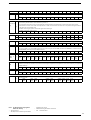
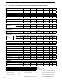
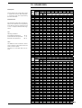
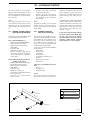
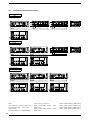
1
English
NSB
R134a
FREECOOLING
TECHNICAL MANUAL - INSTALLATION - MAINTENANCE
Air/water chiller with screw compressors
G 272 KW ÷ 1414 KW
FC 280 KW ÷ 1469 KW
INSBFCPY 0810 6310902_01 replacing 6310902_00 del 0710
SELECTION INSTRUCTIONS
Dear Customer,
Thank you for having purchased an AERMEC product. This product is the result of many years of experience and indepth engineering research, and it is built using top quality materials and advanced technologies.
Moreover, the CE mark guarantees that the appliances respond to the requisites of the European Machinery Directive
on the subject safety. The qualitative level is under constant surveillance and AERMEC products are therefore a synonym of Safety, Quality and Reliability.
Product data may be subject to modifications deemed necessary for improving the product without the obligation to give prior notice.
Thank you again
AERMEC SpA
AERMEC S.p.A. reserves the right at any moment to make any modifications considered necessary to improve our products and is not
obliged to add these modifications to machines that have already been fabricated, delivered or are under construction.
2
Index
1.
1.1.
1.2.
Warnings regarding the documentation .................................5
Use in compliance with destination .................................................5
Preservation of the documentation ................................................5
2.
Fundamental safety regulations .................................................5
3.
Product identification ......................................................................5
4.
4.1.
4.2.
4.3.
Description of the unit ....................................................................6
Models available .......................................................................................6
Available versions ....................................................................................6
Set-ups available.......................................................................................6
5.
5.1.
5.2.
5.3.
5.4.
5.5.
5.6.
Description of the components ...................................................7
Cooling circuit............................................................................................8
Frame and fans ........................................................................................8
Hydraulic components...........................................................................8
Control and safety components ........................................................8
Electric components ..............................................................................8
Electronic adjustment............................................................................9
6.
Accessories ...................................................................................... 10
7.
7.1.
Technical data .................................................................................. 12
NSB 1251A ÷ 2202A "HIGH EFFICIENCY
and in FREECOOLING mode.............................................................. 12
NSB 2352A ÷ 4502A "HIGH EFFICIENCY
and in FREECOOLING mode.............................................................. 13
NSB 4802A ÷ 7203A "HIGH EFFICIENCY
and in FREECOOLING mode.............................................................. 14
NSB 1251E ÷ 2202E" LOW NOISE HIGH EFFICIENCY
EXECUTION and in FREECOOLING mode .................................... 15
NSB 2352E ÷ 4502E" LOW NOISE HIGH EFFICIENCY
EXECUTION and in FREECOOLING mode .................................... 16
NSB 2352E ÷ 4502E" LOW NOISE HIGH EFFICIENCY
EXECUTION and in FREECOOLING mode .................................... 17
7.2.
7.3.
7.4.
7.5.
7.6.
8.
8.1.
8.2.
Selection criteria ............................................................................ 18
Operation limits ..................................................................................... 18
Design data Dir 97/23/CE ............................................................ 18
9.
9.1.
9.2.
9.5.
9.6.
Coefficient Factors ........................................................................ 19
Cooling Capacity and Input Power ................................................. 19
“High Efficiency Versions” ....................................................................9
“High Efficiency Versions In Silenced Execution” .....................20
Corrective Coefficients Versions with Freecooling Only ......20
10.
10.1.
Glycol ethylene mix ........................................................................21
How To Read The Glycol Curves ..................................................... 21
11.
11.1.
11.2.
Pressure drops ...............................................................................22
Pressure Drops And Minimum Water Content .....................22
Minimum Water Content..................................................................23
12.
12.1.
Pumps .................................................................................................24
Pumps Selection ................................................................................... 24
13.
Sound Data .......................................................................................25
14.
Calibration of safety and control parameters....................27
15.
15.1.
15.2.
Dimensions .......................................................................................29
High efficiency versions dimensions (A) and high efficiency
in silenced execution (L) .....................................................................29
Pumps weight.........................................................................................29
16.
16.1.
Weights and barycentres ...........................................................30
Base dimensions...................................................................................30
17.
17.1.
17.2.
Handling .............................................................................................32
Lifting instructions ...............................................................................32
Lifting points ...........................................................................................32
18.
18.1.
Warnings regarding safety and Standards.........................34
Safety warnings .....................................................................................34
19.
19.1.
19.2.
Installation ........................................................................................35
Choice of place of installation ..........................................................35
Positioning ...............................................................................................35
20.
Anti-vibration mounts position..................................................36
21.
21.1.
21.2.
Hydraulic circuit .............................................................................39
Internal hydraulic circuit (supplied as per standard) ............39
External hydraulic circuit (not provided) .....................................39
22.
22.1.
22.2.
22.3.
22.4.
Hydraulic connections position................................................. 41
Single-module connections position.............................................. 41
Two-module connections position ..................................................42
Three-module connections position..............................................44
Versions with pump connections...................................................45
23.
23.1.
23.2.
23.3.
23.4.
Electric connections......................................................................45
Electric lines and data ........................................................................45
Remote controls connection ...........................................................45
Connection to the mains electricity power supply .................45
Electrical data ........................................................................................46
24.
24.1.
24.2.
24.3.
Commissioning ................................................................................ 47
Preparation for commissioning ..................................................... 47
Commissioning ...................................................................................... 47
System discharge ................................................................................ 47
25.
25.1.
25.2.
Maintenance ....................................................................................48
Warnings regarding maintenance ...............................................48
Extraordinary maintenance .............................................................48
26.
26.1.
26.2.
Disposal..............................................................................................49
Disconnecting the unit........................................................................49
Dismantling and Disposal..................................................................49
27.
27.1.
Improper use....................................................................................49
Important safety information ..........................................................49
To install the appliance, please comply with the warnings regarding safety, contained in these instructions
Moving parts hazard
Danger, disconnect voltage
High temperature hazard
Generic danger
Voltage hazard
i
Useful information and warnings
3
AERMEC SpA
I-37040 Bevilacqua (VR) Italia – Via Roma, 44
Tel (+39) 0442 633111
Telefax 0442 93730 – (+39) 0442 93566
wwwaermeccom - info@aermeccom
NSB
SERIAL NUMBER
EC DECLARATION OF CONFORMITY
We, the undersigned, hereby declare under our own responsibility that the assembly in
question, defined as follows:
NAME
NSB
TYPE
FREECOOLING CHILLER
MODEL
To which this declaration refers, complies with the following harmonised standards:
CEI EN 60335-2-40
Safety standard regarding electrical heat pumps, air conditioners and dehumidifiers
CEI EN 61000-6-1
CEI EN 61000-6-3
Immunity and electromagnetic emissions for residential environments
CEI EN 61000-6-2
CEI EN 61000-6-4
Immunity and electromagnetic emissions for industrial environments
EN378
Refrigerating system and heat pumps - Safety and environmental requirements
UNI EN 12735
UNI EN 14276
Seamless, round copper pipes for air conditioning and cooling
Pressurised equipment for cooling systems and heat pumps
Therefore complying with the essential requirements of the following directives:
- LVD Directive: 2006/95/CE
- Electromagnetic Compatibility Directive 2004/108/CE
- Machinery Directive 98/37/CE
- PED Directive regarding pressurised devices 97/23/CE
The product, in agreement with Directive 97/23/CE, satisfies the Total quality Guarantee procedure (form H) with certificate
n.06/270-QT3664 Rev.3 issued by the notified body n.1131 CEC via Pisacane 46 Legnano (MI) - Italy
Bevilacqua
14/12/2007
Marketing Manager
Signature
4
1.
1.1.
USE IN COMPLIANCE WITH
DESTINATION
The AERMEC NSB chillers are built in
compliance with Technical Standards and
the acknowledged technical safety regulations. These appliances are designed and
built for cooling and must be used accordingly in compatibility with their technical
features. However, dangers to the user
or third parties may arise, as well as damage to the appliance and other objects,
in the event of improper use and use not
in compliance with that declared.
Any use not expressly indicated in this
manual is not permitted and consequently AERMEC will not assume any respon-
WARNINGS REGARDING THE DOCUMENTATION
sibility for damage occurring owing to
failure to comply with these instructions.
1.2.
PRESERVATION OF THE
DOCUMENTATION
The installation instructions along with all
the related documentation must be given
to the user of the system, who assumes
the responsibility to keep the instructions
so that they are always at hand in case
of need.
READ THIS DOCUMENT CAREFULLY,
the appliance must be installed by qualified and prepared staff, in compliance
with national legislation in force in the
2.
We must remind you that the use of products that employ electrical energy and
water requires that a number of essential safety rules be followed, including:
This appliance is not suitable for use
by persons (including children) with limited physical, sensory, or mental capacities or those lacking experience
or knowledge, unless they are supervised or instructed regarding the use
of the appliance by a person who is
responsible for their safety. Children
must be supervised to make sure
that they do not play with the appliance
and flammable substances near to
the chiller
It is prohibited to touch the appliance
when you are barefoot and with parts
of the body that are wet or damp
It is prohibited to open the doors to
access the internal parts of the appliance, without first having first positioned the system master switch at
off
It is prohibited to disperse, abandon
or leave the packing materials within
the reach of children, as they are a
potential source of danger.
PRODUCT IDENTIFICATION
The NSB can be identified by:
TECHNICAL
PLATE
- Packing label
that shows the product identification
data
- Technical plate
Positioned on the longitudinal member of the electric box.
The validity of the warranty shall be void if
the above-mentioned indications are not
respected.
FUNDAMENTAL SAFETY RULES
It is prohibited to carry out any technical or maintenance operation before
the unit has been disconnected from
the electrical mains by positioning the
system master switch and the control panel main switch at "off"
It is prohibited to modify the safety or
adjustment devices without the manufacturer’s authorisation and precise instructions
It is prohibited to pull, detach or twist
the electrical cables coming from the
unit, even if it is disconnected from
the mains power supply
It is prohibited to leave containers
3.
country of destination (Ministerial Decree 329/2004).
The appliance must be installed in a way
to make maintenance and/or repairs
possible. The appliance warranty does
not cover the costs for ladders, scaffolding, or other elevation systems that may
become necessary for carrying out servicing under warranty.
PACKING
LABEL
NOTE
Tampering, removal, missing identification plate or other does not allow the
safe identification of the product and
will make any installation or maintenance operation to be performed difficult.
5
4.
DESCRIPTION OF THE UNIT
4.1.
AVAILABLE MODELS
− “COOLING ONLY” maximum external
temperature allowed 46°C, (42°C
for size 1601-3002-3202-34025003-5203) Acoustic protection
cover for compressor for silent functioning.
Air-cooled liquid chillers with axial fans for
outdoor installation (IP24 protection rating). They have one or more cooling circuits. The evaporators are the dry expansion shell and tube type. The entire range
has up to three twin-screw compressors.
The new NSB A range is characterised
by high efficiency values (EER) also thanks
to the use of R134a refrigerant, which
allows to obtain much higher efficiency
than equivalent products functioning with
R407C.
This result is also fruit of an accurate study and dimensioning of all internal components in order to make the most of the
features of the R134a refrigerant gas.
PARTICULAR attention has been paid to
the dimensioning of the heat exchangers,
compressors and fans.
All units are inspected and delivered complete with refrigerant and oil load, (only
hydraulic and electrical connections must
be made on site).
4.2.
of every prolonged pause period) it is extremely important that the compressor
sump oil has been previously heated, by
means of the power supply of the relevant electric resistance, for a period of at
least 8 hours. The sump resistance is powered automatically when the unit stops
as long as the unit is live
AVAILABLE VERSIONS
4.3.
− "HIGH EFFICIENCY" Maximum external temperature allowed 46°C, (42°C
for size 1601-3002-3202-34025003-5203) acoustic protection
cover for compressor for more silent
functioning
− “SILENCED (E)” Extra to the high efficiency version (A) this configuration
envisions a silencer on the pressing
line and an electronic phase cutting
device, which allows a reduction of
fan revs. on the variation of the environmental temperature conditions.
SET-UPS AVAILABLE
NSB range chillers are available in 32
sizes. By appropriately combining the variety of options available, it is possible to
configure every model in the NSB range
in a manner that satisfies all specific implant requirements.
The following configurer shows how to
make up the sales code in the 16 fields
that make it up, representative of the options available.
ATTENTION
Before every unit start-up (or at the end
4.3.1. Configurer
1,2,3
4,5,6,7
8
9
10
11
12
13
14
15-16
NSB
1251
X
°
°
A
°
°
°
FB
Field
1, 2 ,3
Identification
NSB
4, 5, 6, 7
Sizes
8
Refrigerant
°
Standard
Y
Low temperatures (to -6°C)
X
With electronic valve
9
Cooling Only
10
Heat recovery units
°
Without recovery units
11
Version
A
E
High efficiency
High efficiency in silenced execution
Coils
°
R
S
V
In aluminium
In copper
In tinned copper
In painted aluminium
12
6
Model
°
1251-1401-1601-1801-2101-2401-140216 0 2 - 18 0 2 - 2 0 0 2 - 2 2 0 2 - 2 3 5 2 - 2 5 0 2 2 6 5 2 - 2 8 0 2 - 3 0 0 2 - 3 2 0 2 - 34 0 2 - 3 6 0 2 3902-4202-4502-4802-5003-52035403-5703-6003-6303-6603-6903-7203
13
Heat exchangers
°
PED Regulation
14
Power supply
°
3~ 400V - 50 Hz with fuses
2
3~ 230V - 50 Hz with fuses
4
3~ 230V - 50 Hz with magnet circuit breakers
5
3~ 500V - 50Hz with fuses
8
3~ 400V - 50 Hz with magnet circuit breakers
9
3~ 500V - 50Hz with magnet circuit breakers
15-16
Pumps
F0
FA
FB
FC
FD
FE
FF
FG
FH
FJ
FK
Without pumping unit
Pumping unit (pump A)
Pumping unit (pump A and reserve pump)
Pumping unit (pump C)
Pumping unit (pump C and reserve pump)
Pumping unit (pump E)
Pumping unit (pump E and reserve pump)
Pumping unit (pump G)
Pumping unit (pump G and reserve pump)
Pumping unit (pump J)
Pumping unit (pump J and reserve pump)
5.
DESCRIPTION OF THE COMPONENTS
Example NSB 2401 FB
KEY
1
2
3
4
5
6
7
8
9
10
11
12
13
14
15
16
17
duty pump
Collector
Stand-by pump
One-way valve
Gate valve
Expansion vessels (25 l x 2)
Intercepted charging assembly
Shell and tube heat exchanger
Liquid tap
Twin-screw compressor
Compressors compartment covered in
sound-absorbing material
Air exchange coil
Fans unit
Electric box
Intake safety valve (1st for circuit)
Dry fit (1st for circuit)
Thermostatic valve (1st for circuit)
7
5.1.
COOLING CIRCUIT
Compressors
High efficiency semi-hermetic screw
compressors with cooling capacity
adjustment by means of continuous
modulation from 40 to 100% (from 25
to 100% with electronic valve) and supplied with:
− Motor circuit breaker protection
− Oil discharge temperature control
− Electric resistance for heating oil
sump with compressor at a standstill
− Reset button.
Water side heat exchanger
Shell and tube direct expansion heat exchanger, suitably dimensioned to obtain
high performance.
Steel case with closed cell expanded
elastomer anti-condensation covering.
the shell and tube is made from copper
pipes with a special section that allows
high heat exchange associated to efficient draining. On request the heat exchanger can be equipped with an antifreeze electric resistance (accessory
to be mounted in the factory), which
protects the heat exchanger from external temperatures to -20°C, with the
aim of preventing the formation of ice
in stand-by mode. With the unit running, protection is assured by the outlet
water temperature probe
Solenoid valve
The valve closes when the compressor
switches off, blocking the flow of refrigerant gas to the evaporator
5.2.
FRAME AND FANS
Ventilation Unit
Helical type, balanced statically and dynamically. The electric fans are protected electrically by magnet circuit breakers and mechanically by anti-intrusion
metal grids, according to the IEC EN
60335-2-40 Standard
Support structure
Made in hot galvanised sheet steel with
suitable thickness and painted with polyester powders able to resist atmospheric agents through time
Acoustic protection cover
All NSB versions are per standard
made up from a thick sheet steel compartment and internally covered with
sound-absorbing material. It allows to
reduce the sound power level emitted
by the unit and also protects the compressors from atmospheric agents.
5.3.
HYDRAULIC COMPONENTS
Dry fit
With removable cartridge, it can withhold the impurities and eventual traces of humidity in the cooling circuit
Circulation pump/s
Whilst working with pump components
it offers a static pressure that is useful
for beating system pressure drops.
In the presence of a second pump (reserve), switch-over takes place manually by acting in the selector switch positioned inside the electric control board
Liquid indicator
Used to check the refrigerant gas load
and the eventual presence of humidity
in the cooling circuit
Filling unit
(only in versions with pump)
It is supplied with a manometer for display of the system pressure
Thermostatic valve
Mechanical valve, with external equaliser positioned at evaporator output,
modulates the flow of gas to the evaporator, depending on the heat load, in
a way to ensure correct heating of the
intake gas
Expansion vessels
(only in versions with pump)
Two 25 litre membrane vessels with
nitrogen pre-load.
5.4.
IP54 differential pressure switch (installed in series)
It has the task of controlling that there
is correct water circulation. If this is not
the case, it blocks the unit
Low pressure transducer
It allows to view the compressor intake
pressure value on the microprocessor
board display (one per circuit). Positioned on the low pressure side of the
cooling circuit, it stops compressor
functioning in the case of anomalous
work pressures
High pressure transducer
It allows to view the compressor flow
pressure value on the microprocessor
board display (one per circuit). Positioned on the high pressure side of the
cooling circuit, it stops compressor
functioning in the case of anomalous
work pressures
Double high pressure switch (manual
+ tool)
Factory calibrated, placed on the high
pressure side of the cooling circuit, it
stops compressor functioning in the
case of abnormal work pressures
Cooling circuit safety valve (HP, LP)
Calibrated at 22 bar HP - 16.5 LP. they
intervene by discharging the over/
pressure in the case of anomalous
pressures.
5.5.
Liquid and pressing line taps
They allow to shut-off the refrigerant in
the case of extraordinary maintenance
Silencer
Positioned on the compressor flow in
the E version. It contributes to attenuating noise emission
8
Three-way valve
Present on the water side of the freecooling circuit, it is an electric servocontrolled ON-OFF diverter valve.
Freecooling air-water exchanger
Passed over by water in the freecooling
functioning mode.
Made with copper pipes and aluminium
louvered fins blocked by mechanical expansion of the pipes.
It is the high efficiency type.
SAFETY AND CONTROL
COMPONENTS
ELECTRIC COMPONENTS
Electric control board
It contains the power section and the
management of controls and safety
devices. It is in compliance with IEC
60204-1 Standards and the Directives
regarding Electromagnetic Compatibility EMC 89/336/EEC and 92/31/
EEC. Moreover, all cables are numbered for immediate recognition of all
electric components
NOTE
Moreover, all cables are numbered for
immediate recognition of all electric
components
Door-lock isolating switch
IT is possible to access the electric control board by removing the voltage on
the opening lever of the control board
itself. This lever can be blocked with one
or more padlocks during maintenance
interventions in order to prevent undesired machine energising
Control keyboard
It allows the complete control of the
appliance. For a more detailed description, refer to the user manual
− Fuses and magnet circuit breakers for protection of the compressors, to be specified on ordering.
− Magnet circuit breakers for fan
protection
− Auxiliary magnet circuit breaker
protection
5.6.
ELECTRONIC ADJUSTMENT
The electronic adjustment of NSB chillers is made up from a control board
for each compressor connected to
each other in a network and a control
panel with display. In the case of multicompressor models the board that
controls compressor n°1 is the “MASTER” board while the others are “SLAVE”. Transducers, loads and alarms relative to the compressor that controls
are connected on each board, while the
general machine ones are only connected onto the master board
Microprocessor
- remote ON/OFF with external
contact without voltage
- Multi-language menu
- Phases sequence control
- Independent control of the individual
compressors
- Amperometric transformer
- Cumulative faults block signal
- Historical alarms function
- Daily/weekly programming
- Inlet/outlet water temperature
display
- Alarms display
- Integral proportional adjustment on
the outlet water temperature
- Programmable timer function
- Function with double calibration
point linked to an external contact
- Fan adjustment
- Can be interfaced with Modbus
protocol (accessory)
- Pump/s control
- Compressors rotation management
- Analogue input from 4 to 20 mA
- External air temperature probe
- "Always Working" function. In the
case of critical conditions (e.g. an
environmental temperature that is
too high) the machine does not stop
but can adjust itself and supply the
maximum power in those conditions
- Self-adapting “Switching Hysteresis”
work differential to always ensure
the correct functioning times of the
compressors even in plants with
low water content or insufficient
capacities. This system decreases
wear of the compressors
- AFFP “Anti Freezing Fan Protection”
system that periodically switches
the fans on when external
temperatures are very low
- PDC “Pull Down Control” system
to prevent the activation of power
steps when the temperature of
the water quickly approaches the
set-point. It optimises machine
functioning when working normally
and in t he pr esence of load
variations, thus ensuring the best
efficiency in all conditions.
For further information please refer to
user manual.
9
6.
1251
AER485P2
AK
only
AVX
2101
2401
1402
1602
1802
2002 2202 2352 2502 2652 2802
3002
•
•
•
•
•
•
•
•
•
•
•
•
•
•
•
E
E
E
E
E
E
E
E
E
E
E
E
E
E
E
512
512
501
501
505
511
511
511
511
511
511
509
•
•
•
•
•
•
•
•
•
•
•
Spring anti-vibration mounts
501
PRV
501
501
506
Allows to control the chiller at a distance
•
ROMEO
•
•
•
•
The ROMEO device allows the remote control of the chiller from a mobile phone with WAP browser. It also allows to send alarm
or pre-alarm SMS up to threes GSM mobile phones, even if they do not have WAP browser. The AER485 is included in the kit.
The AER485P2 accessory must be added to this kit
•
•
•
•
•
•
•
•
•
•
•
•
•
•
•
•
RIF
Connected in parallel to the motor, it allows a reduction of the input current
400V - 3 500Hz
(1)
MULTICHILLER
KRS
GP
301
301
301
301
371
411
161X2
161X2
201X2
201241
241X2
241301
301X2
301X2
301X2
301X2
Control system for control, switch-on and switch-off of the individual chillers in a plant in where multiple units are installed in
parallel. It is possible to choose from several command logics: sequential, homogeneous, combi. The accessory is supplied in
an IP65 rated box
•
•
•
•
•
•
•
•
•
•
•
•
•
•
•
•
(1)
Heat exchangers electric resistance for outdoor temperatures to -20°C
4
5
5
5
5
5
5
5
5
5
5
5
5
5
5
5x2
It protects the external coil from accidental blows and prevents access to the area below where the compressors and cooling
(1) circuit are housed
300M
6.6.1.
10
1801
AK: Acoustic kit
This accessory allows further noise reduction by means of:
- An optimised compressor cover using high density material without lead that allows to reduce vibrations even further
- Anti-vibration mounts in AV rubber for compressors in order to reduce their vibrations so as to prevent damage caused to
(1)
the pipes and use of flexible joints
- Isolation of the larger pipes to reduce the typical noise of the gas
- Isolation in the most critical points
E
−
−
1601
This accessory allows connection of the unit to BMS supervising systems with RS485 electric standard and MODBUS protocol
•
E versions
1401
ACCESSORIES
300M
300M
400M
(1) Accessories only applicable in the factory
AK Acoustic kit
RIF Re-phasers available only with 400V-
500M
−
−
500M
300B
300B
400B
500B
3-50Hz power supply
KRS heat exchangers electric resistance
GP Protection Grid
500B
500B
500B
500B
500B
300Mx2
3202
AER485P2
E versions
only
3602
3902
4202 4502 4802 5003 5203
5403
5703
6003
6303
6603
6903
7203
This accessory allows connection of the unit to BMS supervising systems with RS485 electric standard and MODBUS protocol
•
AK
3402
•
•
•
•
•
•
•
•
•
•
•
•
•
•
•
AK: Acoustic kit
This accessory allows further noise reduction by means of:
- An optimised compressor cover using high density material without lead that allows to reduce vibrations even further
- Anti-vibration mounts in AV rubber for compressors in order to reduce their vibrations so as to prevent damage caused to
(1)
the pipes and use of flexible joints
- Isolation of the larger pipes to reduce the typical noise of the gas
- Isolation in the most critical points
E
AVX
E
E
E
E
E
E
E
E
E
E
E
E
E
E
E
518
521
521
517
515
524
525
525
527
527
530
530
•
•
•
•
•
•
•
•
•
•
•
Spring anti-vibration mounts
507
PRV
513
516
518
Allows to control the chiller at a distance
•
•
•
•
•
ROMEO
The ROMEO device allows the remote control of the chiller from a mobile phone with WAP browser. It also allows to send alarm
or pre-alarm SMS up to threes GSM mobile phones, even if they do not have WAP browser. The AER485 is included in the kit.
The AER485P2 accessory must be added to this kit
•
•
•
•
•
•
•
•
•
•
•
•
•
•
•
•
RIF
Connected in parallel to the motor, it allows a reduction of the input current
400V - 3 500Hz
(1)
MULTICHILLER
KRS
301X2
(1)
(1)
301
371
301
411
371
411
411X2
301X3
301X3
301X3
301X2
371
301X2
411
301
371
411
301
411X2
301
411X2
411X3
Heat exchangers electric resistance for outdoor temperatures to -20°C
5X2
5X2
5X2
5X2
5X2
5X2
5X2
5X3
5X3
5X3
5X3
5X3
5X3
5X3
5X3
5X3
It protects the external coil from accidental blows and prevents access to the area below where the compressors and cooling
circuit are housed
300Mx2
300M
400M
400Mx2
400M
500M
(1) Accessories only applicable in the factory
− AK Acoustic kit
−
301X2
Control system for control, switch-on and switch-off of the individual chillers in a plant in where multiple units are installed in
parallel. It is possible to choose from several command logics: sequential, homogeneous, combi. The accessory is supplied in
an IP65 rated box
•
•
•
•
•
•
•
•
•
•
•
•
•
•
•
•
GP
6.6.2.
301X2
400M
300Mx2 300M
400Mx2 400Mx2 400M 400M
500Mx2 500Mx2
400Mx3
500Mx3 500Mx3
500M
400M 400Mx2
500M 500M 500Mx2 500Mx2
−
−
3-50Hz power supply
KRS heat exchangers electric resistance
GP Protection Grid
RIF Re-phasers available only with 400V-
11
7.
7.1.
TECHNICAL DATA
NSB 1251A ÷ 2202A "HIGH EFFICIENCY AND IN FREECOOLING MODE
COOLING
Cooling capacity
Total input power
Evaporator water flow rate
Evaporator pressure drop
kW
kW
l/h
kPa
FREECOOLING
Cooling capacity
Total input power
Total pressure drop
1251A 1401A 1601A 1801A 2101A 2401A 1402A 1602A 1802A 2002A 2202A
272
304
338
408
465
518
285
324
377
429
480
91
104
115
144
157
177
103
119
133
153
168
46830 52360 58070 70250 79960 89100 49040 55670 64810 73720 82630
48
30
36
43
32
37
27
32
43
48
34
280
12
121
291
12
125
301
12
108
403
16
153
486
20
135
503
20
176
285
12
118
297
12
102
393
16
142
452
20
143
491
20
152
2.98
23.33
4.22
2.92
24.27
4.24
2.94
25.10
4.30
2.84
25.21
4.24
2.97
24.29
4.20
2.92
25.17
4.28
2.77
23.73
4.20
2.73
24.76
4.22
2.82
24.56
4.20
2.81
22.59
4.23
2.86
24.56
4.24
160
24
248
338
180
24
310
460
196
24
355
489
238
32
363
497
267
40
418
626
400V-3-50Hz
299
179
40
24
468
279
690
226
205
24
304
266
225
32
353
308
261
40
401
352
288
40
442
366
1
1/1
1
1/1
1
1/1
1
1/1
1
1/1
twin-screw
1
2
1/1
2/1
2
2/1
2
2/1
2
2/1
2
2/1
56-100
49-100
43-100
42-100
56-100
49-100
43-100
42-100
56-100
49-100
43-100
42-100
56-100
49-100
43-100
42-100
56-100
49-100
43-100
42-100
28-100
24-100
22-100
21-100
28-100
24-100
22-100
21-100
28-100
24-100
22-100
21-100
28-100
24-100
22-100
21-100
28-100
24-100
22-100
21-100
1
V / 4"
1
V / 5"
1
V / 5"
1
V / 5"
Shell and tube
1
1
1
V / 6" V / 6" V / 5"
1
V / 5"
1
V / 5"
1
V / 6"
1
V / 6"
kW
kW
kPa
EFFICIENCY INDEX
A
FC
A
EER
ESEER
ELECTRICAL DATA
Power supply
W/W
W/W
V
A
FC
FLA
LRA
Nominal current
Maximum current
Peak current
COMPRESSORS
Type
Number
Number per circuit
A
A
A
A
n°
n°/n°
PARTIAL LOAD
VT Std
Partial load
VT ele
Pf.
%
Pa.
%
Pf.
%
Pa.
%
EVAPORATOR
Type
Number
Hydraulic connections
FANS
Type
Number
Air flow rate
Input power
Current absorbed
SOUND DATA
Sound power
Sound Pressure
DIMENSIONS
Height
Width
Length
empty WEIGHT
PUMPS
Input power
Current absorbed
Weight
n°
Tipo/ø
Axial
n°
6
6
6
8
10
10
6
6
8
10
10
A/FC m3/h 102000 102000 102000 136000 170000 170000 102000 102000 136000 170000 170000
A/FC kW
12
12
12
16
20
20
12
12
16
20
20
A/FC
24
24
24
32
40
40
24
24
32
40
40
94.0
62.0
95.0
63.0
97.0
65.0
97.0
65.0
98.0
66.0
98.0
66.0
96.0
64.0
97.0
65.0
97.0
65.0
98.0
66.0
98.0
66.0
2450
2200
3780
3760
2450
2200
3780
3770
2450
2200
3780
3840
2450
2200
4770
5000
2450
2200
5750
5950
2450
2200
5750
5980
2450
2200
3780
4010
2450
2200
3780
4030
2450
2200
4770
4730
2450
2200
5750
5740
2450
2200
5750
5790
FA
4
55
109
FC
55
75
117
FE
75
10
121
FG
92
125
140
FJ
11
15
148
A
A/FC dB(A)
A/FC dB(A)
mm
mm
mm
kg
kW
A
kg
DATA DECLARED ACCORDING TO EN14511:2004
cooling
- Input water temperature
12 °C
- Produced water temperature
7 °C
- External air temperature
35 °C
- ∆t
5k
12
56-100
49-100
43-100
42-100
Frecooling
- Input water temperature
- External air temperature
- Glycol
NOTE
Pf. Cooling capacity
Pa. Input power
15 °C
2 °C
0%
- SOUND PRESSURE measured in free field
conditions at a distance of 10 mt. with directi-
vity factor Q=2 in compliance with ISO 3744
- SOUND POWER Aermec determines the
sound power value on the basis of measurements made in compliance with ISO 9614-2
Standards, with respect to the requisites
implemented by EUROVENT certification
7.2.
NSB 2352A ÷ 4502A "HIGH EFFICIENCY AND IN FREECOOLING MODE
COOLING
Cooling capacity
Total input power
Evaporator water flow rate
Evaporator pressure drop
kW
kW
l/h
kPa
FREECOOLING
Cooling capacity
Total input power
Total pressure drop
2352A 2502A 2652A 2802A 3002A 3202A 3402A 3602A 3902A 4202A 4502A
501
522
553
584
642
675
746
817
873
926
983
177
186
200
215
219
230
259
288
300
321
334
86240 89860 95190 100520 110420 116130 128320 140500 150210 159350 169060
37
40
32
35
33
36
42
43
38
42
35
498
20
168
505
20
184
514
20
197
522
20
226
592
24
116
602
24
108
705
28
130
807
32
153
889
36
144
907
36
165
989
40
156
2.83
24.91
3.71
2.81
25.24
4.25
2.76
25.69
4.25
2.72
26.10
4.21
2.93
24.68
4.28
2.94
25.10
4.3
2.88
25.16
4.26
2.84
25.21
4.19
2.91
24.70
4.18
2.89
25.19
4.24
2.95
24.73
4.17
305
40
464
413
322
40
487
429
344
40
518
456
366
40
548
458
376
48
588
464
400V-3-50Hz
391
434
48
56
620
673
464
594
476
64
726
618
505
72
781
745
537
72
831
847
566
80
885
847
2
2/1
2
2/1
2
2/1
2
2/1
2
2/2
twin-screw
2
2
2/2
2/2
2
2/2
2
2/2
2
2/2
2
2/2
28-100
24-100
22-100
21-100
28-100
24-100
22-100
21-100
28-100
24-100
22-100
21-100
28-100
24-100
22-100
21-100
28-100
24-100
22-100
21-100
28-100
24-100
22-100
21-100
28-100
24-100
22-100
21-100
28-100
24-100
22-100
21-100
28-100
24-100
22-100
21-100
28-100
24-100
22-100
21-100
1
V / 6"
1
V / 6"
1
V / 6"
1
V / 6"
Shell and tube
2
2
2
V / 5" V / 5" V / 5"
2
V / 5"
2
V 5"-6"
2
V 5"-6"
2
V / 6"
kW
kW
kPa
EFFICIENCY INDEX
A
FC
A
EER
ESEER
ELECTRICAL DATA
Power supply
W/W
W/W
V
A
FC
FLA
LRA
Nominal current
Maximum current
Peak current
COMPRESSORS
Type
Number
Number per circuit
A
A
A
A
n°
n°/n°
PARTIAL LOAD
VT Std
Partial load
VT ele
Pf.
%
Pa.
%
Pf.
%
Pa.
%
EVAPORATOR
Type
Number
Hydraulic connections
FANS
Type
Number
Air flow rate
Input power
Current absorbed
SOUND DATA
Sound power
Sound Pressure
DIMENSIONS
Height
Width
Length
empty WEIGHT
PUMPS
Input power
Current absorbed
Weight
n°
Tipo/ø
28-100
24-100
22-100
21-100
Axial
n°
10
10
10
10
12
12
14
16
18
18
20
A/FC m3/h 170000 170000 170000 170000 204000 204000 238000 272000 306000 306000 340000
A/FC kW
20
20
20
20
24
24
28
20
36
36
40
A/FC
40
40
40
40
36
36
42
48
54
54
60
98.0
66.0
98.0
66.0
99.0
67.0
99.0
67.0
99.0
67.0
100.0
68.0
100.0
68.0
100.0
68.0
101.0
69.0
101.0
69.0
101.0
69.0
2450
2200
5750
6340
2450
2200
5750
6330
2450
2200
5750
6340
2450
2200
5750
6350
2450
2200
7160
7210
2450
2200
7160
7310
2450
2200
8150
8410
2450
2200
9140
9180
2450
2200
10120
10580
2450
2200
10120
11580
2450
2200
11100
11104
FA
4
55
109
FC
55
75
117
FE
75
10
121
FG
92
125
140
FJ
11
15
148
A
A/FC dB(A)
A/FC dB(A)
mm
mm
mm
kg
kW
A
kg
DATA DECLARED ACCORDING TO EN14511:2004
cooling
- Input water temperature
12 °C
- Produced water temperature
7 °C
- External air temperature
35 °C
- ∆t
5k
Frecooling
- Input water temperature
- External air temperature
- Glycol
NOTE
Pf. Cooling capacity
Pa. Input power
15 °C
2 °C
0%
- SOUND PRESSURE measured in free field
conditions at a distance of 10 mt. with directi-
vity factor Q=2 in compliance with ISO 3744
- SOUND POWER Aermec determines the
sound power value on the basis of measurements made in compliance with ISO 9614-2
Standards, with respect to the requisites
implemented by EUROVENT certification
13
7.3.
NSB 4802A ÷ 7203A "HIGH EFFICIENCY AND IN FREECOOLING MODE
COOLING
Cooling capacity
Total input power
Evaporator water flow rate
Evaporator pressure drop
4802A 5003A 5203A 5403A 5703A 6003A 6303A 6603A 6903A 7203A
1036
1084
1154
1225
1282
1335
1391
1444
1501
1554
kW
354
374
403
432
444
465
478
498
511
532
l/h 178200 186390 198570 210750 220460 229600 239310 248450 258160 267300
kPa
37
42
42
43
38
42
38
42
35
37
kW
FREECOOLING
Cooling capacity
Total input power
Total pressure drop
kW
kW
kPa
1007
40
176
1006
40
123
1108
44
138
1210
48
153
1293
52
147
1310
52
161
1393
56
155
1410
56
149
1493
60
163
1510
60
176
2.92
25.17
4.17
2.90
25.14
4.25
2.87
25.18
4.26
2.84
25.21
4.2
2.88
24.86
4.15
2.87
25.20
4.28
2.91
24.87
4.25
2.90
25.18
4.28
2.94
24.88
4.29
2.92
25.17
4.28
598
80
936
850
629
80
1074
727
672
88
1082
850
714
96
1090
973
400V-3-50Hz
743
775
104
104
1144
1194
1102
1166
804
112
1249
1195
836
112
1299
1227
865
120
1353
1256
897
120
1403
1288
2
2/2
2
3/3
2
3/3
2
3/3
twin-screw
2
2
3/3
3/3
2
3/3
2
3/3
2
3/3
2
3/3
28-100
24-100
22-100
21-100
28-100
24-100
22-100
21-100
28-100
24-100
22-100
21-100
28-100
24-100
22-100
21-100
28-100
24-100
22-100
21-100
28-100
24-100
22-100
21-100
28-100
24-100
22-100
21-100
28-100
24-100
22-100
21-100
28-100
24-100
22-100
21-100
28-100
24-100
22-100
21-100
2
V / 6"
3
V / 5"
3
V / 5"
3
V / 5"
Shell and tube
3
3
V 5"-6" V 5"-6"
3
V 5"-6"
3
V 5"-6"
3
V / 6"
3
V / 6"
EFFICIENCY INDEX
A
FC
A
EER
ESEER
W/W
W/W
ELECTRICAL DATA
Power supply
V
A
FC
FLA
LRA
Nominal current
Maximum current
Peak current
A
A
A
A
COMPRESSORS
Type
Number
Number per circuit
n°
n°/n°
PARTIAL LOAD
VT Std
Partial load
VT ele
Pf.
%
Pa.
%
Pf.
%
Pa.
%
EVAPORATOR
Type
Number
Hydraulic connections
n°
Tipo/ø
FANS
Type
Number
Air flow rate
Input power
Current absorbed
A/FC
A/FC
A/FC
SOUND DATA
Sound power
Sound Pressure
A/FC
A/FC
Axial
DIMENSIONS
Height
Width
Length
empty WEIGHT
PUMPS
NOTA
Input power
Pf.
Potenza
frigorifera
Current
absorbed
Pa.
Potenza assorbita
Weight
DATA DECLARED ACCORDING TO EN14511:2004
cooling
- Input water temperature
12 °C
- Produced water temperature
7 °C
- External air temperature
35 °C
- ∆t
5k
14
n°
20
20
22
24
26
26
28
28
30
30
m3/h 340000 340000 374000 408000 442000 442000 476000 476000 510000 510000
kW
40
40
44
48
52
52
2
56
60
60
A
60
80
88
96
104
104
79
112
120
120
dB(A)
101.0
69.0
102.0
70.0
102.0
70.0
102.0
70.0
102.0
70.0
102.0
70.0
102.0
70.0
103.0
71.0
103.0
71.0
103.0
71.0
dB(A)
mm
mm
mm
kg
kW
A
kg
2450
2450
2450
2450
2450
2450
2450
2450
2450
2450
2200 2200 2200 2200 2200 2200 2200 2200 2200 2200
11100 11530 12520 13510 14490 14490 15470 15470 16450 16450
11320 12990 13790 15220 15130 15160 16560 17560 17084 17300
FA
4
55
109
FC
55
75
117
FE
75
10
121
Frecooling
- Input water temperature
- External air temperature
- Glycol
FG
92
125
140
FJ
11
15
148
15 °C
2 °C
0%
- SOUND PRESSURE measured in free field
conditions at a distance of 10 mt. with directi-
NOTE
Pf. Cooling capacity
Pa. Input power
vity factor Q=2 in compliance with ISO 3744
- SOUND POWER Aermec determines the
sound power value on the basis of measurements made in compliance with ISO 9614-2
Standards, with respect to the requisites
implemented by EUROVENT certification
7.4.
NSB 1251E ÷ 2202E "LOW NOISE HIGH EFFICIENCY EXECUTION AND IN FREECOOLING MODE
COOLING
Cooling capacity
Total input power
Evaporator water flow rate
Evaporator pressure drop
kW
kW
l/h
kPa
FREECOOLING
Cooling capacity
Total input power
Total pressure drop
1251E 1401E 1601E 1801E 2101E 2401E 1402E 1602E 1802E 2002E 2202E
243
282
322
372
415
471
257
295
340
389
439
93
105
117
148
161
183
105
121
136
156
167
41780 48420 55450 63990 71400 81080 44280 50660 58490 66950 75420
38
26
33
35
26
31
22
27
35
40
28
268
12
111
283
12
118
297
12
105
391
16
144
466
20
124
490
20
167
249
12
90
288
12
96
379
16
132
420
20
124
476
20
143
2.60
22.33
3.07
2.68
23.62
3.08
2.76
24.74
3.13
2.51
24.45
3.08
2.59
23.32
3.05
2.58
24.48
3.11
2.45
20.74
3.08
2.43
23.99
3.1
2.51
23.68
3.09
2.50
21.00
3.11
2.62
23.79
3.11
158
24
230
321
176
24
293
443
194
24
338
472
238
32
340
474
264
40
389
597
400V-3-50Hz
300
177
40
24
439
264
661
214
203
24
292
256
222
32
333
292
255
40
376
332
286
40
418
346
1
1/1
1
1/1
1
1/1
1
1/1
1
1/1
twin-screw
1
2
1/1
2/1
2
2/1
2
2/1
2
2/1
2
2/1
53-100
51-100
40-100
44-100
53-100
51-100
40-100
44-100
53-100
51-100
40-100
44-100
53-100
51-100
40-100
44-100
53-100
51-100
40-100
44-100
26-100
26-100
20-100
22-100
26-100
26-100
20-100
22-100
26-100
26-100
20-100
22-100
26-100
26-100
20-100
22-100
26-100
26-100
20-100
22-100
1
V / 4"
1
V / 5"
1
V / 5"
1
V / 5"
Shell and tube
1
1
1
V / 6" V / 6" V / 5"
1
V / 5"
1
V / 5"
1
V / 6"
1
V / 6"
kW
kW
kPa
EFFICIENCY INDEX
E
FC
E
EER
ESEER
ELECTRICAL DATA
Power supply
W/W
W/W
V
E
FC
FLA
LRA
Nominal current
Maximum current
Peak current
COMPRESSORS
Type
Number
Number per circuit
A
A
A
A
n°
n°/n°
PARTIAL LOAD
VT Std
Partial load
VT ele
Pf.
%
Pa.
%
Pf.
%
Pa.
%
EVAPORATOR
Type
Number
Hydraulic connections
n°
Tipo/ø
FANS
Type
Number
Air flow rate
Input power
Current absorbed
SOUND DATA
Sound power
Sound Pressure
Sound power
Sound Pressure
DIMENSIONS
Height
Width
Length
empty WEIGHT
PUMPS
Input power
Current absorbed
Weight
53-100
51-100
40-100
44-100
Axial
6
6
6
8
10
10
6
8
8
10
10
70000
78000
87000
100000
112000
127000
74000
80000
96000
124500
120000
m3/h
102000 102000 102000 136000 170000 170000 102000 102000 136000 170000 170000
3.3
3.6
3.6
5.2
6.5
7
3.0
4.8
4.0
7.0
8.0
kW
12
12
12
16
20
20
12
12
16
20
20
6.6
6.6
6.6
8.8
11.0
11.0
6.3
8.4
8.4
10.5
10.5
A
24
24
24
32
40
40
24
24
32
40
40
n°
E
FC
E
FC
E
FC
FC
FC
E
E
94.0
62.0
86.0
54.0
95.0
63.0
87.0
55.0
97.0
65.0
89.0
57.0
97.0
65.0
89.0
57.0
98.0
66.0
90.0
58.0
98.0
66.0
90.0
58.0
96.0
64.0
88.0
56.0
97.0
65.0
89.0
57.0
97.0
65.0
89.0
57.0
98.0
66.0
90.0
58.0
98.0
66.0
90.0
58.0
2450
2200
3780
3760
2450
2200
3780
3770
2450
2200
3780
3840
2450
2200
4770
5000
2450
2200
5750
5950
2450
2200
5750
5980
2450
2200
3780
4010
2450
2200
3780
4030
2450
2200
4770
4730
2450
2200
5750
5740
2450
2200
5750
5790
FA
4
55
109
FC
55
75
117
FE
75
10
121
FG
92
125
140
FJ
11
15
148
dB(A)
dB(A)
dB(A)
dB(A)
mm
mm
mm
kg
kW
A
kg
DATA DECLARED ACCORDING TO EN14511:2004
cooling
- Input water temperature
12 °C
- Produced water temperature
7 °C
- External air temperature
35 °C
- ∆t
5k
Frecooling
- Input water temperature
- External air temperature
- Glycol
NOTE
Pf. Cooling capacity
Pa. Input power
15 °C
2 °C
0%
- SOUND PRESSURE measured in free field
conditions at a distance of 10 mt. with directi-
vity factor Q=2 in compliance with ISO 3744
- SOUND POWER Aermec determines the
sound power value on the basis of measurements made in compliance with ISO 9614-2
Standards, with respect to the requisites
implemented by EUROVENT certification
15
7.5.
NSB 2352E ÷ 4502E "LOW NOISE HIGH EFFICIENCY EXECUTION AND IN FREECOOLING MODE
COOLING
Cooling capacity
Total input power
Evaporator water flow rate
Evaporator pressure drop
kW
kW
l/h
kPa
FREECOOLING
Cooling capacity
Total input power
Total pressure drop
2352E 2502E 2652E 2802E 3002E 3202E 3402E 3602E 3902E 4202E 4502E
457
475
514
554
604
645
694
744
787
843
887
179
191
203
214
222
233
265
298
311
333
346
78540 81650 88490 95320 103870 110890 119440 127980 135390 145070 152480
31
33
28
31
29
33
37
35
31
35
28
483
20
158
489
20
172
502
20
188
514
20
219
580
24
111
594
24
105
688
28
124
782
32
144
858
36
134
881
36
156
956
40
146
2.55
24.14
3.12
2.48
24.46
3.1
2.54
25.12
3.12
2.59
25.70
3.09
2.72
24.18
3.15
2.76
24.74
3.16
2.62
24.57
3.13
2.49
24.45
3.08
2.53
23.82
3.08
2.53
24.47
3.12
2.56
23.90
3.07
302
40
440
394
318
40
464
410
337
40
495
437
357
40
525
439
370
48
559
441
400V-3-50Hz
387
431
48
56
592
686
441
567
476
64
686
588
502
72
736
711
538
72
788
809
564
80
838
809
2
2/2
2
2/2
2
2/2
2
2/2
2
2/2
twin-screw
2
2
2/2
2/2
2
2/2
2
2/2
2
2/2
2
2/2
26-100
26-100
20-100
22-100
26-100
26-100
20-100
22-100
26-100
26-100
20-100
22-100
26-100
26-100
20-100
22-100
26-100
26-100
20-100
22-100
26-100
26-100
20-100
22-100
26-100
26-100
20-100
22-100
26-100
26-100
20-100
22-100
26-100
26-100
20-100
22-100
26-100
26-100
20-100
22-100
1
V / 6"
1
V / 6"
1
V / 6"
1
V / 5"
Shell and tube
2
2
2
V / 5" V / 5" V / 5"
2
V / 5"
2
2
V 5"- 6" V 5"- 6"
2
V / 6"
kW
kW
kPa
EFFICIENCY INDEX
E
FC
E
EER
ESEER
ELECTRICAL DATA
Power supply
W/W
W/W
V
E
FC
FLA
LRA
Nominal current
Maximum current
Peak current
COMPRESSORS
Type
Number
Number per circuit
A
A
A
A
n°
n°/n°
PARTIAL LOAD
VT Std
Partial load
VT ele
Pf.
%
Pa.
%
Pf.
%
Pa.
%
EVAPORATOR
Type
Number
Hydraulic connections
n°
Tipo/ø
FANS
Type
Number
Air flow rate
Input power
Current absorbed
SOUND DATA
Sound power
Sound Pressure
Sound power
Sound Pressure
DIMENSIONS
Height
Width
Length
empty WEIGHT
PUMPS
NOTA
Input power
Pf.
Potenza
frigorifera
Current
absorbed
Pa.
Potenza assorbita
Weight
Axial
10
10
10
10
12
12
14
16
18
18
20
123000
130000
130000
140000
165000
174000
187000
200000
212000
227000
239000
m3/h
170000 170000 170000 170000 204000 204000 238000 272000 306000 306000 340000
6.5
6.5
6.5
6.5
7.2
7.2
8.8
7
11.7
12.2
13.5
kW
20
20
20
20
24
24
28
20
36
36
40
10.5
11.0
11.0
11.0
13
13
15
18
20
20
22
A
40
40
40
40
36
36
42
48
54
54
60
n°
E
FC
E
FC
E
FC
FC
FC
E
E
98.0
66.0
90.0
58.0
98.0
66.0
90.0
58.0
99.0
67.0
91.0
59.0
99.0
67.0
91.0
59.0
99.0
67.0
91.0
59.0
100.0
68.0
92.0
60.0
100.0
68.0
92.0
60.0
100.0
68.0
92.0
60.0
101.0
69.0
93.0
61.0
101.0
69.0
93.0
61.0
101.0
69.0
93.0
61.0
2450
2200
5750
6340
2450
2200
5750
6330
2450
2200
5750
6340
2450
2200
5750
6350
2450
2200
7160
7210
2450
2200
7160
7310
2450
2200
8150
8410
2450
2200
9140
9180
2450
2200
10120
10580
2450
2200
10120
11580
2450
2200
11100
11104
FA
4
55
109
FC
55
75
117
FE
75
10
121
FG
92
125
140
FJ
11
15
148
dB(A)
dB(A)
dB(A)
dB(A)
mm
mm
mm
kg
kW
A
kg
DATA DECLARED ACCORDING TO EN14511:2004
cooling
- Input water temperature
12 °C
- Produced water temperature
7 °C
- External air temperature
35 °C
- ∆t
5k
16
26-100
26-100
20-100
22-100
recooling
- Input water temperature
- External air temperature
- Glycol
NOTE
Pf. Cooling capacity
Pa. Input power
15 °C
2 °C
0%
- SOUND PRESSURE measured in free field
conditions at a distance of 10 mt. with directi-
vity factor Q=2 in compliance with ISO 3744
- SOUND POWER Aermec determines the
sound power value on the basis of measurements made in compliance with ISO 9614-2
Standards, with respect to the requisites
implemented by EUROVENT certification
7.6.
NSB 4802E ÷ 7203E "LOW NOISE HIGH EFFICIENCY EXECUTION AND IN FREECOOLING MODE
COOLING
Cooling capacity
Total input power
Evaporator water flow rate
Evaporator pressure drop
kW
kW
l/h
kPa
FREECOOLING
Cooling capacity
Total input power
Total pressure drop
kW
kW
kPa
4802E 5003E 5203E 5403E 5703E 6003E 6303E 6603E 6903E 7203E
943
1017
1066
1116
1159
1216
1259
1315
1358
1414
369
381
413
445
457
479
492
514
527
549
162160 174890 183430 191980 199380 209070 216470 226160 233560 243250
31
37
36
35
31
35
31
35
28
31
979
40
167
985
40
118
1079
44
131
1174
48
144
1249
52
137
1272
52
152
1347
56
145
1371
56
141
1446
60
153
1469
60
167
2.56
24.48
3.07
2.67
24.62
3.09
2.58
24.53
3.1
2.51
24.45
3.06
2.54
24.02
3.02
2.54
24.46
3.12
2.56
24.06
3.1
2.56
24.47
3.12
2.58
24.09
3.12
2.58
24.48
3.12
600
80
890
812
625
80
1016
707
669
88
1018
828
713
96
1020
949
400V-3-50Hz
740
776
104
104
1069
1119
1073
1137
802
112
1167
1163
838
112
1218
1199
864
120
1266
1225
900
120
1316
1261
2
2/2
3
3/3
3
3/3
3
3/3
twin-screw
3
3
3/3
3/3
3
3/3
3
3/3
3
3/3
3
3/3
26-100
26-100
20-100
22-100
18-100
17-100
13-100
15-100
18-100
17-100
13-100
15-100
18-100
17-100
13-100
15-100
18-100
17-100
13-100
15-100
18-100
17-100
13-100
15-100
18-100
17-100
13-100
15-100
18-100
17-100
13-100
15-100
18-100
17-100
13-100
15-100
18-100
17-100
13-100
15-100
2
V / 6"
3
V / 5"
3
V / 5"
3
V / 5"
Shell and tube
3
3
V 5"-6" V 5"-6"
3
V 5"-6"
3
V 5"-6"
3
V / 6"
3
V / 6"
EFFICIENCY INDEX
E
FC
E
EER
ESEER
W/W
W/W
ELECTRICAL DATA
Power supply
V
E
FC
FLA
LRA
Nominal current
Maximum current
Peak current
A
A
A
A
COMPRESSORS
Type
Number
Number per circuit
n°
n°/n°
PARTIAL LOAD
VT Std
Partial load
VT ele
Pf.
%
Pa.
%
Pf.
%
Pa.
%
EVAPORATOR
Type
Number
Hydraulic connections
n°
Tipo/ø
FANS
Type
Number
Air flow rate
Input power
Current absorbed
SOUND DATA
Sound power
Sound Pressure
Sound power
Sound Pressure
Axial
20
20
22
24
26
26
28
28
30
30
254000
274000
287000
300000
312000
327000
339000
354000
366000
381000
m3/h
340000 340000 374000 408000 442000 442000 476000 476000 510000 510000
14
12
14
16
17
17
32
19
21
21
kW
40
40
44
48
52
52
2
56
60
60
22
22
24
26
29
29
60
31
33
33
A
60
80
88
96
104
104
79
112
120
120
n°
E
FC
E
FC
E
FC
FC
FC
E
E
DIMENSIONS
Height
Width
Length
empty WEIGHT
PUMPS
NOTA
Input power
Pf.
Potenza
frigorifera
Current
absorbed
Pa.
Potenza assorbita
Weight
DATA DECLARED ACCORDING TO EN14511:2004
cooling
- Input water temperature
12 °C
- Produced water temperature
7 °C
- External air temperature
35 °C
- ∆t
5k
dB(A)
dB(A)
dB(A)
dB(A)
mm
mm
mm
kg
kW
A
kg
101.0
69.0
93.0
61.0
102.0
70.0
94.0
62.0
2450
2200
11100
11320
2450
2450
2450
2450
2450
2450
2450
2200 2200 2200 2200 2200 2200 2200
11530 12520 13510 14490 14490 15470 15470
12990 13790 15220 15130 15160 16560 17560
FA
4
55
109
FC
55
75
117
102.0
70.0
94.0
62.0
FE
75
10
121
102.0
70.0
94.0
62.0
FG
92
125
140
102.0
70.0
94.0
62.0
102.0
70.0
94.0
62.0
102.0
70.0
94.0
62.0
103.0
71.0
95.0
63.0
103.0
71.0
95.0
63.0
103.0
71.0
95.0
63.0
2450
2450
2200 2200
16450 16450
17084 17300
FJ
11
15
148
- SOUND PRESSURE measured in free field
conditions at a distance of 10 mt. with directivity factor Q=2 in compliance with ISO 3744
- SOUND POWER Aermec determines the
sound power value on the basis of measurements made in compliance with ISO 9614-2
Standards, with respect to the requisites
implemented by EUROVENT certification
17
8.
The units, in standard configuration,
are not suitable for installation in
salty environments. Maximum and
minimum limits for water flow rates
at the exchanger are indicated by
the curves in the pressure drop diagrams. For functioning limits please
refer to the diagrams below.
8.1.
SELECTION CRITERIA
− If it is positioned in a particularly
windy zone, a windbreak should
be provided to avoid unstable operation of the DCPX device.
ATTENTION:
− Functioning with temperature of
the produced water lower than
4°C is only allowed for specifically
envisioned versions. (version Y)
− If the machine is to be used above the limits indicated in the diagram, please contact AERMEC
technical sales office
OPERATION LIMITS
External air temp. db °C
1
VERSION
• HIGH EFFICIENCY HIGH EFFICIENCY
EXTRA-NOISE VERSION
IN FREECOOLING
MODE
3
2
KEY
1 Glycoled water mode functioning, only for Y versions
2 Functioning with glycoled
water and DCPX
3 Standard functioning
4
4
Functioning with DCPX
Temperature of the water produced °C
1601-3002-3202-3402-5003-5203
50
42
40
1
35
External air temp. db °C
42
3
30
25
20
15
10
2
5
0
4
-5
-10
-15
-20
-6 -4 -2
0 1 2 3
4 5
6
7 8 9 10 11 12 13 14 15
Temperature of the water produced °C
8.2.
18
DESIGN DATA
DIR 97/23/CE
HIGH PRESSURE
SIDE
LOW PRESSURE
SIDE
16,5
Acceptable maximum pressure
bar
22
Acceptable maximum calibration
°C
120
55
Acceptable minimum temperature
°C
-10
-10
9.
9.2.
“HIGH EFFIENCY VERSIONS”
The cooling capacity efficiency and
electrical input power in conditions
differing from normal conditions are
obtained by multiplying the nominal
values (Pf, Pa) by the respective coefficients factors (Cf, Ca).
The following diagrams show how to
obtain coefficients factors to use for
appliances in their various versions in
cooling mode; external air temperature, to which reference is made, is
shown in correspondence to each
curve.
Ca 1.50
1.40
1.30
Y VERSION
48°C
45°C
1.20
35°C
30°C
25°C
1.10
1.00
0.90
0.80
20°C
0.70
0.60
0.50
0.40
-6 -5 -4 -3 -2 -1 0 1 2 3 4 5 6 7 8 9 10 11 12 13 14 15 16
Cf 1.50
1.40
1.30
KEY:
Cf =
Ca =
40°C
20°C
Y VERSION
1.20
Coefficients factors of the cooling capacity
1.10
Coefficients factors of the
input power
0.90
NOTE:
FOR Y VERSIONS With temperatures
below 4°C please contact the company.
FOR ∆T DIFFERENT TO 5°C
At the evaporator, use Tab. 9.2.1 to
obtain the coefficients factors of the
cooling capacity and input power. To
consider dirty heat exchangers, use
relative dirtying factors Tab. 9.2.2.
External air temperature
COOLING CAPACITY AND
INPUT POWER
25°C
30°C
35°C
40°C
1.00
45°C
External air temperature
9.1.
COEFFICIENT FACTORS
48°C
0.80
0.70
0.60
0.50
0.40
-6 -5 -4 -3 -2 -1 0 1 2 3 4 5 6 7 8 9 10 11 12 13 14 15 16
Temperature of evaporator produced water (∆t=5°C)
9.2.1. coefficient factors at ∆t different from Chiller nominal
Cooling capacity coefficient factors
Input power coefficient factors
3.5
0,99
0,99
5
1
1
8
1,02
1,01
10
1,03
1,02
9.2.2. Deposit factors
Cooling capacity coefficient factors
Input power coefficient factors
[K*m2]/[W] 0,00005
1
1
0,0001
098
0,98
0,0002
094
0,95
19
Ca 1.50
1.40
1.30
The cooling capacity efficiency and
electrical input power in conditions
differing from normal conditions are
obtained by multiplying the nominal
values (Pf, Pa) by the respective corrective coefficients (Cf, Ca).
The following diagrams show how to
obtain corrective coefficients to use
for appliances in their various versions
in cooling mode; external air temperature, to which reference is made,
is shown in correspondence to each
curve.
KEY:
Cf =
Ca =
48°C
1.20
40°C
35°C
45°C
1.10
1.00
30°C
25°C
0.90
0.80
20°C
0.70
0.60
0.50
0.40
-6 -5 -4 -3 -2 -1 0 1 2 3 4 5 6 7 8 9 10 11 12 13 14 15 16
Corrective coefficient of the
cooling capacity
Cf 1.50
1.40
1.30
Corrective coefficient of the
input power
1.00
45°C
0.90
48°C
0.80
0.70
0.60
0.50
0.40
-6 -5 -4 -3 -2 -1 0 1 2 3 4 5 6 7 8 9 10 11 12 13 14 15 16
water outlet temperature (∆t=5°C)
COEFFICIENT FACTOR
VERSIONS WITH FREECOOLING
ONLY
KEY
Cfc
coefficient factors of the freecooling cooling capacity (Pf)
15 -10 ... Temperature of the external air
25°C
30°C
35°C
40°C
1.10
FOR ∆T DIFFERENT TO 5°C
At the evaporator, use Tab. 9.6.1 to
obtain the corrective factors of the
cooling capacity and input power. To
consider dirty heat exchangers, use
relative dirtying factors Tab. 9.6.2.
The maximum cooling capacity yielded
when functioning is completely in freecooling i.e. all compressors are off, is
obtained by multiplying the freecooling
cooling capacity value (Pf) given in the
technical data by the respective corrective coefficient (Cfc). The latter is
obtained from the following diagram
on the basis of the temperature of the
water produced and the temperature
of the external air.
These values are referred with fans at
full revs. (maximum input power). If the
power yielded should be in excess the
number of revs. will be modulated.
20°C
Y VERSION
1.20
NOTE:
FOR Y VERSIONS With temperatures
below 4°C please contact the company.
9.6.
Y VERSION
External air temperature
“HIGH EFFICIENCY VERSIONS
IN LOW NOISE VERSION”
External air temperature
9.5.
Cfc
ª#
ª#
ª#
ª#
ª#
ª#
ª#
ª#
Temperature o the system return water
9.6.1. Coefficient factors at ∆t different from Chiller nominal
Cooling capacity coefficient factors
Input power coefficient factors
3.5
0,99
0,99
5
1
1
8
1,02
1,01
10
1,03
1,02
9.6.2. Deposit factors
Cooling capacity coefficient factors
Input power coefficient factors
20
[K*m2]/[W] 0,00005
1
1
0,0001
098
0,98
0,0002
094
0,95
10. ETHYLENE GLYCOL MIX
−
−
NOTE
An example is given on the following page
to help graph reading.
Using the diagram given below it is possible to determine the percentage of glycol
required; this percentage can be calculated taking into consideration one of the
following factors:
Depending on which fluid is considered
(water or air), the graph should be interpreted from the right or left side from the
crossing point of the external temperature
line or the water produced line and the
relative curves. A point from which the
vertical line will pass is obtained and this
will distinguish both glycol percentage and
relative correction coefficients.
10.1.
−
FcGDpF (b)
FcGDpF (c)
1.90
FcGDpF (d)
1.80
1.70
1.60
FcGDpF (e)
1.50
1.390
1.40
1.30
1.310
1.20
1.180
1.10
1.00
1.090
FcGQF
1.280
FcGQ (PdC)
1.110
FcGPf (PdC)
1.000
0.99
0.990
0.98
FcGPa
0.975
0.97
0.96
0.95
FcGPf
0.94
HOW TO INTERPRET THE
GLYCOL CURVES
If you require to calculate glycol percentage based on the temperature of
the external air, enter from the left axis
of the graph and draw a vertical line,
which in turn will intercept all the remaining curves; the points obtained from
the upper curves show the coefficients
for cooling capacity and input power for
flow rates and pressure drops (remember that these coefficients still need to
be multiplied by the nominal value of the
size examined); whilst the lower axis recommends the glycol percentage value
necessary on the basis of the temperature of the external air considered
If you require to calculate glycol percentage based on the temperature of
water produced, enter from the right
axis of the graph and draw a vertical
line, which in turn will intercept all the
remaining curves; the points obtained
from the upper curves show the coef-
FcGDpF (a)
2.10
2.00
KEY:
FcGPf
FcGPa
FcGDpF (a)
FcGDpF (b)
FcGDpF (c)
FcGDpF (d)
FcGDpF (e)
FcGQF
FcGQC
The curves shown in the diagram summarise a significant number of data, each of
which is represented by a specific curve.
In order to use these curves correctly it is
first necessary to make some initial reflections:
−
2.20
5
0
5
-5
-10
-6
0
-15
-20
-25
-30
-35
-40
0
5
10
15
20
25
30
Glicole
35
40
45
50
55
-3
temperature of produced water
−
The cooling capacity and input power
coefficient factors of take into account
the presence of glycol and different
evaporation temperature
The pressure drop coefficient factorsconsiders the different flow rate resulting from the application of the water
flow rate correction factor
The water flow rate coefficient factors
is calculated in a way to keep the same
∆t that would be present with the absence of glycol.
external air temperature
−
Coefficient factors of the cooling capacity
Coefficient factors of the input power
Coefficient factors for pressure drops (evaporator) (av. temp. = -3.5 °C)
Coefficient factors of pressure drops (av. temp. = 0.5 °C)
Coefficient factors of pressure drops (av. temp. = 5.5 °C)
Coefficient factors of pressure drops (av. temp. = 9.5 °C)
Coefficient factors of pressure drops (av. temp. = 47.5 °C)
Coefficient factors of the flow rates (evap) (average temperature = 9.5 °C)
Coefficient factors of flow rates (condenser) (av. temp. = 47.5 °C)
NOTE
Although the graph shows up to an external air temperature of -40°C, unit operational limits must be considered
−
ficients for cooling capacity and power
absorption for flow rates and load losses (remember that these coefficients
still need to be multiplied by the nominal
value of the size examined); whilst the
lower axis recommends the glycol percentage value necessary for producing
water at the desired temperature
Initial sizes for “EXTERNAL AIR TEMPERATURE” and “TEMPERATURE OF
PRODUCED WATER”, are not directly
related, therefore it is not possible to
refer to the curve of one of these si-
zes to obtain corresponding point on
the curve of the other size.
21
11. PRESSURE DROPS
140
11.1.1. Evaporators pressure drops.
cooling mode
120
The following graphics illustrate the
pressure drop values in kPa depending
on the flow rate in l/h.
80
The functioning range is delimited by
the minimum and maximum curve values, which indicate the limit of use of
the water side heat exchangers (evaporators).
20
60
40
0
0
50000
100000
150000
200000
250000
300000
Water capacity l/h
160
140
120
100
4502
4802
5003
52
0
54 3
03
57
03
-6
69 600 003
0
3 3-6
72
60
03
3
kPa
300
2-32
02-3
402
NOTE
For all models, the hydraulic parallels
are the installer's responsibility.
100
2101-2401-2202
2352-2502
26
52
-28
02
kPa 160
360
2
390
2-4
202
PRESSURE DROPS
AND MINIMUM WATER
CONTENT
1251
140
1-16
01-1
402
160
2-18
02
180
1-20
02
11.1.
80
60
40
20
0
600
500
400
300
2
60
-1
1
0
16
18
01
-1
80
2
14
01
-14
02
400000
500000
02
22
01
21
200
100
0
0
50000
100000
Water capacity l/h
kPa 700
500
30
02
400
300
32
02
-3
39 40-3
02 60
45
-42 2
02
02
-48
02
600
150000
200000
3
20
-7
3
0
9
03
-6
60
3- 03 603
0
6
57 63
50
03
-52
03
-54
03
The following graphics illustrate the TOTAL pressure drop values in kPa depending on the flow rate in l/h of the chiller
in FREECOOLING mode.
The pressure drops of the following are
considered:
• Evaporator
• Three-way valve
• Additional air water coil
• Pipe turns
kPa700
12
51
11.1.2. Total pressure drops of the Chiller
in FREECOOLING
200000
300000
Water capacity l/h
26
5
20 2 280
2
25 02-2
02 40
-23 152
100000
0
200
100
0
0
100000
200000
300000
400000
500000
600000
Water capacity l/h
The table shows corrections to apply to
the pressure drops for on variation of
the average water temperature.
22
Average water temperature °C
Multiplicative coefficients
5
1,02
10
1
15
11.2.
0,985
20
0,97
30
0,95
40
0,93
50
0,91
MINIMUM WATER CONTENT
KEY
(1) Minimum water content for air conditioning applications.
(2) Minimum water content in the case
of process or functioning applications
Minimum
water
content
1251
1401
1601
1801
2101
2401
1402
1602
1802
2002
2202
m3
(1)
(2)
m3
m3
m3
m3
m3
m3
m3
m3
m3
m3
m3
19
22
24
29
33
37
21
24
28
32
35
39
44
49
59
65
75
43
48
56
63
69
with low external temperatures and
low pressure.
KEY
(1) Minimum water content for air
conditioning applications
Minimum
water
content
2352
2502
2652
2802
3002
3202
3402
3602
3902
4202
4502
m3
(1)
(2)
m3
m3
m3
m3
m3
m3
m3
m3
m3
m3
m3
36
38
40
43
46
49
54
59
62
67
70
73
76
81
86
93
97
107
117
124
133
140
(2) Minimum water content in the
case of process or functioning
applications with low external
temperatures and low pressure
Minimum
water
content
4802
5003
5203
5403
5703
6003
6303
6603
6903
7203
m3
(1)
(2)
m3
m3
m3
m3
m3
m3
m3
m3
m3
m3
75
78
83
88
91
96
99
104
107
112
149
156
166
176
183
192
199
208
214
224
23
12. PUMPS
12.1.
PUMPS SELECTION
NOTE
The type of pump is used for each NSB
model, i.e. for all circuits that make up
the model selected, the pump will always be the same.
In the presence of a second reserve
pump, switch-over of the pumps takes
place manually by acting in the selector
switch positioned inside the electric
control board.
field
Pumping unit
field
Pumping unit
F0
without pumping unit
FF
with pump E and reserve pump
FA
with pump A
FG
with pump G
FB
with pump A and reserve pump
FH
with pump G and reserve pump
FC
with pump C
FJ
with pump J
FD
with pump C and reserve pump
FK
with pump J and reserve pump
FE
with pump E
kPa 400
Premise: the last number of the selected
model indicates by how many hydraulic
circuits the machine is composed. For
models from 3002 to 4802, considering that stated above, the pump will
be selected by dividing the total water
flow rate indicated in the technical data
table by 2 (last number of the sales
code). The same procedure is applied
with models from 5003 to 7203. As
stated above, the total flow rate must
be divided by three *(last number of
the code). For all remaining models the
flow rate remains the same, always indicated in the technical data table.
PJ
350
PG
300
PE
250
PC
200
PA
150
100
50
20
kW
30
40
50
60
70
80
90
100
110
20
15
PJ
10
PG
PE
5
12.1.1. Pump selection example
NSB 3202L (2 hydraulic circuits)
Useful static pressure requested 300kPa.
Nominal water flow rate = 105.950 m3/h
Nominal pressure drop = 30 kPa per circuit.
Procedure:
1. Divide the nominal flow rate by 2 (2 circuits) 105.950/2 = 52.975 m3/h ≈ 53
m3/h
With the flow rate obtained (53 m3/h) enter the graphics as per example at the side,
obtaining, in order to satisfy the need of a
useful static pressure of 300 kPa the availability of pump J that offers:
Pump J = 345 kPa
kW absorbed by pump 8
2. At this point, in order to have useful static
head at the plant, just subtract the evaporator pressure drop from the useful static
pressure of the pump:
kPa pump (FJ) - Nominal pressure drops
345kPa - 30kPa = 315 kPa of useful static
pressure at the plant. (15 kPa above the
request).
PC
PA
0
20
30
40
50
60
80
90
100
Example of choice
%!!
kPa
A;
$&!
A8
$!!
A6
#&!
A4
#!!
A2
"&!
"!!
&!
#!
$!
%!
&!
'!
(!
)!
*!
"!! ""!
#!
"&
A;
"!
A8
A6
&
A4
A2
!
#!
$!
%!
&!
&$
24
70
Water flow rate m3/h
'!
(!
)!
*!
"!! ""!
Water flow rate m3/h
110
13. SOUND DATA
Sound power
Aermec determines sound power values
in agreement with the 9614 Standard,
in compliance with that requested by
Eurovent certification
Sound Pressure
Sound pressure measured in free field conditions with reflective surface (directivity
factor Q=2) at 10mt from external surface
of unit, in compliance with ISO 3744 regulations
KEY
Working conditions:
Input water temperature
12 °C
Produced water temperature
7 °C
External air temperature
35 °C
NOTE
The "NSB E" cannot be silenced in freecooling functioning mode, because the fans
work at maximum speed
Therefore, for noise data refer to A versions.
A-FC
1251
1401
1601
1801
2101
2401
1402
1602
1802
2002
2202
2352
2502
2652
2802
3002
3202
3402
3602
3902
4202
4502
4802
5003
5203
5403
5703
6003
6303
6603
6903
7203
Total noise levels
Pressure.
dB(A)
dB
10 m
1m
94.0
62.0
78.0
95.0 63.0 79.0
97.0
65.0
81.0
97.0
65.0
81.0
98.0 66.0 82.0
98.0 66.0 82.0
96.0
64.0
80.0
97.0
65.0
81.0
97.0
65.0
81.0
98.0 66.0 82.0
98.0 66.0 82.0
98.0 66.0 82.0
98.0 66.0 82.0
99.0
67.0
83.0
99.0
67.0
83.0
99.0
67.0
83.0
100.0 68.0
84.0
100.0 68.0
84.0
100.0 68.0
84.0
101.0 69.0 85.0
101.0 69.0 85.0
101.0 69.0 85.0
101.0 69.0 85.0
102.0 70.0 86.0
102.0 70.0 86.0
102.0 70.0 86.0
102.0 70.0 86.0
102.0 70.0 86.0
102.0 70.0 86.0
103.0 71.0
87.0
103.0 71.0
87.0
103.0 71.0
87.0
Power
dB(A)
Total noise levels
Power
Pressure.
E
dB(A) dB(A)
dB
10 m
1m
1251 86.0
54.0
70.0
1401 87.0
55.0
71.0
1601 89.0
57.0
73.0
1801 89.0
57.0
73.0
2101 90.0 58.0
74.0
2401 90.0 58.0
74.0
1402 88.0 56.0
72.0
1602 89.0
57.0
73.0
1802 89.0
57.0
73.0
2002 90.0 58.0
74.0
2202 90.0 58.0
74.0
2352 90.0 58.0
74.0
2502 90.0 58.0
74.0
2652 91.0
59.0
75.0
2802 91.0
59.0
75.0
3002 91.0
59.0
75.0
3202 92.0 60.0
76.0
* 3402
Con accessorio92.0
AK
60.0
76.0
3602 92.0 60.0
76.0
3902 93.0
61.0
77.0
4202 93.0
61.0
77.0
4502 93.0
61.0
77.0
4802 93.0
61.0
77.0
5003 94.0
62.0
78.0
5203 94.0
62.0
78.0
5403 94.0
62.0
78.0
5703 94.0
62.0
78.0
6003 94.0
62.0
78.0
6303 94.0
62.0
78.0
6603 95.0 63.0 79.0
6903 95.0 63.0 79.0
7203 95.0 63.0 79.0
125
250
Octave band [Hz]
500 1000 2000
4000
8000
Sound power for band central frequency [dB]
91.2
94.1
95.3
95.9
97.0
99.0
97.4
98.0
98.3
98.4
101.5
100.7
96.4
98.0
99.8
97.8
98.3
98.6
98.9
99.5
100.0
101.1
102.0
100.3
100.5
100.7
101.1
102.0
101.1
103.0
103.2
103.8
88.4
90.9
92.3
93.2
93.9
94.9
92.0
94.7
94.5
94.2
96.6
94.7
91.8
92.7
95.1
94.7
95.3
95.8
96.2
96.6
96.9
97.5
97.9
97.4
97.7
98.0
98.2
98.6
98.2
99.2
99.4
99.7
89.6
91.9
93.5
94.3
95.0
95.2
91.6
92.7
92.3
93.1
94.6
93.7
91.6
94.0
95.7
95.8
96.5
97.0
97.3
97.7
98.0
98.1
98.2
98.6
98.8
99.1
99.3
99.4
99.3
99.7
99.9
100.0
89.9
91.3
92.9
92.4
93.7
93.4
92.0
92.5
92.2
93.4
93.9
93.3
94.5
95.0
94.6
95.2
95.9
95.7
95.4
96.1
96.7
96.6
96.4
97.5
97.4
97.2
97.7
97.5
97.7
97.9
98.3
98.2
87.3
87.4
90.0
89.4
90.8
90.4
89.2
89.9
90.7
92.0
91.1
90.4
92.0
92.4
91.7
91.9
93.0
92.7
92.5
93.2
93.9
93.6
93.4
94.6
94.4
94.2
94.7
94.6
94.7
94.9
95.3
95.2
81.8
80.4
84.6
85.1
86.1
86.3
85.4
86.0
85.4
86.0
85.7
86.9
84.8
86.2
86.2
86.0
87.6
87.8
88.1
88.6
89.1
89.2
89.3
89.5
89.7
89.8
90.2
90.3
90.2
90.7
91.0
91.1
73.5
72.0
75.7
76.5
77.6
78.7
80.5
82.1
78.3
80.9
79.0
81.6
79.3
81.6
79.3
77.2
78.7
79.1
79.5
80.1
80.6
81.2
81.7
80.8
81.0
81.3
81.7
82.1
81.7
82.8
83.1
83.5
125
250
Octave band [Hz]
500 1000 2000
4000
8000
Sound power for band central frequency [dB]
80.6
83.5
85.3
85.6
86.6
84.8
86.5
88.0
87.6
89.7
92.0
92.6
84.9
92.3
92.3
87.5
88.3
88.4
88.6
89.1
89.6
88.8
87.8
90.1
90.2
90.3
90.7
90.1
90.7
89.8
90.2
89.6
83.4
85.7
86.4
87.1
87.6
88.4
88.5
89.6
90.5
90.4
91.2
92.0
88.2
90.1
91.7
89.0
89.4
89.7
90.1
90.3
90.6
91.0
91.4
91.4
91.6
91.8
92.0
92.3
92.0
92.8
92.9
93.2
84.7
85.9
87.0
87.5
88.0
88.5
87.0
86.3
88.0
88.2
89.7
88.9
85.6
89.2
89.9
89.5
90.0
90.2
90.5
90.7
91.0
91.2
91.5
91.9
92.1
92.2
92.4
92.6
92.4
92.9
93.1
93.3
82.6
83.1
85.4
85.3
86.0
86.2
83.6
85.6
82.5
85.8
85.2
85.1
87.6
86.8
86.3
87.4
88.4
88.3
88.3
88.7
89.0
89.1
89.2
90.1
90.1
90.0
90.3
90.4
90.3
90.7
90.9
91.0
75.2
73.2
79.8
79.4
80.8
79.6
73.6
78.7
79.0
78.7
78.6
78.9
80.2
80.9
79.6
80.6
82.8
82.6
82.4
83.1
83.8
83.2
82.6
84.4
84.3
84.2
84.7
84.2
84.7
84.3
84.8
84.4
66.8
65.9
71.3
71.8
73.1
73.7
69.7
72.0
70.3
72.0
71.6
72.0
70.5
71.3
71.8
72.4
74.3
74.6
74.8
75.5
76.1
76.4
76.7
76.3
76.4
76.6
77.1
77.3
77.1
77.9
78.3
78.5
58.5
57.3
59.1
60.1
61.2
62.0
61.4
64.0
62.6
67.3
62.7
68.2
60.9
62.2
64.5
61.3
62.1
62.6
63.1
63.7
64.2
64.6
65.0
64.2
64.5
64.8
65.2
65.6
65.2
66.2
66.5
66.8
25
WITH THE ACCESSORY KIT AK,
(can only be installed when building the
machine and therefore must be requested when placing the order). There is
further noise reduction. The table with
data is found at the side.
NOTE
For further information regarding
the KIT, refer to the ACCESSORIES
chapter
KEY
Working conditions:
Input water temperature
12 °C
Produced water temperature
7 °C
External air temperature
35 °C
26
AK
1251
1401
1601
1801
2101
2401
1402
1602
1802
2002
2202
2352
2502
2652
2802
3002
3202
3402
3602
3902
4202
4502
4802
5003
5203
5403
5703
6003
6303
6603
6903
7203
Total noise levels
Power
Pressure.
dB(A) dB(A)
dB
10 m
1m
84.0
52.0 68.0
83.0
51.0
67.0
84.0
52.0 68.0
85.0 53.0 69.0
86.0
54.0
70.0
86.0
54.0
70.0
83.0
51.0
67.0
84.0
52.0 68.0
84.0
52.0 68.0
85.0 53.0 69.0
85.0 53.0 69.0
85.0 53.0 69.0
85.0 53.0 69.0
85.0 53.0 69.0
86.0
54.0
70.0
86.0
54.0
70.0
86.0
54.0
70.0
87.0
55.0
71.0
87.0
55.0
71.0
87.0
55.0
71.0
88.0 56.0
72.0
88.0 56.0
72.0
88.0 56.0
72.0
89.0
57.0
73.0
89.0
57.0
73.0
88.5 56.5
72.5
89.0
57.0
73.0
89.0
57.0
73.0
89.0
57.0
73.0
90.0 58.0
74.0
91.0
59.0
75.0
92.0 60.0
76.0
125
250
Octave band [Hz]
500 1000 2000
4000
8000
Sound power for band central frequency [dB]
80.8
80.8
80.8
88.4
87.5
87.5
83.3
83.2
82.3
82.9
82.5
82.5
82.5
82.5
82.5
82.5
82.5
88.3
92.1
91.1
89.2
89.2
89.2
90.6
92.5
94.2
93.0
93.0
91.0
93.0
93.1
93.6
80.5
80.5
80.5
83.7
86.4
87.4
81.9
80.9
79.9
81.3
80.7
80.7
80.7
80.7
81.7
81.7
81.7
86.3
88.0
88.3
88.1
88.1
88.1
87.7
88.8
88.5
89.7
89.7
88.4
91.2
91.8
93.8
79.6
79.1
80.6
82.7
82.6
82.1
80.7
83.3
81.8
82.0
80.7
80.7
80.7
80.7
82.2
82.2
82.2
84.6
84.9
84.6
84.3
84.3
84.3
85.5
85.7
86.5
86.0
86.0
85.6
86.6
87.3
87.8
81.2
80.2
81.7
79.6
82.3
82.3
77.5
80.0
81.7
82.6
82.6
82.6
82.6
82.6
83.6
83.6
83.6
83.5
81.5
82.6
84.7
84.7
84.7
85.5
84.7
83.4
85.2
85.2
85.8
86.4
87.9
88.4
75.8
74.8
74.3
74.2
76.0
76.0
74.5
73.5
71.5
73.9
75.9
75.9
75.9
75.9
76.4
76.4
76.4
78.1
75.8
75.7
78.1
78.1
78.1
79.8
78.4
78.0
78.7
78.7
79.1
79.5
80.3
82.3
66.6
65.6
64.6
72.1
69.4
70.4
66.5
66.5
64.0
65.3
64.6
64.6
64.6
64.6
65.6
65.6
65.6
69.6
71.6
70.0
70.4
70.4
70.4
71.3
71.3
74.4
72.0
72.5
73.2
72.0
71.9
73.9
53.7
53.7
53.7
59.6
57.7
58.7
54.6
54.6
53.6
52.5
52.3
52.3
52.3
52.3
53.3
53.3
53.3
56.8
59.3
57.3
57.3
57.3
57.3
58.7
58.6
62.4
60.5
59.5
60.5
60.5
60.5
60.5
14. CALIBRATION OF SAFETY AND CONTROL
PARAMETERS
CONTROL PARAMETERS
min.
standard
max.
Cooling set point
°C
4
7
16
Defrosting intervention
°C
-9
3
4
Total differential
°C
3
5
10
auto
Autostart
FANS MAGNETIC CIRCUIT BREAKERS
Fans
n°
MTV1
A
MTV2
A
MTV3
A
1251
6
26
\
\
1401
6
26
\
\
1601
6
26
\
\
1801
8
34.5
\
\
2101
10
43
\
\
2401
10
43
\
\
1402
6
26
\
\
1602
6
26
\
\
1802
8
34.5
\
\
2002
10
43
\
\
2202
10
43
\
\
Fans
MTV1
MTV2
MTV3
n°
A
A
A
2352
10
43
\
\
2502
10
43
\
\
2652
10
43
\
\
2802
10
43
\
\
3002
12
26
26
\
3202
12
26
26
\
3402
14
26
34.5
\
3602
16
34.5
34.5
\
3902
18
34.5
43
\
4202
18
34.5
43
\
4502
20
43
43
\
Fans
MTV1
MTV2
MTV3
n°
A
A
A
4802
20
43
43
\
5003
20
26
26
34.5
5203
22
26
34.5
34.5
5403
24
34.5
34.5
34.5
5703
26
34.5
34.5
43
6003
26
34.5
34.5
43
6303
28
34.5
43
43
6603
28
34.5
43
43
6903
30
43
43
43
7203
30
43
43
43
1251
1401
1601
1801
2101
2401
1402
1602
1802
2002
2202
1
196
\
\
1
214
\
\
1
280
\
\
1
340
\
\
1
320
\
\
1
360
\
\
2
98
144
\
2
144
144
\
2
162
162
\
2
162
182
\
2
182
182
\
4502
2
320
360
\
400V COMPRESSORS MAGNET CIRCUIT
BREAKERS
Compressors
n°
MTC1
A
MTC2
A
MTC3
A
Compressors
MTC1
MTC2
MTC3
n°
A
A
A
2352
2
182
196
\
2502
2
196
196
\
2652
2
196
214
\
2802
2
214
214
\
3002
2
214
280
\
3202
2
280
280
\
3402
2
280
340
\
3602
2
340
340
\
3902
2
340
320
\
4202
2
340
360
\
Compressors
MTC1
MTC2
MTC3
n°
A
A
A
4802
2
360
360
\
5003
3
214
340
340
5203
3
280
340
340
5403
3
340
340
340
5703
3
340
340
320
6003
3
340
340
360
6303
3
340
320
360
6603
3
320
320
360
6903
3
320
360
360
7203
3
360
360
360
COMPRESSORS CIRCUIT BREAKER RELAY
RT1
A
RT2
A
RT3
A
1251
125
\
\
1401
136
\
\
1601
178
\
\
1801
197
\
\
2101
203
\
\
2401
228
\
\
1402
78
78
\
1602
91
91
\
1802
103
103
\
2002
103
125
\
2202
115
115
\
RT1
RT2
RT3
A
A
A
2352
115
125
\
2502
125
125
\
2652
125
136
\
2802
136
136
\
3002
136
178
\
3202
178
178
\
3402
178
197
\
3602
197
197
\
3902
197
203
\
4202
203
203
\
4502
203
228
\
RT1
RT2
RT3
A
A
A
4802
228
228
\
5003
178
178
197
5203
178
197
197
5403
197
197
197
5703
197
197
203
6003
197
197
228
6303
197
203
228
6603
203
203
228
6903
203
228
228
7203
228
228
228
COMPRESSOR FUSES
F1
F2
F3
A
A
A
1251
250
\
\
1401
250
\
\
1601
315
\
\
1801
315
\
\
2101
400
\
\
2401
500
\
\
1402
160
160
\
1602
160
160
\
1802
200
200
\
2002
200
200
\
2202
200
200
\
27
28
F1
F2
F3
A
A
A
2352
250
250
\
2502
250
250
\
2652
250
250
\
2802
250
250
\
3002
250
315
\
3202
315
315
\
3402
315
315
\
3602
315
315
\
3902
315
400
\
4202
400
400
\
4502
400
500
\
F1
F2
F3
A
A
A
4802
500
500
\
5003
315
315
315
5203
315
315
315
5403
315
315
315
5703
315
315
400
6003
315
315
500
6303
315
400
500
6603
315
400
400
6903
400
500
500
7203
500
500
500
MASTER SWITCH
IG
A
1251
250
1401
315
1601
315
1801
400
2101
630
2401
630
1402
315
1602
315
1802
400
2002
400
2202
400
IG
A
2352
630
2502
630
2652
630
2802
630
3002
630
3202
630
3402
800
3602
800
3902
800
4202
800
4502
1000
IG
A
A
4802
1000
\
5003
1000
\
5203
1000
\
5403
1250
\
5703
1250
\
6003
800
630
6303
800
630
6603
800
630
6903
1000
630
7203
1000
630
TRANSDUCERS AND PRESSURE SWITCHES 1251
High pressure double pressure switch (AP) bar 18/19
High pressure transducer (TAP)
bar
17,7
Low pressure transducer (TBP)
bar
0,6
1401
18/19
17,7
0,6
1601
18/19
17,7
0,6
1801
18/19
17,7
0,6
2101
18/19
17,7
0,6
2401
18/19
17,7
0,6
1402
18/19
17,7
0,6
1602
18/19
17,7
0,6
1802
18/19
17,7
0,6
2002
18/19
17,7
0,6
2202
18/19
17,7
0,6
High pressure double pressure switch (AP) bar
High pressure transducer (TAP)
bar
Low pressure transducer (TBP)
bar
2352
18/19
17,7
0,6
2502
18/19
17,7
0,6
2652
18/19
17,7
0,6
2802
18/19
17,7
0,6
3002
18/19
17,7
0,6
3202
18/19
17,7
0,6
3402
18/19
17,7
0,6
3602
18/19
17,7
0,6
3902
18/19
17,7
0,6
4202
18/19
17,7
0,6
4502
18/19
17,7
0,6
High pressure double pressure switch (AP) bar
High pressure transducer (TAP)
bar
Low pressure transducer (TBP)
bar
4802
18/19
17,7
0,6
5003
18/19
17,7
0,6
5203
18/19
17,7
0,6
5403
18/19
17,7
0,6
5703
18/19
17,7
0,6
6003
18/19
17,7
0,6
6303
18/19
17,7
0,6
6603
18/19
17,7
0,6
6903
18/19
17,7
0,6
7203
18/19
17,7
0,6
COOLING CIRCUIT SAFETY DEVICES
Low pressure valve
bar
High pressure valve
bar
1251
16,5
22
1401
16,5
22
1601
16,5
22
1801
16,5
22
2101
16,5
22
2401
16,5
22
1402
16,5
22
1602
16,5
22
1802
16,5
22
2002
16,5
22
2202
16,5
22
Low pressure valve
High pressure valve
bar
bar
2352
16,5
22
2502
16,5
22
2652
16,5
22
2802
16,5
22
3002
16,5
22
3202
16,5
22
3402
16,5
22
3602
16,5
22
3902
16,5
22
4202
16,5
22
4502
16,5
22
Low pressure valve
High pressure valve
bar
bar
4802
16,5
22
5003
16,5
22
5203
16,5
22
5403
16,5
22
5703
16,5
22
6003
16,5
22
6303
16,5
22
6603
16,5
22
6903
16,5
22
7203
16,5
22
B
15. DIMENSIONS
100
100
15.1.
400
Golfari per il
sollevamento
A
C
DIMENSIONS OF HIGH EFFICIENCY VERSIONS (A) AND HIGH EFFICIENCY IN NOISE VERSION (E)
Version DIMENSIONS
Height
B
Width
A
Length
C
empty WEIGHT
mm
mm
mm
kg
1251
2450
2200
3780
3760
1401
2450
2200
3780
3770
1601
2450
2200
3780
3840
1801
2450
2200
4770
5000
2101
2450
2200
5750
5950
2401
2450
2200
5750
5980
1402
2450
2200
3780
4010
1602
2450
2200
3780
4030
1802
2450
2200
4770
4730
2002
2450
2200
5750
5740
2202
2450
2200
5750
5790
Height
Width
Length
empty WEIGHT
B
A
C
mm
mm
mm
kg
2352
2450
2200
5750
6340
2502
2450
2200
5750
6330
2652
2450
2200
5750
6340
2802
2450
2200
5750
6350
3002
2450
2200
7160
7210
3202
2450
2200
7160
7310
3402
2450
2200
8150
8410
3602
2450
2200
9140
9180
3902
2450
2200
10120
10580
4202
2450
2200
10120
11580
4502
2450
2200
11100
11104
Height
Width
Length
empty WEIGHT
B
A
C
mm
mm
mm
kg
4802
2450
2200
11100
11320
5003 5203 5403 5703 6003 6303 6603
2450
2450
2450
2450
2450
2450
2450
2200 2200 2200 2200 2200 2200 2200
11530 12520 13510 14490 14490 15470 15470
12990 13790 15220 15130 15160 16560 17560
kg
FA
109
6903 7203
2450
2450
2200 2200
16450 16450
17084 17300
15.2. PUMPS WEIGHT
CODES
Weight
For the units with pumping kits, the following
weights must be added, which however do
FB
193
FC
117
FD
203
FE
121
FF
217
FG
140
FH
255
FJ
148
FK
271
not affect the barycentres and the distribution of weights on the rest surfaces.
29
16. WEIGHTS AND BARYCENTRES
NOTE:
This chapter states the weight percentages on the rest surfaces (naturally the weight percentage also
identifies the presence of the AVX).
For the exact position of the holes for
installation of the AVX, see chapter
22.
50
SINGLE-MODULE
3
5
7
2
4
6
8
1
3
5
7
9
11
13
15
2
4
6
8
10
12
14
16
Gy
1
TWO-MODULE
Gy
50
50
Gx
THREE-MODULE
1
3
5
7
9
11
13
15
17
19
21
23
2
4
6
8
10
12
14
16
18
20
22
24
Gy
50
50
Gx
50
Gx
16.1.
Width
Length
Width
Length
Width
Length
BASE DIMENSIONS
1251
Singlemodule
2200
3780
1401
Singlemodule
2200
3780
1601
Singlemodule
2200
3780
1801
Singlemodule
2200
4770
2101
Singlemodule
2200
5750
2401
Singlemodule
2200
5750
1402
Singlemodule
2200
3780
1602
Singlemodule
2200
3780
1802
Singlemodule
2200
4770
2002
Singlemodule
2200
5750
2202
Singlemodule
2200
5750
mm
2352
Singlemodule
2200
5750
2502
Singlemodule
2200
5750
2652
Singlemodule
2200
5750
2802
Singlemodule
2200
5750
3002
Twomodule
2200
7160
3202
Twomodule
2200
7160
3402
Twomodule
2200
8150
3602
Twomodule
2200
9140
3902
Twomodule
2200
10120
4202
Twomodule
2200
10120
4502
Twomodule
2200
11100
mm
mm
4802
Twomodule
2200
11100
5003
Threemodule
2200
11530
5203
Threemodule
2200
12520
5403
Threemodule
2200
13510
5703
Threemodule
2200
14490
6003
Threemodule
2200
14490
6303
Threemodule
2200
15470
6603
Threemodule
2200
15470
6903
Threemodule
2200
16450
7203
Threemodule
2200
16450
mm
mm
mm
NOTE
The NSBs from 5703 to 7203 are delivered separated, composed of a two-module
with the electric box placed at the head of
the unit and a single-module that has its
electric box under the compressors side
30
exchange coil. After positioning in the place
of installation they must be connected electrically. For further information, refer to the
electric data chapter. For the distribution of
weights, barycentres and lifting points, refer to the tables below.
NSB WEIGHT
KIT
CENTRE OF PERCENTAGE OF WEIGHT DISTRIBUTION ON SUPPORTS AS %
AVX
GRAVITY
Gx Gy
1 2 3 4 5 6 7 8 9 10 11 12 13 14 15 16 17 18 19 20 21 22 23 24
SINGLE-MODULE
1251
3760
FC
1512 1195 25.9 30.8
19.8 23.5
501
1401
3770
FC
1555 1196 25.1 30
20.5 24.4
501
1601 3840
FC
1561 1186 25.3 29.6
20.8 24.3
501
1801 5000
FC
1874 1217 10 12.4 26.8 33.2
7.8 9.8
506
512
2101 5950
FC
2300 1192 11.6 13.8 22.7 26.8 3.6 4.3 7.9 9.3
2401 5980
FC
2296 1195 11.6 13.8 22.8 27.1 3.5 4.2 7.8 9.2
512
1402
4010
FC
1631 1213 23.4 28.9
21.4 26.3
501
1602 4030
FC
1621 1231 23.4 28.8
21.4 26.4
501
1802
4730
FC
2100 1197 8.5 10.1 25.7 30.7
11.4 13.6
505
2002
5740
FC
2642 1230 10.3 12.5 12.6 15.4 12.3 15 9.9 12
511
2202 5790
FC
2595 1228 10.5 13.3 12.8 16.2 11.8 14.9 9.2 11.4
511
2352 6340
FC
2612 1214 10.4 12.9 12.9 15.9 12.1 14.9 9.4 11.5
511
2502 6330
FC
2602 1215 10.5 12.9 13 16.1 12.1 14.9 9.2 11.3
511
2652 6340
FC
2612 1214 10.4 12.9 12.9 15.9 12.1 14.9 9.4 11.5
511
2802 6350
FC
2603 1217 10.4 12.9 13 16.1 12 14.9 9.2 11.5
511
TWO-MODULE
3002
7210
FC
3232 1212 11.9 14.6
10.4 12.8 13.3 16.3
9.3 11.4
509
3202
7310
FC
3228 1209 13.5 12.9
11.9 11.3 15.2 14.5
10.5 10.2
507
3402
8410
FC
3656 1205 9.6 11.6
13.5 16.4 1.5 1.8 15.6 18.9
3602
9180
FC
4057 1228
6
7
13
16
4
4
5
6
13
17
5
6.1
513
4
5
516
3902 10580
FC
4604 1201 4.5 5.5 12.2 14.7
3.2 3.9
6
7.3 10.4 12.5 4.9 5.9 4.1 4.9
518
4202 11580
FC
4539 1201 5.2 6.3 12 14.4
3.2 3.8
6
7.2 10.5 12.7 4.3 5.2 4.1 5.1
518
4502 11104
FC
4687 1198 5.8 7.2 10.5 13
2.1 2.6 2.3 2.9 6.9 8.7 10.4 13 2.7 3.2 3.9 4.8
521
4802 11320
FC
4989 1200 5.8 6.9 10.6 12.7 3.2 3.8 2.6 3.1 6.6 7.9
10
12 2.9 3.4 3.8 4.7
521
THREE-MODULE
5003 12990
FC
5396 1213 6.6 7.9
8.2 9.7 5.7 6.8
5203 13790
FC
5297 1227 5.9 7.1
9.1 11.1
5403 15220
FC
6248 1237 5.1 6.3
9.1 11.2 1.7 2.2
10.8 13
9.5 11.7
3
9.8 11.6
11.9 14.1
4.1
11.4 14
3.7
5
4.7 5.8 8.8 10.9
3.5 4.2 517
3.9 4.6 515
2.8 3.5 524
5703
NSB 5703 = NSB 3602 + NSB 2101
525
6003
NSB 6003 = NSB 3602 + NSB 2401
525
6303
NSB 6303 = NSB 3902 + NSB 2401
527
6603
NSB 6603 = NSB 4202 + NSB 2401
527
6903
NSB 6903 = NSB 4502 + NSB 2401
530
7203
NSB 7203 = NSB 4802 + NSB 2401
530
KEY
N.U. Rest point and relative hole for
AVX present but NOT TO BE USED
31
17. HANDLING
17.1.
− Make sure that all panels are tightly
fixed before handling the unit
− Use all and only the lifting points indicated
17.2.
− Handling must be performed by
qualified staff, using safe means
− Use ropes of the same length and
that are suitable to lift the weight of
the unit
− Handle the unit with care, without
sudden movements and do not
stop under the unit
LIFTING INSTRUCTIONS
LIFTING POINTS
17.2.1. Single-module
1801-1802
1251-1401-1601-1402-1602
550
2280
550
550
2
8
400
1100
2170
2
3380
4
400
550
6
8
4370
2101-2401-2002-2202 -2352-2502-2652-2802
550
1100
2
2050
1100
4
550
6
400
8
KEY
400 = Electric box
5350
17.2.2. Two-module
3002-3202
550
2280
1100
2
400
2280
550
10
8
16
3380
3380
6760
3402
550
2280
2200
2
8
400
2170
10
12
3380
550
14
16
4370
7750
3602
550
2
400
1100
2170
4
6
1100
10
8
4370
12
1100
14
4370
8740
32
2170
550
16
KEY
400 = Electric box
17.2.4. Two-module
550
3902-4202
1100
1100
2170
2
4
400
6
3150
8
1100
12
10
550
14
16
5350
4370
9720
550
4502-4802
1100
2050
2
4
1100
1100
6
400
1100
2050
1100
12
10
8
5350
550
14
16
5350
10700
KEY
400 = Electric box
17.2.3. Three-module
550
5003
2280
1100
2
400
2280
2090
550
800
4
12
400
2090
14
2280
6
16
12
4370
24
24
2280
18
20
550
22
24
2280
550
4370
1290
10
8
550
22
4370
12120
2280
2
20
4370
2280
10
8
3380
5403
2280
18
16
3380
11130
2
400
2090
10
3380
550
5203
2280
8
2280
14
800
16
18
20
4370
13110
22
24
4370
5703 (3602+2101) - 6003 (3602+2401)
5703-6003
550
1100
2170
2
4
400
1100
6
2170
10
8
1100
12
4370
14
550
550
16
+
4370
1100
2
2050
4
1100
6
550
8
5350
8740
6303 (3902+2401) - 6603 (4202+2401)
6303-6603
550
1100
1100
2170
2
4
400
6
8
3150
1100
12
10
14
550
550
16
+
5350
4370
1100
2
2050
4
1100
550
6
8
5350
9720
6903 (4502+2401) - 7203 (4802+2401)
6903-7203
550
2
400
1100
2050
4
1100
6
1100
1100
10
8
5350
2050
12
1100
14
5350
550
16
550
+
2
1100
2050
4
1100
6
550
8
5350
10700
KEY
400 = Electric box
33
INSTALLATION
18. SAFETY PRECAUTIONS AND REGULATIONS
STANDARDS
18.1.
i
SAFETY WARNINGS
The NSB chiller must be installed by
a qualified and suitably trained technician, in compliance with the national legislation in force in the country
of destination (Ministerial Decree
329/2004).
Danger!
The refrigerant circuit is under pressure.
Moreover, very high temperatures can be
reached. The appliance may only be opened by a SAT service technician or by a
qualified technician.
Work on the cooling circuit may only be
carried out by a qualified refrigeration
technician.
34
i
AERMEC will not assume any responsibility for damage if these instructions are not followed.
Before beginning any operation, READ
THE INSTRUCTIONS CAREFULLY AND
CARRY OUT THE SAFETY CHECKS TO
REDUCE ALL RISK OF DANGER TO A
MINIMUM. All the staff involved must
GAS R134a
The chiller is delivered supplied with a sufficient
quantity of R410A refrigerant gas. This is a refrigerant fluid without chloride that does not damage the ozone layer. R134a is not flammable.
However all maintenance works must be performed exclusively by a specialised technician
with suitable protection equipment.
have thorough knowledge of the operations and any dangers that may
arise at the moment in which the installation operations are carried out
Danger of electrical discharge!
Before opening the chiller, completely disconnect the appliance from the mains
electricity.
19. INSTALLATION
19.1.
CHOICE OF THE PLACE OF
INSTALLATION
REQUIREMENTS
19.2. POSITIONING
Before beginning installation agree the
position with the customer and pay attention to the following recommendations:
− The point of installation must be capable of supporting the unit weight
− The selected place must have enough space to permit all the necessary tube positionings
− Remember that the chiller can
transmit vibrations; it is therefore recommended to mount antivibration mounts (AVX accessories), fixing them to the holes on the
base (Ø 20 mm). IT IS mandatory
to envision the necessary technical
spaces (Tab. 19.1.1), to allow ROUTINE AND EXTRAORDINARY MAINTENANCE AND FOR FUNCTIONING
The chiller is delivered from the factory wrapped in estincoil positioned
on a pallet
Before any handling of the unit, verify the lifting capacity of the machines used
Make sure that the ropes are typeapproved to support the weight of
the unit, make sure they are wellfastened.
The lifting frame must have the connection point on the vertical of the
barycentre. The axes of the barycentre are indicated by stickers positioned on the base.
Handling must be performed by qualified, suitably equipped staff.
To handle the machine: "IN THE
CASE OF LIFTING"
To ensure that the NSB structure is
not damaged by the belts, place protection between the same and the
unit
IT IS strictly prohibited to stand underneath the unit
If it is positioned in a particularly windy zone, a windbreak should be provided to avoid unstable operation of the
DCPX device.
NOTE
The appliance warranty does not cover
the costs for ladders, scaffolding or
other elevation systems that may become necessary for carrying out servicing under warranty
19.1.1. Handling example - minimum technical spaces
The internal diameter of the
lifting holes of the flange is
70 mm
3000 mm
Minimum technical spaces
800 mm
800 mm
1100 mm
800 mm
35
20. ANTI-VIBRATION MOUNTS POSITION
of the eye-bolts, refer to the lifting
points chapter.
− The AVX resting points are also
stated here. As it can be noted
they do not coincide with the eyebolts used for lifting (differently to
some of our other machines). For
the effective number and position
− The NSB chillers are built in modules, see figure, the total heights
given in the drawings above are
only the bases. For the total measurement of the unit, add the 400
mm of the electric box.
POSITIONS OF HOLES FOR ANTI-VIBRATION MOUNTS
Single-module
1251 FC
1401 FC
2
1601 FC 1402 FC 1602 FC
8
400 365
2650
3380
365
POSITIONS OF HOLES FOR ANTI-VIBRATION MOUNTS
Single-module
1801 FC
1802 FC
4
6
2
400
365
1460
720
4370
8
1460
365
POSITIONS OF HOLES FOR ANTI-VIBRATION MOUNTS
Single-module
2101 FC
2
400 400
2401 FC 2002 FC 2202 FC 2352 FC 2502 FC 2802 FC
4
6
1915
720
5350
8
1915
400
POSITIONS OF HOLES FOR ANTI-VIBRATION MOUNTS
Two-module
3002 FC 3202 FC
2
400
365
10
8
2650
16
730
6760
2650
365
POSITIONS OF HOLES FOR ANTI-VIBRATION MOUNTS
Three-module
3402 FC
2
400 365
36
8
2650
10
730
7750
12
1460
14
720
16
1460
365
POSITIONS OF HOLES FOR ANTI-VIBRATION MOUNTS
Bi-module
3602 FC
2
400
365
4
1460
6
10
8
720
1460
12
730
8740
14
1460
16
720
1460
365
POSITIONS OF HOLES FOR ANTI-VIBRATION MOUNTS
Bi-module
3902 FC 4202 FC
2
400
4
365
6
1460
720
8
12
10
765
9720
1460
1915
14
16
720
1915
400
POSITIONS OF HOLES FOR ANTI-VIBRATION MOUNTS
Bi-module
4502 FC 4802 FC
2
400 400
4
1915
6
720
10
8
1915
12
800
10700
1915
14
16
720
1915
400
POSITIONS OF HOLES FOR ANTI-VIBRATION MOUNTS
Three-module
5003 FC
2
8
400 365
2650
10
18
16
730
2650
11130
20
730
22
1460
24
24
720
1460
365
POSITIONS OF HOLES FOR ANTI-VIBRATION MOUNTS
Three-module
5203 FC
2
10
8
400 365
2650
12
730
1460
14
720
12120
16
1460
18
730
20
1460
22
720
24
1460
365
POSITIONS OF HOLES FOR ANTI-VIBRATION MOUNTS
Three-module
5403 FC
2
400
365
4
1460
6
720
10
8
1460
12
730
1460
14
720
13110
16
1460
18
20
730
1460
22
24
720
1460
365
POSITIONS OF HOLES FOR ANTI-VIBRATION MOUNTS
Three-module
5703 FC 6003 FC
2
400
365
4
1460
6
720
8
1460
10
730
8740
12
1460
14
720
16
1460
365
+
2
400
4
1915
6
720
5350
8
1915
400
37
POSITIONS OF HOLES FOR ANTI-VIBRATION MOUNTS
Three-module
2
400
365
6303 FC 6603 FC
4
1460
6
720
8
765
9720
1460
12
10
1915
14
720
16
1915
400
+
2
400
4
6
720
5350
1915
8
1915
400
POSITIONS OF HOLES FOR ANTI-VIBRATION MOUNTS
Three-module
2
400 400
38
6903 FC 7203 FC
4
1915
6
720
10
8
1915
800
10700
12
1915
14
720
16
1915
400
+
2
400
4
1915
6
720
5350
8
1915
400
21. HYDRAULIC CIRCUIT
For correct design of the hydraulic
plant, follow the local legislation in force
regarding safety. The following information is suggested for correct installation of the unit.
NOTE
For good functioning of the unit it is recommended to install a filter on pump
intake and a pump in the versions with
desuperheater on heat exchanger entry
21.1.
INTERNAL HYDRAULIC CIRCUIT
(SUPPLIED AS PER STANDARD)
The hydraulic circuit of the NSB is made
up according to the version from:
21.1.1. Standard NSB (fig. 1)
− Shell and tube HEAT EXCHANGER
− Differential pressure switch
− Water inlet and outlet probes
(SIW- SUW).
− Three-way valve
− Additional air water coil
− Victaulic connection, joint with gasket to weld (all these components
are standard but are supplied disassembled).
21.1.2. NSB FA/FB/FC/FD/FE/FF/
FG/FH/FJ/FK" (fig. 2)
− SHELL AND TUBE heat exchanger
− Differential pressure switch
− Water inlet and outlet probes
(SIW- SUW)
− Three-way valve
− Additional air water coil
− 2 expansion vessels (25 litre) shutoff by a gate valve
− Pumps (1 or 1+1 reserve, switchover is manual)
− Charging unit with manometer
shut-off by a gate valve
− Victaulic connection, joint with gasket to weld (all these components
are standard but are supplied disassembled).
NOTE
All hydraulic parallels in the standard
version and any other set-up (only evaporator with pumps) are the installer's
responsibility.
21.2. EXTERNAL HYDRAULIC
CIRCUIT (NOT SUPPLIED)
The choice and the installation of components outside of the NSB is installer's
responsibility. He must operate according to the rules of good practice and
in compliance with the regulations in
force in the country of destination (Ministerial Decree 329/2004).
In any case, we recommend installation
of the following:
− Water filter
− Storage tank
− Flow switch
− Safety valve/s
− High pressure flexible joints
− Air valve
− Manual shut-off valves
− Manometer
sioned for the effective flow rate of the
water requested by the plant during
functioning. The water flow rate to the
heat exchanger must always be constant.
In the NSB 5703 - 6003 - 6303 - 6603
- 6903 - 7203, which are delivered separated, the hydraulic connection must
be made after the two units have been
positioned on site and they must be aligned by acting on the AVX jack in the
order of 1/2 mm.
In the two and three-module models
the water outlet probe (SUW) with
its well is free, near to the electric
box. Remember to insert it into the
hydraulic parallel output collector,
first envisioning a ½ inch coupling.
If they are not supplied with the machine
− Pump/s
− Charging unit
− Expansion tanks
NOTES
The hydraulic piping for connection to
the machine must be suitably dimen-
KEY
1 Supplied Victaulic connection
and stub pipe connection.
2 Shell and tube heat exchanger
3 Differential pressure switch
4 Chiller connections
2
3
1
4
Fig. 1
39
KEY
1 Pump
2 Supplied Victaulic attachment
and stub pipe connection.
3 Reserve pump
4 One-way valve
5 Gate valve
6 Shut-off
expansion vessels
(2x25l)
7 Charging unit
8 Heat exchanger
9 Chiller attachments
10 Differential pressure switch
NSB "FB/FD/FF/FH/FK SINGLE-CIRCUIT
8
10
7
6
5
9
4
3
2
1
Two-circuit x 2 / Three-circuit x 3
KEY
1 Pump
2 Supplied Victaulic attachment
and stub pipe connection.
3 Shut-off
expansion vessels
(2x25l)
4 Gate valve
5 Charging unit
6 Heat exchanger
7 Chiller attachments
8 Differential pressure switch
NSB "FA/FC/FE/FG/FJ SINGLE-CIRCUIT
6
8
5
4
7
NOTE
In these versions the pump does
not have a one-way valve
3
2
1
Two-circuit x 2 / Three-circuit x 3
Fig. 2
40
22. POSITION OF HYDRAULIC CONNECTIONS
22.1.
SINGLE-MODULE ATTACHMENTS POSITION
IN Vic. 4”
NSB Freecooling
OUT Vic. 4”
381.5
800
1251
350
514
3380
IN Vic. 5”
NSB Freecooling
1402 (1)
1601
1602 (1)
OUT Vic. 5”
407
800
1401
464
350
397
3380
NSB Freecooling
1802 (1)
IN Vic. 5”
1801
350
407
OUT Vic. 5”
480
890
343
4370
NSB Freecooling
2101
2401
2202 (1)
2352 (1)
2502 (1)
2652 (1)
2802 (1)
NSB Freecooling
2002 (1)
OUT Vic. 6”
OUT Vic. 6”
IN Vic. 6”
IN Vic. 5”
350
350
1575
480
5350
1550
5350
343
480
343
(1) = Two-circuit models with 1
evaporator built on a single-module.
41
22.2. TWO-MODULE ATTACHMENTS POSITION
NSB FREECOOLING
3002
3202
OUT Vic. 5”
407
800
IN Vic. 5”
OUT Vic. 5”
407
800
IN Vic. 5”
350
397
464
350
397
3380
3380
6760
NSB FREECOOLING
3402
IN Vic. 5”
N Vic. 5”
OUT Vic. 5”
407
350
407
800
OUT Vic. 5”
480
890
464
350
397
4370
3380
343
7750
NSB FREECOOLING
3602
IN Vic. 5”
N Vic. 5”
OUT Vic. 5”
343
480
890
42
407
350
480
890
4370
343
350
407
OUT Vic. 5”
4370
NSB FREECOOLING
3902
4202
IN Vic. 5”
OUT Vic. 6”
OUT Vic. 5”
350
350
407
IN Vic. 6”
480
1575
480
890
5350
4370
343
343
9720
NSB FREECOOLING
4502
4802
OUT Vic. 6”
OUT Vic. 6”
IN Vic. 6”
350
350
IN Vic. 6”
480
480
1575
5350
1575
5350
343
343
10700
43
22.3. THREE-MODULE ATTACHMENTS POSITION
NSB FREECOOLING
5003
IN Vic. 5”
IN Vic. 5”
IN Vic. 5”
480
890
800
350
397
4370
OUT Vic. 5”
407
OUT Vic. 5”
407
350
407
800
OUT Vic. 5”
464
350
397
3380
3380
343
11130
NSB FREECOOLING
5203
IN Vic. 5”
IN Vic. 5”
IN Vic. 5”
480
890
4370
OUT Vic. 5”
407
407
350
407
350
480
890
800
OUT Vic. 5”
OUT Vic. 5”
464
350
397
4370
3380
343
343
12120
NSB FREECOOLING
5403
IN Vic. 5”
IN Vic. 5”
IN Vic. 5”
480
890
4370
350
407
350
407
350
480
890
OUT Vic. 5”
407
OUT Vic. 5”
OUT Vic. 5”
480
890
4370
4370
Note:
The models from 5703 to 7203 are
delivered separately, 1 two-module, 1
single-module.
For the position of the ATTACHMENTS,
44
343
343
343
13110
refer to their compositions:
5703 = 8740 (NSB - 3602) + 5350
(NSB - 2101)
6003 = 8740 (NSB - 3602) + 5350
(NSB - 2401)
6303 = (NSB - 3902) + (NSB - 2401)
6603 = (NSB - 4202) + (NSB - 2401)
6903 = (NSB - 4502) + (NSB - 2401)
7203 = (NSB 4802) + (NSB - 2401)
22.4. VERSIONS
WITH
ATTACHMENTS
PUMP
324
In all versions the pumps are positioned
as per figure, at the centre of every evaporator. There can be up to three, one
per circuit or six, two per circuit, one
functioning and the other reserve. The
single pump or pump coupled with the
reserve have a Victaulic attachment.
The diameter of the pump connection
is the same as the diameter of the evaporator output connection.
Double pump
Single pump
23. ELECTRICAL CONNECTIONS
i
All the electrical operations must be carried out by STAFF IN
POSSESSION OF THE
NECESSARY
LEGAL
REQUISITES suitably
trained and informed
on the risks related to
these operations
i
The characteristics of the
electrical lines and of the
related components must
be determined by STAFF
QUALIFIED TO DESIGN
ELECTRICAL PLANTS, in
compliance with the international and national
regulations of the place of
installation of the unit and
in compliance with the regulations in force at the
moment of installation
The NSB chillers are completely wired at
the factory and only require connection to
the electrical mains. Please verify that the
features of the mains electricity are suitable for the absorption values indicated in
the table of electrical data (CHAPTER 7) taking into consideration any other machines
operating at the same time.
−
23.1.
−
ELECTRICAL CABLES
NOTE
The cross-sections of the cables stated in
Table 23.4 are recommended for a maximum length of 50 m. For longer lengths,
the PLANT ENGINEER is responsible for the
power supply line sizing and the earth connection, according to:
− the length
− the type of cable
− the absorption of the unit, the physical location and the environmental
temperature.
23.2.
REMOTE CONTROLS
CONNECTION
−
−
−
i
For installation make
reference to the wiring
diagram supplied with
the appliance. The wiring diagram and the
manuals must be kept
carefully and made
AVAILABLE FOR FUTURE
INTERVENTIONS
ON THE UNIT
Do not exceed the allowed maximum
distance, which varies according to the
type of accessory (PRV = 150mt.)
Place cables away from power cables
or cables with diverse voltage that emit
electromagnetic interference.
Avoid placing the cable in the vicinity of
appliances that can create electromagnetic interference.
The shield should be connected to
earth without interference.
The entire length of the cable must be
shielded.
For further information please refer to
instructions for the accessory.
23.3.
CONNECTION TO THE MAINS
ELECTRICITY POWER SUPPLY
− Make sure that the line isolating
switch is open, padlocked and with
sign.
− Protect cables with fairlead of suitable length.
− Before powering the unit, make
sure that all protections removed
during installation have been re-
i
It is mandatory to verify the water-tightness
of the machine before
making the electrical
connections. It must
only be powered up
after the hydraulic and
electrical works have
been completed
positioned.
NOTE:
Check the tightness of all the terminals of
the power conductors on commissioning
and after 30 days from start-up. Successively, check the tightness of all the power
terminals every six months. Loose terminals can cause overheating of the cables
and components.
NOTE
Models 5003 - 5203 - 5403 - 5703
- 6003 - 6303 - 6603 - 6903 - 7203
have two electric boxes, one in front of
the unit and one on the compressors
side under the louvered exchange coil.
Connect the power supplies and make
the earth connection on site. (fig. 3).
Moreover, the models from 5703 to
7203 are delivered separately. On
installation the two units must be put
into the network by connecting the two
PC02 MASTER SLAVE 1 positioned on
the electric box of the two-module to
the SLAVE 2 in the electric box of the
single-module (see figure) only using a
45
ELECTRICAL DATA
SLAVE1
TXTX+
GND
TXTX+
GND
POWER SUPPLY
TXTX+
GND
SLAVE2
EARTH
MASTER
board must be connected to RX/TX+
of the other board, the same thing for
RX/TX-.
POWER SUPPLY
shielded cable AWG20/22 made up
from a twisted pair and one shield for
standard RS485 communication. The
boards must be connected in parallel,
making reference to clamp J11. Respect the polarities: RX/TX+ of one
EARTH
23.4.
IG
46
NSB
1251
1401
1601
1801
2101
2401
1402
1602
1802
2002
2202
2352
2502
2652
2802
3002
3202
3402
3602
3902
4202
4502
4802
VERSION
FC
FC
FC
FC
FC
FC
FC
FC
FC
FC
FC
FC
FC
FC
FC
FC
FC
FC
FC
FC
FC
FC
FC
power supply n°
1
1
1
1
1
1
1
1
1
1
1
1
1
1
1
1
1
1
1
1
1
1
1
5003
FC
2
5203
FC
2
5403
FC
2
5703
FC
2
6003
FC
2
6303
FC
2
6603
FC
2
6903
FC
2
7203
FC
2
Formed from:
3202
1801
3402
1801
3602
1801
3602
2101
3602
2401
3902
2401
4202
2401
4502
2401
4802
2401
SECT A mm2
150
185
240
240
2x150
2x185
185
240
240
2x150
2x150
2x185
2x185
2x185
2x240
3x150
3x185
3x185
3x240
3x240
4x185
4x240
4x240
3x185
240
3x185
240
3x240
240
3x240
2x150
3x240
2x185
3x240
2x185
4x185
2x185
4x240
2x185
4x240
2x185
SECT B mm2
1.5
1.5
1.5
1.5
1.5
1.5
1.5
1.5
1.5
1.5
1.5
1.5
1.5
1.5
1.5
1.5
1.5
1.5
1.5
1.5
1.5
1.5
1.5
1.5
1.5
1.5
1.5
1.5
1.5
1.5
1.5
1.5
1.5
1.5
1.5
1.5
1.5
1.5
1.5
1.5
1.5
Earth mm2
70
95
120
120
150
185
95
120
120
150
150
185
185
185
240
2x120
2x150
2x150
2x185
2x185
2x185
2x240
2x300
2x150
120
2x150
120
2x185
120
2x185
150
2x185
185
2x185
185
3x185
185
240
185
2x240
185
Fig. 3
IL A
250
315
315
400
630
630
315
315
400
400
400
630
630
630
630
630
630
800
800
800
800
1000
1000
630
400
800
400
800
400
800
630
800
630
800
630
800
630
1000
630
1000
630
24. COMMISSIONING
24.1.
PREPARATION FOR
COMMISSIONING
ATTENTION
Before carrying out the controls indicated below, make sure that the
unit is disconnected from the power
mains, using the appropriate instruments.
24.1.1. Electrical controls , on the
unit without voltage
regarding the machine functioning and
of the control board, please refer to the
user manual.
After having scrupulously carried out all
the controls described above, the unit
can be put into operation by pressing
the ON button. Check the operating parameters set (set-point) and reset any
alarms present. After a few minutes,
the unit will begin operating.
24.2.1. Cooling circuit controls
- Check that the main power cables
are suitably sized, able to support
the overall absorption of the unit, and
that the unit has been appropriately
earthed
- Check that all the electrical connections have been made correctly and
all the terminals adequately tightened.
24.1.2. Electrical controls, of the live
unit
The following operations are to be carried out when the unit is live.
- Use a tester to verify that the value of
the power supply voltage is equal to
230V/400V ±10%. ACCORDING TO
THE POWER SUPPLY OF THE UNIT
- Check that the connections made by
the installer comply with the wiring
diagrams on the machine.
- Supply power to the unit by turning
the main switch to the ON position.
The display will come on a few seconds after voltage has been supplied;
check that the operating status is at
OFF.
24.1.3. Hydraulic circuit controls
- Check that the system has been washed and the water used drained out
before the unit was connected to the
system
- Check that all the hydraulic connections have been made correctly and
that the indications on the rating plates have been followed
- Check that the hydraulic system is
filled and pressurised and also make
sure that no air is present; if so, bleed it.
- Check to make sure that any shutoff valves present on the system are
correctly opened
24.2. COMMISSIONING
NOTE
For the setting of the operating parameters and for detailed information
- Check for any refrigerant gas leaks,
particularly with reference to pressure points and pressure switches.
(vibrations during transport may
have loosened connections).
- HIGH-PRESSURE PRESSURE SWITCH
It stops the compressor, generating
the respective alarm, when the delivery
pressure exceeds the set/point value.
Correct operation can be checked by
closing the water intake to the condenser and keeping the manometer under
control, where installed by the user or
the installer as it is not supplied by the
factory, in the high pressure points.
Verify that the intervention takes place
in correspondence with the calibration
value.
ATTENTION
In the event of failure to intervene at
the calibration value, stop the compressor immediately and check the
cause. ALARM reset is manual and
can only be carried out when the pressure falls below the differential value.
- LOW PRESSURE TRANSDUCER
It sends a signal that switches off the
compressor, when the suction pressure falls below the set value.
ATTENTION
In the event of failure to intervene at
the calibration value, stop the compressor immediately and check the
cause. ALARM reset is manual and
can only be carried out when the pressure falls below the differential value.
between 3 - 5 °C.
Cooling mode optional values are
between 6 - 10 °C
The manometer is not supplied in these units, therefore we recommend
installing one in the respective pressure point.
24.2.3. Sub-cooling
Verify the sub-cooling by comparing the
temperature read with a contact thermometer situated on the pipe at condenser
outlet with the temperature shown on
the high pressure manometer (saturation temperature corresponding to the
condensation pressure).
The difference between these two temperatures gives the sub-cooling value. Optimal values are between 4 and 5 °C.
The manometer is not supplied in these units, therefore we recommend
installing one in the respective pressure point.
24.2.4. Pressing line temperatures
If the sub-cooling and overheating values are normal, the temperature measured in the pressing line pipe at the
compressor outlet must be 30/40°C
greater than the condensation temperature.
24.3. SYSTEM DISCHARGE
It is recommended that the system is
emptied before leaving switched off for
long breaks or for unit maintenance
that advise discharge.
- Before beginning discharge, place
the master switch at "OFF":
- Check that water loading/re-fill tap is
closed
- Open the discharge tap (not supplied
USER'S RESPONSIBILITY) an all of
the plant vent valves and relative terminals
i ATTENTION
If Glycol is added to the unit, it must
not be dumped as it is a pollutant. It
should be collected and re-used, if
possible.
Use of heating resistors of the exchanger (ACCESSORY).
In this case the resistances must
always be supplied with electrical
power for the entire period of possible freezing (machine in stand-by).
24.2.2. Overheating
-
Verify the overheating by comparing the
temperature read with a contact thermometer situated on the compressor
intake with the temperature shown on
the manometer (saturation temperature corresponding to the evaporation
pressure).
Heating mode optional values are
Circuit with glycol
- Functioning with glycoled water, with
a percentage of glycol chosen ba47
sed on the minimum outdoor temperature expected. In this case you
must take into account the different
outputs and absorption of the chiller,
the sizing of the pumps and the output of the terminals.
25. MAINTENANCE
NOTE
All routine and extraordinary maintenance operations must be carried out
exclusively by qualified staff.
Before starting any servicing operation or cleaning, be sure to disconnect
the power supply to the unit.
25.1.
WARNINGS REGARDING
MAINTENANCE
i Inspection, maintenance and eventual repair work must be carried
out only by a legally qualified technician.
Lack of control/maintenance can
cause injury/damage to persons
or objects.
Maintenance provides conditions necessary for a safe and prolonged use,
elevated reliability and long life of unit.
All appliances are subject to inevitable
wear and tear over time.
Maintenance makes it possible to:
− Maintain the efficiency of the unit
− Reduce the speed of deterioration
− Gather information and data and
understand the state of efficiency
of the unit in order to prevent breakdowns.
IT is fundamental that the following controls are made annually:
25.1.1. Hydraulic circuit
− Refilling of water circuit
− Cleaning the water filter
− Controlling flow switch/pressure
switch
− Emptying the air from the circuit
− Verifying that the water flow rate to
the evaporator is constant
− Verifying the thermal insulation of
the hydraulic piping
48
− Checking the percentage of glycol
where envisioned.
25.1.2. Electrical circuit
− Safety devices efficiency
− Electric power supply voltage
− Electrical Input
− Tightening of electrical connections
− Checking the condition of the electrical wires and their insulation
− Verifying the operation of the compressor sump
25.1.3. Cooling circuit
− State of compressor
− Resistance effectiveness of the exchanger (ACCESSORY)
− Verifying work pressure
− Verifying the water-tightness of the
cooling circuit and that the pipes
have not been damaged.
− Verifying the functioning of the pressure switches. Replace them if they
malfunction.
− Checking the state of deposits on
the dehydrator filter; if this is the
case, replace the filter.
25.1.4. Mechanical checks
- Checking the tightness of the screws,
the compressors and the electrical
box, as well as the exterior panelling
of the unit. Insufficient fastening can
lead to anomalous noise and vibrations
- Check the condition of the structure.
If there are any oxidised parts, treat
with paint suitable to eliminate or reduce oxidation.
i Keep a maintenance log on the ma-
chine (not supplied with the unit, it
is the user's responsibility) that
enables you to keep track of the
servicing carried out on the unit.
This makes it easy to organise the
work appropriately and facilitates
troubleshooting on the machine.
In the log, record the date, type
of work carried out (routine maintenance, inspection, or repair), a
description of the work, any measures taken and so on.
25.2. EXTRAORDINARY
MAINTENANCE
The NSBs are filled with R410A gas
and are inspected at the factory. Under
normal conditions they do not require
Technical Assistance related to control
of refrigerant gas. During time gas leakage can be generated from the joints
causing the appliance to malfunction. In
these cases the leakage points must
be detected, repaired and the gas circuit is to be replenished, respecting the
law n°549 dated December 28 1993.
ATTENTION
Following extraordinary maintenance
interventions
on the cooling circuit involving the replacement of components, before restarting the machine, carry out the
following operations:
- Pay the maximum attention in restoring the load of refrigerant indicated
on the machine plate
- Open all the cocks present in the cooling circuit
- Connect the electrical power supply
and earth correctly
- Control that the coil is not dirty or obstructed
SYSTEM CHECKS
- Check all hydraulic connections of entire system
- Check that the water pump is working correctly
- Clean the water filter/s
i ATTENTION
It is forbidden to LOAD the cooling
circuit with a refrigerant gas different to the one indicated. Using a
different refrigerant gas can cause
serious damage to the compressor.
26. DISPOSAL
26.1.
DISCONNECTING THE UNIT
The unit must be disconnected by a qualified technician. Before disconnecting the
unit, the following must be recovered, if
present:
− The refrigerant gas: the gas must be
extracted using suction devices operating in a closed circuit to ensure
there are no gas leaks into the environment
− The glycol must not be dispersed in
the environment when removed, but
stored in suitable containers
NOTE
The disposal of the refrigerant gas, the glycoled
water where present and the recovery of any
other material or substance must be carried
out by qualified staff in compliance with the
specific regulations in force, in order to prevent
injury/damage to persons or objects as well as
the pollution of the surrounding area
While waiting for disposal, the unit can be
stored outdoors, as harsh weather conditions or extreme temperature changes
do not cause damaging effects on the
environment provided that the electrical,
cooling, and hydraulic circuits are intact
and closed
motor and the coil, if operational, can
be recovered by specialised recycling
centres
NOTE
for dismantling/disposal, all the materials must be taken to authorised facilities in compliance with the national
regulations in force on this subject. For
further information on disposal, contact the manufacturer
26.2. DISMANTLING AND
DISPOSAL
In the dismantling stage, the fan, the
27. INCORRECT USE
The appliance is designed and constructed to guarantee maximum safety in its
immediate vicinity (IP24), as well as to
resist atmospheric agents
27.1.
IMPORTANT SAFETY
INFORMATION
The machine must not exceed the pressure and temperature limits indicated
in the table shown in the “Functioning
limits” paragraph of the technical manual
Correct operation of the unit is not guaranteed following a fire; before restarting the machine, have it checked by an
authorised after-sales centre
The machine is equipped with safety
valves that, in the event of excessive
pressure, can discharge the high temperature gas into the atmosphere
Wind, earthquakes, and other natural
phenomena of exceptional intensity
have not been considered
If the unit is used in an aggressive atmosphere or with aggressive water,
please consult the manufacturer.
49
50
51
carta reciclata
recycled paper
papier recyclé
recycled papier
37040 Bevilacqua (VR) - Italien
Via Roma, 44 - Tel (+39) 0442 633111
Telefax (+39) 0442 93730 - (+39) 0442 93566
wwwaermeccom
The technical data stated in this documentation is not binding. Aermec
reserves the right to apply at any time all the modifications deemed
necessary for improving the product