1
ELECTRICAL SYSTEM—27
CHRYSLER SERVICE MANUAL
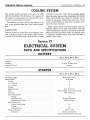
COOLING SYSTEM
The cooling system servicing is the same for 1959
with the exception of the following: The capacity of
the radiator cooling system is 17 quarts with a heater and 16 quarts without a heater.
The radiator oil cooler located in the bottom of the
pan in the radiator tank has a new service procedure.
Testing for Leaks
Remove the two oil cooler lines at the radiator. Connect a pressure gauge to one cooler outlet. Connect
a source of air pressure with a shut-off valve (closed
position) to the other outlet. Do not use pipe sealers
since the sealer may get into transmission oil circuit.
Open valve slightly and admit air pressure not to
exceed 50 psi gauge reading, then close valve. If the
cooler and all fittings are leak proof, the gauge reading will remain constant.
When a leak is detected, remove radiator from car.
Remove radiator lower tank (soft solder). Test the
cooler with 50 psi air pressure in water to locate leak.
Repair the leak using silver solder. If necessary, have
a competent radiator repair shop repair the leak or
install a new cooler.
Section VI
ELECTRICAL SYSTEM
DATA AND SPECIFICATIONS
BATTERY
MG-1, MG-2, MG-3, MY-1
Voltage
Capacity
Terminal Ground
12
78 Plate 70 Amp Hour
Negative
STARTER
MC-1, MC-2, MC-3, MY-1
Car Model Usage
Starter Model
Voltage
No. of Fields
No. of Poles
Brushes
Spring Tension
Drive
End Play
Free Running Test
Voltage
Amperage Draw
Minimum Speed rpm
Stall Torque Test
Torque Foot-Pounds
Voltage
Amperage Draw
Pinion to Housing
Clearance
„
MDT-6002-1770712
MDT-6002
12
4
4
4
32 to 48 Ounces
Solenoid Shift Overrunning Clutch
.005" Minimum
11
80 Amps Minimum
3800 Minimum
8.5
4
350
.070" to .120"
Between Pinion Stop
(with Armature End Play removed)
28—ELECTRICAL SYSTEM
CHRYSLER SERVICE MANUAL
STARTER (Cont'd)
Solenoid Switch
Pull-in Coil
Hold-in Coil
28.6 to 32.9 Amps at 6 Volts
10.2 to 11.8 Amps at 6 Volts
LIGHT BULBS
Headlights Inner (High Beam Only)
Headlights Outer (High and Low Beam)
Headlight Beam Indicator Light
Parking and Front Turn Signal
Rear Tail, Stop and Turn Signal Light
License Plate Light
Glove Box Light
Instrument Lights
Map Light
Turn Signal Indicator Light
Dome Light
Hand Brake Warning Light
Back Up Light
Transmission Push Button Light
Radio Dial Light
Clock Light
Trunk Light
Number
Required
Mazda
Number
C.P. or
Watts
Chrysler
Part No.
2
2
1
2
2
2
1
4
1
2
1 or 2
1
2
1
2
1
1
4001
4002
37J^ W
50-37^ W
2
32-4
32-4
3
2
2
15
2
15
6
32
2
1753435
1753436
127934
151567
151567
142450
127934
127934
151578
127934
151578
142453
142456
127934
2
15
127934
151577
57
1034
1034
67
57
57
1004
57
1004
90
1073
57
1891
57
1003
CIRCUIT PROTECTORS
Type
Rated Capacity
Location
Lighting System
Clock
Windshield Wiper
Radio
Dome Lamp
Window Lifts
Circuit Breaker
Fuse
Circuit Breaker
Fuse
Fuse
Circuit Breaker
22J^ Ampere
1 Ampere
6 Ampere
7*^ Ampere
6 Ampere
20 Amp-30 Amp
Back-Up Light
Cigar Lighter
Six-Way Seat
Fuse
Fuse
Circuit Breaker
6 Ampere
14 Ampere
40 Ampere
Rear Defroster
Heater
Air Conditioner (front)
Air Conditioner (rear)
Air Conditioner (dual)
Fuse
Circuit Breaker
Circuit Breaker
Circuit Breaker
Circuit Breaker
6 Ampere
20 Ampere
30 Ampere
20 Ampere
30 Ampere
Integral with Headlight Switch
At Fuse Block*
At Fuse Block*
At Fuse Block*
At Fuse Block*
At Terminal Block
Behind Left Front Kick Panel
At Fuse Block*
At Fuse Block*
At Terminal Block
Behind Left Front Kick Panel
At Fuse Block*
At Fuse Block*
At Fuse Block*
At Fuse Block*
At Fuse Block*
Circuit
*Fuse block is located at instrument panel (driver's compartment) to the left of radio.
GENERATORS
Gar Model
MC-1
MC-2, MC-3
MY-1
GJM-8001A; 1842801
GJM-8001A; 1842801
GHM-8005A; 1842778
With Air Conditioning
Front Unit Only
GJM-8001A; 1842801
GJM-8002A; 1842797
GHM-8001A; 1842774
Dual Air Conditioning
Front and Rear
GHM-8005B; 1889400
GHM-8001A; 1842774
GHM-8001A; 1842774
GHM-8005A; 1842778
GHM-8005A; 1842778
GGA-6003E; 1842603
GGA-6003E; 1842603
GGA-6001N; 1658863
GGA-6001N; 1658863
Generator Model
Standard
Gas Heater
Heavy Duty
GGA-6003E; 1842603
Heavy Duty True-Level Torsion Aire..
Generator Model
GGA-6001N
GGA-6003E
GHM-8001A
GHM-8005A
GHM-8006B
GJM-8001A
GJM-8002A
Rotation
Clockwise at
Drive End
Clockwise at
Drive End
Clockwise at
Drive End
Clockwise at
Drive End
Clockwise at
Drive End
Voltage
12
12
12
12
12
40 Amperes
30 Amperes
30 Amperes
35 Amperes
35 Amperes
Vibrating Regulator
Vibrating Regulator
Vibrating Regulator
Vibrating Regulator
Vibrating Regulator
Negative
Negative
Negative
Negative
Negative
2
2
2
2
2
2
2
2
2
2
34 to 41 ounces
35 to 53 ounces
35 to 53 ounces
18 to 36 ounces
18 to 36 ounces
Ball—Both Ends
Ball—Both Ends
Ball & Sleeve
Ball & Sleeve
Ball—Both Ends
Rated Output
Control
Ground Polarity
Poles
'..
Brushes
Brush Spring Tension
Bearings
/
/
.003"-.010"
.003"-.010"
.003"-.010"
.003' -.010'
.003"-.010"
Field Coil Draw (Arm. to field term.)
1.2 to 1.3 Amps
at 10 Volts
1.2 to 1.3 Amps
at 10 Volts
1.2 to 1.3 Amps
at 10 Volts
1.4 to 1.7 Amps
at 10 Volts
1.6 to 1.7 Amps
at 10 Volts
Motoring Draw
2.9 to 3.4 Amps
at 10 Volts
3.3 to 3.8 Amps
at 10 Volts
3.3 to 3.8 Amps
at 10 Volts
3.8 to 4.3 Amps
at 10 Volts
3.8 to 4.3 Amps
at 10 Volts
10 Amps, 13.4 Volts
at 1020 max. rpm
40 Amps, 15 Volts
at 1800 max. rpm
10 Amps, 13.5 Volts
at 1040 max. rpm
30 Amps, 15 Volts
at 1800 max. rpm
10 Amps, 13.5 Volts
at 1040 max. rpm
30 Amps, 15 Volts
at 1800 max. rpm
10 Amps, 13.4 Volts
at 1480 max. rpm
35 Amps, 15 Volts
at 2400 max. rpm
10 Amps, 13.4 Volts
at 1480 max. rpm
35 Amps, 15 Volts
at 2400 max. rpm
End Play
Output Tests (at 70° F.)
30—ELECTRICAL SYSTEM
CHRYSLER SERVICE MANUAL
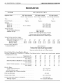
REGULATOR
MC-1, MC-2, MC-3, MY-1
Car Model
Regulator Model
VRX-6301A-1842798
(For 35 Amp Generators)
VRX-6201A-1642333
(For 30 Amp Generators)
VAT-6201-1662137
(For 40 Amp Generators)
12
12
12
Negative
Negative
Negative
Volts
Ground Polarity
Resistors
Marked 60..
Marked 38..
Marked 30..
55.0 to 70.0 ohms
34.5 to 42.0 ohms
28.0 to 34.5 ohms
34.5 to 45 ohms
Voltage Regulator
Voltage Winding Resistance.
Armature Air Gap
44.0 to 49.0 ohms
.048 to .052 inch
Contacts closed with high limit gauge installed.
Contacts open with low limit gauge installed.
Gauge on contact side and next to brass stop pin.
Voltage Setting (operating voltage)
After 15 minutes run at 7 amperes
Temperature in degrees F
50°
Maximum Setting
15.04
Minimum Setting
14.42
Current Limiting Regulator
Armature Air Gap
60°
70°
80°
90°
14.97
14.36
14.90
14.30
14.83
14.23
14.76
14.16
100°
14.69
14.09
110°
14.01
14.62
120°
14.54
13.94
.048 to .052 inch
Contacts closed with high limit gauge installed.
Contacts open with low limit gauge installed.
Gauge on contact side and next to brass stop pin.
Current Setting (After voltage Regulator Setting)
Operating Amperage after 15 minutes at 7 amperes. Then followed with a 15 minute run at rated current regulator
setting below 13.5 volts).
Temperature ( F ) . . . .
50°
60c
80°
90°
70°
100°
Model VRX-6201A (1642333) 30 Amp. Max. Setting. .. .
35
33
32
31
30
29
Min. Setting
31
29
27
28
26
25
Model VRX-6301A (1842798) 35 Amp. Max. Setting. . . .
Min. Setting....
39
35
38
34
37
33
36
32
35
31
34
30
Model VAT-6201 (1662137)
46
42
45
41
44
40
43
39
42
38
41
37
40 Amp. Max. Setting....
Min. Setting....
Cut-Out Relay:
Voltage Winding Resistance
Air Gap (contacts open)
(Measure gap as near to hinge as possible)
107 to 121 ohms
.031 to .034 inch
Point Gap (Minimum)
.015 inch
Contacts Close (Volts)
12.6 to 13.6 Volts
Contacts Open (after charge of 10 amperes)
Discharge Amperes
8.2 to 9.3 Volts
0 to 6 amperes (discharge)
ELECTRICAL SYSTEM—31
CHRYSLER SERVICE MANUAL
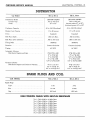
DISTRIBUTOR
MC-1, MG-2
MC-3, MY-1
IBP-4006-1842804
.015 to .018 inch
27° to 32°
IBS-4010A-1842805
.015 to .018 inch
(one set points 27° to 32°)
Car Model
Distributor Model....
Contact Gap
Dwell
(both sets points 34° to 40°)
.25 to .285 Microfarad
Condenser Capacity
17 to 20 ounces
Breaker Arm Tension
.25 to .285 Microfarad
17 to 20 ounces
Camshaft
Drive
Side Play (shaft)
.005 inch Max.
End Play (after assembly)
.003 to .010 inch
Camshaft
.005 inch Max.
.003 to .010 inch
18436572
Firing Order
Counter-clockwise
Rotation
18436572
Counter-clockwise
10° BTC
Timing
Automatic Advance
Distributor Degrees and rpm.
Vacuum Advance
Distributor Degrees and Inches of Vacuum
10° BTC
0°@ 270 to 540
0° to2°@ 540
2° to4°@ 800
4° to6°@ 1500
6.5° to 8.5° @ 2350
0°@310to490
0° to 2° @ 490
3.5° to 5.5° @ 800
6°to8°@ 1550
8.5° to 10.5° @ 2300
0° to 7.2 to 9.1"
4.5° to 7.5° @ 12"
9.5° to 12.5° @ 16.5"
0°@7.5to9.1"
6.0° to 9° @ 13"
11.5° to 14.5°© 18.2"
SPARK PLUGS AND COIL
CAR MODEL
MC-1, MC-2
MC-3, MY-1
Type
A-42
A-42
Size
14 mm
14 mm
.035 inch
.035 inch
Spark Plugs
Gap...
HIGH TENSION CABLES WITH BUILT-IN RESISTANCE
No. 1 Cable
No. 2 Cable
No. 3 Cable
No. 4 Cable
No. 5 Cable
No. 6 Cable
No. 7 Cable
No. 8 Cable
8,300 to
5,500 to
8,100 to
6,000 to
8,800 to
6,300 to
9,400 to
7,200 to
16,600 Ohms
11,000 Ohms
16,200 Ohms
12,000 Ohms
17,600 Ohms
12,600 Ohms
18,800 Ohms
14,400 Ohms
32—ELECTRICAL SYSTEM
CHRYSLER SERVICE MANUAL
SPARK PLUGS AND COIL (Cont'd)
CAR MODEL
MC-1, MC-2, MC-3, MY-1
Model
Ballast Resistor
Amperes
Engine Stopped
Engine Idling
CAH-4001
PU-5001
Coil
3.1 Amperes
2.5 Amperes
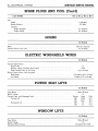
HORNS
All Models
Make
Current draw at 12.4 volts
Auto-Lite, Spartan
9 to 10 amps
ELECTRIC WINDSHIELD WIPER
All Models
Variable Speed Motor
Rated Volts.
Resistor (ohms) (Variable speed wiper)
Field Current Draw at 13.5 volts
Motor Current Draw (with dry glass)
High Speed
Low Speed
.
12
17-40
13^ to 2 amps
1 j/£ amps at 66 to 75 rpm
3 amps at 35 to 40 rpm
POWER SEAT LIFTS
All Models
Type Motor
Rated Voltage
Current Draw with Passenger Load
Vertical Lift
Series Wound
12
Pounds
Amps
500
50-60
200
40-45
600
60
150
35
Horizontal Lift
Volts
10.5
10.6
10.4
11.0
WINDOW LIFTS
All Models
Type Motor
Rated Voltage
Maximum Stall Current
Series Wound
12
25 amps at 8.9 volts
CHRYSLER SERVICE MANUAL
ELECTRICAL SYSTEM—33
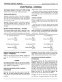
ELECTRICAL SYSTEM
Servicing the electrical system for the 1959 Chrysler
and Imperial Models is the same as for the 1958
models with the following added information.
SPEEDOMETER REMOVAL
Chrysler—Disconnect battery. Disconnect speedometer cable housing. Remove the two nuts and washers
from the rear of the speedometer. Slide speedometer
out the rear of panel.
Imperial—Disconnect battery. Disconnect speedometer cable housing. Remove 7 screws from the rear
of speedometer and pull out speedometer from rear
of panel.
SIX-WAY ELECTRIC POWER SEAT — OPTIONAL
The six-way electric power seat is driven by a twoway electric motor which operates through a solenoid and clutch assembly that supplies power through
flexible cables to slave units located in the seat tracks.
The control switch is located on the left side of the
front seat and is wired through relay to a 40 amp
circuit breaker which is located behind the left front
kick panel.
CONTROL CIRCUITS
Power is supplied to the motor relay from the circuit
breaker. Three wires go to the switch from the motor relay.
One wire (red) is used for power and two wires
(white and blue) are used for directional control of
the motor.
Three additional wires go from the switch (yellow,
green and brown) to the solenoid and clutch assembly which control movement of front, rear and horizontal risers. (See chart below.)
For Forward Tilt
For Forward Horizontal
[Red
[Red
For Straight Up
fRed
Connect Wires<j White
[Green
Connect Wires*) White
[Yellow
Connect Wires J White
I Yellow
[Brown
For Rearward Horizontal
For Rearward Tilt
For Straight Down
fRed
Connect Wires^j Blue
Green
fRed
Connect Wires^j White
[Brown
REMOVAL AND INSTALLATION OF FLEXIBLE
CABLES — POWER SEAT
Refer to the Chrysler Service Manual D-16350 for
removing and installing the power seat flexible cables.
CAUTION:
Seat guides should be in the up and forward position
when installing cables. Make sure guides are at the
same position (in alignment).
REMOVAL AND INSTALLATION OF MOTOR —
POWER SEATS
Removal—Disconnect the motor wires at relay. Remove the two nuts holding the motor to the drive
unit. Remove the motor from drive unit and rubber
coupling.
[Red
Connect Wires j Blue
I Yellow
[Brown
Installation—Install rubber coupling on motor shaft.
Align rubber coupling with the slot on the slave unit
shaft. Install motor and reconnect wires to relay.
DRIVE UNIT AND SOLENOID ASSEMBLY —
POWER SEATS
Disassembly—Remove the drive unit from the seat
assembly. Remove the two screws holding plate and
solenoids to the drive unit. Remove the plate and solenoid assembly. Be careful not to lose the three
springs under the solenoid when removing the solenoid coils. Bend back the tabs of the solenoid cover.
Unsolder the coil ground wire at the cover tab. Remove the cover from the coil. Remove the screws
holding the cover on the drive unit. Remove the
cover and lift out the clutch lever and shaft.
Assembly—Install the clutch lever and shaft. Make
sure the lever is properly seated on the drive collar.
GLOVE BOX SW.
RT. AUTO. DOOR
I
RT. PARK & T/SIG. LAMP
|
RADIO
LAMP
9*
18 YELLOW- 4
CA
181 YELLOW
p*<*
.RT. MAP LP.
-CIGAR LIGHTER
r
FUSE BLOCK
•-C/LITER
-DOME
CLOCK
18 ORANGE
IGNITION DISTRIBUTOR
WIPER MOTOR
RT.
DUAL HEADLAMP
OIL GAUGE
FUEL GAUGE
,RT. T/SIG. LP.
18 WHITE-
SP. EQ. HORN
t=Q
••RR. A / C
-RADIO
*B/UP LP
RR. DEFR
IGNITION COIL
COIL RESISTOR
LUE
RADIO CONDENSER
18D
-2I T/SIG. SW.
DISCONNECT
HORNS
TEMP. GAUGE
SENDING UNIT
16 DK. GREEN
LT.
DUAL HEADLAMPS
LAMP^
TO HORN
BUTTON
ITCH-
REAR W I N D O W
DEFROSTER SW.
NOTE: 18-BLACK CIRCUIT
WITHOUT POWER STEERING
18 VIOLET
GENERATOR
0«
12 RED
16 B R O W N -
SER
LT. MAP LP.
HI BEAM IND. LP.
CLOCK LP.
HANDBRAKE IND. LAMP
LT. T/SIG. LP.
STARTER MOTOR &
STARTER SOLENOID
tfpPIp
12 BROWI
HORN RELAY
"18 TAN"
-16 RED-16 BLACK
18 YELLOW
18 LT. GREEN"
18 DK. GREEN
LT.
PARK & T/SIG. LAMP
BATTERY
— 1 8 BLACK18 DK. BLUE
REAR OF FRONT SEAT
CIGAR LIGHTER MC3
4 DR. SEDAN 4 DR. HT.
4 DR. SUB.
PUSH
BUTTON
"GEAR
SHIFT LP.
VIOIET_ 1 0 RED
fT8 PINK
I—LJ 18 VifrlTE
STARTEI
r-18 YELLOW-
RELAY
18 LT.
t — 1 2 BLACK
GRD.
BATT.
GENERATOR REGULATOR/GRD. A R M
NEUTRAL SAFETY SWITCH
BLUE
BACK UP LP. SW.
LT. AUTO. DOOR SWITCH
-18 BLACK-^
¥***
SIGNAL LAMP SWITCH
14 LT. GREEN-
TAN TO W/LIFT SW.
TO SEAT ADJ. SW.
59x58
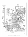
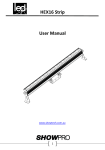
Fig. 30 — Chassis and Instrument Panel Wiring Diagram — Models M C - 1 , 2 and 3
A / C & HTR.
RR. A / C
RADIO
REAR WINDOW
RT. PARK & T/SIG. LAMP
RT. DOOR SW.
IGNITION DISTRIBUTOR
"YELLOW
GLOVE BOX
LAMP MAP
SWIT
2 4 6 8
SPARK PLUGS
1 3
5 7,
INSTRUMENT PANEL
R
REAR SHELF PANEL
IGNITION COIL
COIL RESISTOR
16
BLUE
TRIAD HORN
REAR W I N D O W
DEFROSTER MOTOR
RADIO CONDENSER
TURN SIG.
..AUTO. SW
TURN
SIG.
AUTO.
SW.
TEMPERATURE GAUGE
TURN SIGNAL RELAY
LT. f'/SIG. LP.
LT. PARK &
r/SIG. LAMP
DO.
16 LT. GREEN
ROWN-0*-IB— I
NEUTRAL
ROWN
SAFETY
12BLXCK SWITCH
FOOT DIMMER
SWITCH
HAND BRAKE
AD.,
ARM
- LAMP FLASHER
BATT.
W I N D O W LIFT,
RD
„ '
SEAT ADJUSTER
ELD
CIGAR LIGHTER
CIRCUIT BREAKERS
MYI-L CLOTH TRIM 4
1 REQ'D. 2 REQ'D
LEATHER TRIM
14 LT. GR
LAMP
BUTTON
R SHIFT LP.
w/s
WASHER
SWITCH
16 YELLOW
6 RED
BLUE
6 BLACK
MANUAL T/SIG.
CANCELING SW
- 1 8 BRO
HAND BRAKE SW.
•TO REAR SEAT
CIGAR LIGHTER
LT. DOOR SW.
FO SEAT ADJ.
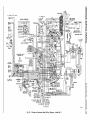
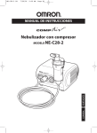
Fig. 31 —Chassis and Instrument Panel Wiring Diagram — Model MY-1
59x59
36—ELECTRICAL SYSTEM
CHRYSLER SERVICE MANUAL
^ ^ - - - R T . RR. SW. & MTR
fff—
GRAY-*
GRAY-foj
RT. FRT. SW. &
PINK
- 1 4 YELLOW
LOCK RELAY
14 VIOLET
rtsJ
•VIOLET-L-T
14
DK. G R E E N L
14 WHITE
PINK
14 VIOLET-
GRAY-
RT. FRT. DOOR LOCK SW
14 WHITE16 ORANGE-pn—UNLOCK
12 LT. BLUE+M—FEED
16 PINK
1£*—LOCK
12 ORANGE
14 LT. GREEN
RT. FRT. DOOR LOCK SOLENOID
RT. RR. DOOR
LOCK SOLENOID
RT. RR. CIGAR LIGHTER
BATTERY
LT. RR. CIGAR LIGHTER
LT. RR. DOOR
LOCK SOLENOID
14 LT. GREENC/LITER C/B 8 AMP.
S/ADJ. C/B 40 AMP
W/L C/B. 30 AMP.
12-LT. BLUE CIRCUIT GOES
TO W/LIFT C/B O N 4 D'RS
& C/LT'R. C/B O N 2 D'RS.
ORANGE
LT. FRT. DOOR LOCK SOLENOID
LT. FRT. DOOR LOCK SW.
14 DK. BLUE
p
[_
14 BROWN-|o f>T
LT. FRT. DR. MASTER SW. & MTR.
BLACKORANGE-
ff=]
rty
\T.
J
ORANGE
ORANGEF~~|
RED
RR. DR.
SW.
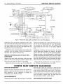
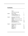
Fig. 32 — Window Lifts, Cigar Lighter and Electric Door Locks Wiring Diagram
Install the cover and screws. Install the coil in the
coil cover with the coil ground wire next to one of
the tabs. Position the cover tabs in the slots on the
coil plate. Bend over the tabs and solder the coil
ground wire to the tab and plate.
Install the three solenoid springs and position the
solenoids over the springs. Fasten the solenoids to
the drive unit. Install the drive unit.
REMOVAL AND INSTALLATION OF SLAVE UNIT —
POWER SEATS
Remove the drive unit and cables. With the seat
guide in the up and forward position, remove the
long clevis pin from the front of the guide.
Remove the front rack clevis pin. To facilitate the
removal of the slave unit, remove the slave unit cap.
Do not lose the springs under the cap. The springs
are between the racks and slave cap. Remove the
nuts holding the slave unit to the guide. Remove
unit.
Installation—Position the slave unit over the studs
on the guide base. Position the racks in the slave
unit so they will be in the up and forward position.
Fasten the racks to the guide assembly. Position the
springs on the rack and install slave unit cap. Install
the slave unit mounting nuts. Install the front guide
clevis pin. Install cables in slots and check the operation of power seats. Install drive unit and cables.
Figures 30, 31 and 32 show new wiring diagrams
for Chrysler and Imperial cars for 1959.
POWER SEAT SERVICE DIAGNOSIS
ENTIRE UNIT INOPERATIVE
Remove all wires from seat switch and connect together as shown in the chart for the six various controls operations, if the operation is normal, by
connecting wires. Replace switch.
MOTOR INOPERATIVE
Check red wire at relay with test light. If test light
does not light, check for continuity in #10 red feed
wire, faulty circuit breaker or poor connection between circuit breaker and starter relay. If test light
lights, connect #10 red feed wire with red and black
or red and green wires from motor. If motor runs,
relay was faulty, replace relay. If motor does not
run, the motor is faulty, replace motor.
SEAT INOPERATIVE (MOTOR RUNS)
CHRYSLER SERVICE MANUAL
Jump wire from #10 feed wire to each solenoid
terminal on clutch assembly. Solenoids should each
"click" as jumper is connected. If solenoid does not
click:
ELECTRICAL SYSTEM—37
(e) Remove horizontal stops located on slide at
(D).
(a) Check wire in harness for open circuit. Repair.
(f) Separate seat slide (C) from base (N) by
pressing slide rearward which will allow rollers (A)
to jump retaining rivets (E, F, G, H) thereby separating slide from base.
(b) Possible seized solenoid armature in coil. Replace coil.
(g) Remove rivet (F) and replace with 5/16-18
x 1/2" cap screw (1) to retain proper position.
(c) Possible burned-out solenoid. Replace solenoid.
SEAT INOPERATIVE (MOTOR RUNS &
SOLENOIDS CLICK)
Check drive unit for stripped or broken gear. Replace drive unit if necessary.
SLAVE UNIT INOPERATIVE
(MOTOR, SOLENOIDS & DRIVE UNIT O. K.)
Check for broken drive cable and replace as necessary.
NOTE: A frayed drive cable may be repaired by
applying light coating of solder and then grinding to
cable size.
SEAT TRACK EXCESSIVELY LOOSE
Due to loose rivet joints.
(a) Disassemble upper track seat support (B) by
removing cotter keys and pins.
(b) Remove seat support and tighten all riveted
joints (J) by peening with a ball peen hammer.
SEAT HAS ROCKING MOTION
LOOSE FRONT LEVERS
Excessive movement between slide and base of track
assembly. This condition is possible due to roller
being out of position.
Arc weld front levers (K) to prevent movement between the two sections comprising the front lever assembly.
(a) Remove power seat assembly from vehicle.
(b) Remove seat drive tubes from slave unit.
CAUTION:
Do not run motor with drive cables and tubes disassembled or unit will be placed out of synchronization.
(c) Remove seat support (B).
(d) Remove seat slave unit from seat track slide
(C).
SEAT CHUCK FORE AND AFT
Due to loose horizontal rack support arm to lower
track base.
(a) Remove seat track assembly from vehicle and
arc weld.
(b) Tighten rack attaching pins (M) by arc welding.
(c) Check for loose horizontal rack in slave unit
gear train. If loose, replace slave unit.
RESISTANCE TYPE SPARK PLUG CABLES
All 1959 Chrysler and Imperial engines incorporate
conventional spark plugs (without resistors), along
with resistance type spark plug cables to eliminate
radio interference.
For identification purposes, this new cable has
"RADIO" printed on it.
The new cable uses a graphite or composition type
conducting core replacing the copper wire found in
the center of conventional spark plug cable. Full
contact is made between the core and terminals by
means of a short wire pin pushed into the ends of
the cable.
Precautions must be observed in handling to prevent damage to the core. The cable should be removed from the spark plug by grasping the cable
cover and pulling straight off with a steady, even
38—ELECTRIGAL SYSTEM
CHRYSLER SERVICE MANUAL
pull. Pulling sideways could jam the terminal on the
spark plug and cause the cable to separate from the
terminal. The cable terminal should not be crimped
to the point that excessive force is required to remove it from the spark plug.
The cables should never be removed by giving
them a quick jerk. Doing so can stretch the core and
cause a high resistance or open circuit. If a damaged
core is suspected, a resistance check with an ohmmeter should be made. The resistance of the various
plug cables will vary because of the different lengths,
see chart below:
SPARK PLUG CABLES WITH
BUILT-IN RESISTANCE
No.
No.
No.
No.
No.
No.
No.
No.
1 Cable
2 Cable
3 Cable
4 Cable
5 Cable
6 Cable
7 Cable
8 Cable
8,300
5,500
8,100
6,000
8,800
6,300
9,400
7,200
to
to
to
to
to
to
to
to
16,600
11,000
16,200
12,000
17,600
12,600
18,800
14,400
Ohms
Ohms
Ohms
Ohms
Ohms
Ohms
Ohms
Ohms
If any cable has appreciably more resistance than
specified, check to be sure the terminals are in contact with the pin and the pins is in full contact with
the core. If the terminals and pins are properly installed and the cable resistance is still more than
specified, the cable should be replaced with a new
resistance type cable.
A new terminal should never be attached to the
resistance core cables unless the wire pin is in place;
otherwise, contact will not be maintained with the
core. This will result in arcing and burning of the
core which will cause engine malfunctioning and
radio interference.
CAUTION
Resistor type spark plugs are never to be used with
the new resistance type cable. The added resistance
of the spark plugs may cause malfunctioning of the
ignition system. When replacing a spark plug, be
sure to use the correct type specified for the particular engine.
SERVICE DIAGNOSIS
If the radio develops excessive noise or if there is a
pronounced engine miss, check for faulty or broken
cables.
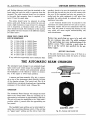
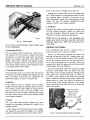
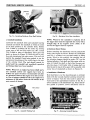
THE AUTOMATIC BEAM CHANGER
The automatic beam changer is an automatic headlight control unit which senses the headlight intensity from other vehicles and automatically adjusts
the headlights (of the vehicle in which it is mounted,) to the upper or lower beam position.
A scanner and base assembly (Fig. 33), is mounted on top of the instrument panel, directly in front
of the steering column. The control unit Fig. 33 is
mounted on a convenient structural part (grounding
purposes) of the vehicle's body. (Figure 34).
A0JUSTIN8 KNOB
—LOCKING-SCREW
SCANNER
OPERATION
The Automatic Beam Changer will change the headlight to the "lower beam" when an oncoming car is
approached at a distance of approximately 1200 feet.
The unit will reset the headlights to the "high beam"
position within 1/2 second after the approaching car
has passed.
The headlight beam setting can be interrupted by
using the conventional dimmer switch. If the unit has
an "upper beam" setting and the driver feels that
CONTROL UNIT
Fig. 33 — Scanner and Control Unit
CHRYSLER SERVICE MANUAL
ELECTRICAL SYSTEM—39
"SCANNER"
INSTRUMENT
PANEL
the "lower beam" is required, he can override the
automatic control by depressing the dimmer switch
to obtain the "lower beam" condition, Automatic operation is restored when the driver again depresses
the dimmer switch.
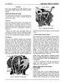
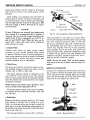
DRIVER ADJUSTMENTS
A knob, located at the rear of the scanner unit (Fig.
33), provides a sensitivity adjustment. If the headlights do not change beam quickly enough upon approaching another car, it is an indication that sensitivity is set too low and correction is made by turning
the scanner knob clockwise (to the right).
Fig. 34 — Location of Beam Changer Control Unit
If the headlights "change beam" too soon, the sensitivity can be decreased by turning the scanner knob
counter-clockwise (to the left).
AIMING THE AUTOMATIC BEAM CHANGER
PRE-AIMING INSTRUCTIONS
Before attempting to aim the automatic beam changer, complete the following pre-aiming instructions.
Place vehicle on a level floor.
If the vehicle is placed in an area in which the
floor is not level, it will be necessary to take this
condition into consideration when "aiming" the
"scanner" unit. Refer to aiming the "scanner"
unit.
Check front spring height. Adjust to specifications
—if necessary.
Check tire inflation. Tire pressure should not vary
more than 3-5 pounds among tires.
Rock vehicle sideways to allow spring shackles,
et cetera to assume a normal position.
33) just enough to permit free movement of the
"scanner" through its arc, as controlled by the
mounting base. (Total angular deflection of the
"scanner" unit is six degrees).
Using headlamp aimer kit, Tool C-3674, use the
split image transit and target assembly to determine
slope of floor, as outlined in the directions contained
in the aimer kit.
Move "scanner" forward or backwards on base
(through arc) to bring the leading edge of the bubble of "scanner" aimer, Tool C-3697, in alignment
with the proper "plus" or "minus" value (on level
dial) which was obtained from the transit of aimer
kit, Tool C-3674.
Example: If transit indicates that a minus 2 correction for slope is necessary, bring leading edge, of
bubble of aimer Tool, C-3697, to the minus 2 index
If gasoline tank is not full, place a 100 pound
weight in trunk of vehicle.
There should be no other load in the vehicle, other
than the driver.
TOOL
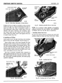
AIMING THE "SCANNER" UNIT
Vertical alignment of the "scanner" unit is critical.
Mount "scanner" aimer, Tool C-3697, on the "scanner" unit, as shown in Figure 35. Make sure that all
conditions listed under "pre-aiming instructions"
have been performed, before proceeding with the
aiming operation.
Loosen the cross-recess head locking screw (Fig.
"SCANNER'
BASE
LOCKING
SCREW
Fig. 35 — Mounting Scanner Aimer Tool
40—ELECTRICAL SYSTEM
line. (Figure 35). Tighten locking screw (Fig. 33)
securely and then recheck position of bubble. If position of bubble has changed, loosen locking screw
CHRYSLER SERVICE MANUAL
slightly and make necessary correction to bring bubble once more into desired position. Retighten locking screw securely and remove "scanner" aimer Tool.
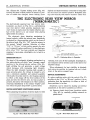
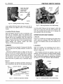
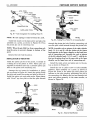
THE ELECTRONIC REAR VIEW MIRROR
("MIRROR-MATIC")
The electronically operated rear view mirror (mirror-matic), as shown in Fig. 36 is a self-dimming
rear view mirror which provides maximum rearward vision at night, since the bright reflection surface of the mirror is in use except when glaring
light strikes its surface.
The electronic glare detecting mechanism is
housed entirely within the mirror case. Sensitivity
is selected by a three-position switch on the front of
the mirror bezel (Fig. 36). "Off" locks the mirror in
the normal "bright" position. Selection of either
"City" or "Hi-way" switch position permits the mirror to respond to glare conditions. It is less light-sensitive when "City" has been selected and therefore
response to neon signs, streetlights, etc. is held to a
minimum.
OPERATION (FIG. 37)
The heart of the automatic tripping mechanism is a
tiny photo-electric cell which "sees" through a small
aperture in the silvered mirror surface (Fig. 36).
Light striking the cell generates a small voltage
which increases with increasing light intensity.
When the light intensity becomes high enough to
cause annoying glare, the voltage is enough to activate a miniature amplifier and solenoid assembly
which pulls the prism mirror a few degrees upward
to reflect a dim image off the front surface of the
glass and into the driver's eyes. As long as glare is
present, the mirror will remain in its "dim" position,
returning immediately to its normal "bright" position when the glare drops below a pre-set level.
DRIVER ADJUSTMENT (POSITIONING MIRROR)
When adjusting the position of mirror-matic for best
LIGHT-SENSITIVE CELL
SILVERED MIRROR
/
SURFACE
BRIGHT REFLECTION
I BRIGHT
\ LIGHT
1
RAYS
NON-GLARE
DIM REFLECTION
FRONT SURFACE
OF MIRROR
"OFF"
POSITION
"CITY" OR "HI-WAY" POSITION
MIRROR-MATIC ELECTRONIC REARVIEW MIRROR
Fig. 37 — Positioning Mirror in Operation
visibility, first turn off the headlights (headlight circuit energizes mirror system) and set the mirror for
brightest image.
When adjustment for best visibility is obtained,
lock mirror -in position by turning lock nut (clockwise) at the mirror support base.
SERVICE ADJUSTMENTS
If a glare condition exists with the switch (Fig. 37)
set either in the "City" or "Hi-way" position, it is an
indication that the sensitivity in either or both of
these positions is too low.
Sensitivity can be raised by making an internal
adjustment at the mirror assembly as follows:
(a) Remove plastic knob from 3-position switch
(Fig. 36) by carefully pulling outward on
plastic knob.
LIGHT SENSITIVE
CELL
POTENTIOMETERS
Fig. 36 — Mirror-Matte Rear View Mirror
Fig. 38 — Mirror-Matic Back Cover
CHRYSLER SERVICE MANUAL
ENGINE—41
(b) Remove the two screws and remove bezel by
lifting bezel outward and upward (to clear
metal retaining tabs).
(c) Expose internal mechanism of mirror assembly by lifting top portion of back cover upward (to clear metal retaining tabs) and
moving back cover rearward over mirror support. Move back cover rearward only far
enough to provide access to potentiometer
adjusters (Fig. 38).
(d) To increase sensitivity of the "City" position,
turn the arm of the potentiometer marked
"City" in the direction indicated by the arrow.
(e) To increase sensitivity for "Hi-way" driving,
turn the arm of the potentiometer marked
"Hi-way" in the direction indicated by the
arrow.
NOTE: To decrease sensitivity of either or both the
potentiometers, turn potentiometer arms in the direction opposite to direction indicated by arrow.
(f) Replace back cover by positioning back cover
over the two metal tabs and aligning screw
holes in bottom of cover with threaded holes
in mirror support.
(g) Install bezel by aligning slots at top of bezel
with metal tabs and aligning screw holes in
bottom of bezel with threaded holes in mirror support replace screws (Fig. 36) and
tighten securely.
(h) Replace plastic switch knob.
(i) Adjust mirror to desired position and test
operation of unit.
Section VII
ENGINE
DATA AND SPECIFICATIONS
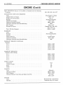
ENGINE
Type
Number of Cylinders
Bore—MC-1, MC-2
MC-3, MY-1
Stroke
Piston Displacement—MC-1, MC-2
MC-3, MY-1
Compression Ratio
Compression Pressure at 150 rpm (plugs removed) Wide Open Throttle
Maximum Variation Between Cylinders (any one engine)
Firing Order
CYLINDER NUMBERING
Left Bank
Right Bank
CRANKSHAFT
Type
Bearings
Journal Diameter
Crank Pin Diameter
Maximum Out-of-Round Permissible
Number Main Bearings
Diametral Clearance Desired
End Play
Thrust Taken By
Finish at Rear Seal Surface
Interchangeability of Bearings
90° V
8
4.031"
4.188"
3.750"
383 cu. in.
413 cu. in.
10.0 to 1
150 to 180 lbs.
25 lbs.
1-8-4-3-6-5-7-2
1-3-5-7
2-4-6-8
Fully Counter-Balanced
Steel Backed Babbitt
2.7495 to 2.7505"
2.374 to 2.375"
.001"
5
.0005 to .0015"
.002 to .007"
No. 3 Main Bearing
Diagonal Knurling
Upper Nos. 1, 2, 4, 5
Lower Nos. 1, 2, 4, 5
CHRYSLER SERVICE MANUAL
42—ENGINE
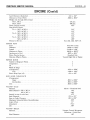
ENGINE (Cont'd)
MAIN BEARINGS (Service) All Available in Standard and the following
Undersizes
CONNECTING RODS AND BEARINGS
Type
Length (Center to Center)
Weight (less bearing shells)
Bearings
Diameter and Length
Diametral Clearance Desired
Maximum Allowable before Reconditioning
Side Clearance
Bearings for Service
.001, .002, .003, .010, .012"
Drop Forged " I " Beam
6.766—.770"
29.4 oz.
Steel-Backed Babbitt
2.375 x .927"
.0005 to .0015"
.0025"
.009 to .017"
Standard .001, .002, .003,
.010, .012" U.S.
1.0925 to 1.0928"
Piston Pin Bore Diameter
CAMSHAFT
Drive
Bearings
Number
Thrust Taken by
Diametral Clearance
Maximum Allowable before Reconditioning
Chain
Steel Backed Babbitt
5
Cylinder Block
.001 to .003"
.005"
CAMSHAFT BEARING JOURNALS
Diameter
No. 1
No. 2
No. 3
No. 4
No. 5
1.998 to
1.982 to
1.967 to
1.951 to
1.748 to
1.999"
1.983"
1.968"
1.952"
1.749"
CAMSHAFT BEARINGS
Diameter (after reaming)
No. 1
No. 2
No. 3
No. 4
No. 5
2.000 to
1.984 to
1.969 to
1.953 to
1.750 to
2.001"
1.985"
1.970"
1.954"
1.751"
TIMING CHAIN
Adjustment
Number of Links
Pitch
Width
TAPPETS
Type
Clearance in Block
Body Diameter
Clearance Between Valve Stem and Rocker Arm Pad
PISTONS
Type
Material
,
None
50
.50"
.88"
Hydraulic
.0005 to .0015"
.9040 to .9045"
Dry Lash
.060 to .210"
Horizontal Slot w/Steel Struts
Aluminum Alloy Tin Coated
CHRYSLER SERVICE MANUAL
ENGINE—43
ENGINE (Cont'd)
Land Clearance (diametral)
Clearance at Top of Skirt
Weight (std. through .040 oversize)
MC-1, MC-2
MC-3, MY-1
Piston Length (overall)
Ring Groove Depth
No. 1—MC-1 & MC-2
MC-3 & MY-1
No. 2—MC-1 &MC-2
MC-3 & MY-1
No. 3—MC-1 & MC-2
MC-3 & MY-1
Pistons for Service
PISTON PINS
Type
Diameter
Length
Clearance in Piston
Interference in Rod
Piston Pins for Service. . .
Direction Offset in Piston
.041 to .047"
.0005 to .0010"
724 gms.
780 gms.
3.95"
.213"
.216"
.213"
.216"
.195"
.200"
Std. .005, .020, .040" O.S.
Press Fit in Rod
1.0935 to 1.0937"
3.4440 to 3.450"
.00045 to .00075"
.0007 to .0012"
Standard Only
Toward Right Side of Engine
PISTON RINGS
Number of Rings per Piston.
Compression
Oil
Width of Rings
(Compression)
(Oil)
Piston Ring Gaps (all)
.0775 to .0780"
.1860 to .1865"
.013 to .025"
RING SIDE CLEARANCE
(Compression)
Upper
Intermediate
(Oil)
.0015 to .0030"
.0015 to .0030"
.0010 to .0030"
VALVES—Intake
Material
Head Diameter MC-1, MC-2
MC-3, MY-1
Length (to top of valve face)
Stem Diameter
Stem to Guide Clearance
Maximum Allowable Before Reconditioning.
Angle of Seat
Adjustment
Lift
VALVES—Exhaust
Material
Head Diameter.
3
2
1
Silicon—Chromium Steel
1.95"
2.08"
4.79"
.372 to .373"
.001 to .003"
.004"
45°
None
.389"
Nitrogen Treated Manganese
Chromium—Nickel Steel
1.60"
44—ENGINE
CHRYSLER SERVICE MANUAL
ENGINE (Cont'd)
Length (to top of valve face)
Stem Diameter
Stem to Guide Clearance
Maximum Allowable Before Reconditioning
Angle of Seat
Adjustment
Lift
4.79"
.371 to .372"
.002 to .004"
.006"
45°
None
.389"
VALVE SPRINGS
Number
Free Length
Load when Compressed to (valve closed)
Load when Compressed to (valve open)
Valve Springs I.D
16
2.34"
1.860" @ 95 —105 lbs.
1.470" @ 188—252 lbs.
1.010 to 1.030"
CYLINDER HEAD
Number Used
Combustion Chamber
Valve Seat Runout (maximum)
Intake Valve Seat Angle
Seat Width (finished)
Exhaust Valve Seat Angle
Seat Width (finished)
Cylinder Head Gasket Compressed (thickness)
2
Wedge Type
.002'
45C•o
.060 to .085"
45°
.040 to .060"
.022"
ENGINE LUBRICATION
Pump Type
Capacity (qts.)
Pump Drive
Operating Pressure at 40 to 50 mph
Pressure Drop Resulting from Clogged Filter
Rotary, Full Pressure
5*
Camshaft
45 to 70 lbs.
7 to 9 lbs.
*When Filter Element is Replaced, add 1 qt.
TIGHTENING REFERENCE
Torque
Foot-Pounds
Connecting Rod Nut—Plain
Connecting Rod Nut—CST (Black)
Cylinder Head Bolt
Main Bearing Cap Bolt
Spark Plug
Camshaft Lockbolt
Carburetor to Manifold Nut
Chain Case Cover Bolt
Torque Converter Housing Bolt
Clutch Housing Bolt
Crankshaft Rear Bearing Seal Retainer
Crankshaft Bolt
Cylinder Head Cover Stud and Nut
Distributor Vacuum Line Tube Nut
Distributor Clamp Bolt
45
40
70
85
30
35
7
15
30
30
30
135
40 in.-lbs.
95 in.-lbs.
15
Thread
Size
^8-24
^-24
%-14
J4-13
14 mr
%>—14
%-24
5
/i6-18
•HJ-16
^-16
%~1Q
%-W
J4-28
^-24
^ fi -18
ENGINE—45
CHRYSLER SERVICE MANUAL
TIGHTENING REFERENCE (Cont'd)
Engine Front Mounting to Frame Nut
Engine Front Mounting to Block Nut
Exhaust Manifold Bolt
Exhaust Pipe Flange Nut
Exhaust Pipe Clamp Bolt
Exhaust Pipe Support Clamp Bolt
Fan Attaching Bolt
Fan Belt Idler Pulley Nut
Fan Belt Idler Pulley Bracket Bolt
Flywheel Housing to Cylinder Block Bolt
Flywheel Housing Cover Bolt
Fuel Pump Attaching Bolt
Generator Bracket Bolt
Generator Mounting Nut
Generator Adjusting Strap Bolt
Generator Adjusting Strap Mounting Bolt
Intake Manifold Bolt
Manifold Heat Control Counterweight Bolt
Oil Pan Drain Plug
Oil Pan Bolt
Oil Pump Cover Bolt
Oil Pump Attaching Bolt
Oil Filter Attaching Stud
Rocker Shaft Bracket Bolt
Starter Mounting Bolt
Vibration Damper Bolt
Valve Tappet Cover End Bolt
Water Pump to Housing Bolt
Water Pump Housing to Cylinder Block Bolt
A/C Compressor to Engine Bolt
„
„
.
,
.
85
45
30
40
20
20
15-18
45
30
50
7
30
50
20
15
30
40
50 in.-lbs.
35
15
15
35
30
30
50
15
8
30
30
30
#10-32
56-16
ENGINE
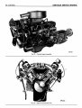
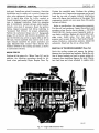
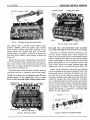
The new V-8 Engine, as shown in Figure 39, 40 and
41, ia one of the finest, most efficient engines to be
designed by Chrysler Engineering. It contains many
weight reducing features.
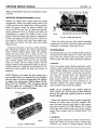
Some of the new features, as shown in Figures
42, 43 and 44, are in-line overhead valves, wedge
shaped combustion chambers, full length cylinder
water jackets, rigid crankshaft and series flow cooling system. In addition, the volume of coolant in the
engine has been reduced to improve engine warm
up. The ignition distributor is located at the upper
front end of the engine for easier servicing.
The lubrication system consists of an externally
mounted rotor type oil pump of greater capacity, full
flow oil filter and a series of passages where the oil
is delivered to the engine. The oil filter can be installed by hand.
The engine has 10:1 compression ratio, is equipped
with a dual carburetor on the Windsor Model
(MC-1), and a 4-barrel carburetor on all other models, and uses premium fuel. The engine has exceptional smoothness and performance throughout the
entire speed range.
MINOR TUNE UP
A periodic engine tune up will assure maximum engine performance and fuel economy. The following
procedures should be followed when performing
minor engine tune up.
Check battery specific gravity, add water if necessary and clean and tighten battery connections.
Clean and adjust the spark plugs (.035 inch gap).
Tighten to 30 foot-pounds torque with Tool C-3054.
Adjust the distributor contact points (.015 to .018
46—ENGINE
CHRYSLER SERVICE MANUAL
59x151
Fig. 39 — Chrysler Engine Assembly
59x54
Fig. 40 — Engine End Sectional View
ENGINE—47
CHRYSLER SERVICE MANUAL
inch gap). Install new points if necessary. Check the
distributor cap for cracks and corrosion,. Inspect the
rotor, rotor spring and plunger. Inspect the distributor to spark plug wires for brittle, cracked or
frayed insulation. Inspect small lead wires for tightness, or damaged insulation. Check for excessive
play in distributor vacuum advance plate bearing.
Install a new plate if necessary. Reset the ignition
timing. Inspect accessory belt drives referring to
"Accessory Belt Drives," for proper adjustments.
Tighten the carburetor flange nuts to 7 foot-pounds
torque. Set carburetor idle mixture adjustment. Adjust the throttle stop screw so engine idles at 450 to
500 rpm. Check manifold heat control valve in the
right exhaust manifold for proper operation and
apply Manifold Heat Control Valve Solvent Part
Number 1879318 to the bushing and shaft, as shown
in Lubrication Section.
MAJOR TUNE UP
Perform all the steps of a "Minor Tune Up" and in
addition, the following procedures should be followed when performing Major Engine Tune Up.
Tighten the manifold nuts. Perform the cylinder
compression test. Compression pressures can be read
from the top side of engine without interference
using a 30 degree bend extension on, the gauge. The
compression should not vary more than 25 pounds
between cylinders.
Refer to specifications for compression pressures.
Test the coil, and condenser. Inspect the primary and
secondary wires. Service the air cleaner — DO NOT
WASH OR OIL. Service more frequently under severe dusty conditions. Replace air cleaner filter cartridge every 15,000 miles. Test fuel pump for
pressure and vacuum. Refer to Fuel Section Specifications. Perform a combustion analysis. Adjust the
carburetor. Road test the car as a final check.
REMOVAL OF THE ENGINE ASSEMBLY (From Car)
Drain the cooling system and remove the battery.
Remove the fan shroud and radiator. Scribe the outline of hinge brackets on hood to assure proper adjustment when installing. Remove the hood. Disconnect fuel lines and wires attached to engine units.
58x135
Fig. 41 — Engine Side Sectional View
48—ENGINE
CHRYSLER SERVICE MANUAL
O>
ENGINE—49
CHRYSLER SERVICE MANUAL
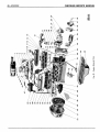
Fig. 42 — Engine External Parts
1.
2.
3.
4.
5.
6.
7.
8.
9.
10.
11.
12.
13.
14.
15.
16.
17.
Carburetor Air Cleaner
Coil
Vacuum Line
Wiring Harness (bracket)
Fuel Line
Tappet Chamber Cover and Intake
Manifold Gasket
Reinforcement, silencer and
Retainer
Wiring Harness (brackets)
Oil Filler Cap
Rocker Cover L
Rocker Cover Gasket L
Spark Plug Heat Shield
Cylinder Head L
Oil Level Indicator
Exhaust Manifold L
Oil Level Indicator Tube
Cylinder Head Gasket
18.
19.
20.
21.
22.
23.
24.
25.
26.
27.
28.
29.
30.
31.
32.
33.
34.
35.
36.
Distributor Clamp
Water Pump Housing Gasket
Oil Pump Housing Gasket
Outlet Elbow
Outlet Elbow Gasket
Thermostat
Temperature Sending Unit
Water Pump Housing
Water Pump Body Gasket
Water Pump Body
Hub
Water Pump Pulley
Bolt
Washer
Crankshaft Pulley
Vibration Damper
Oil Filter
Oil Pump
Chain Case Cover
37.
38.
39.
40.
41.
42.
43.
44.
45.
46.
47.
48.
49.
50.
51.
52.
53.
54.
55.
Remove the air cleaner and carburetor. Attach the
engine lifting fixture Tool C-3466 to carburetor
flange studs on the intake manifold and attach a
chain hoist to the fixture eyebolt. Disconnect the propeller shaft, wires and linkage at transmission. Disconnect exhaust pipes at manifolds. Be sure the
exhaust system is sufficiently supported while the engine is removed. Remove rear crossmember to transmission support attaching bolts.
NOTE: Place a roUaway jack under the transmission
56. Cylinder Head R
Chain Case Cover Gasket
57. Crankcase Vent Tube
Oil Pan Gasket
58. Rocker Cover Gasket R
Oil Pan
59. Rocker Cover R
Chain Case Cover Oil Seal
60. Wiring Harness (brackets)
Cylinder Block
61. Crankcase Vent Tube Cap
Oil Screen Suction Pipe
62. Generator
Fuel Pump
63. Distributor Gasket
Fuel Pump Gasket
64. Distributor
Exhaust Manifold R
65. Wires
Starter
66. Reinforcement
Solenoid
Torque Converter Housing Dust Shield 67. Generator Adjusting Strap
68. Intake Manifold
Generator Bracket
69. Automatic Choke
Ring Gear
70. Control Spring Bracket
Torque Converter
71. Carburetor Gasket
Torque Converter Housing
72.
Carburetor
Manifold Heat Control Valve
73. Carburetor Air Cleaner Gasket
Spark Plug
Spark Plug Heat Shield
to relieve weight from the crossmember. Place a
wood block between jack and transmission to avoid
damaging transmission oil pan.
The jack supports the weight of rear of engine
and must be able to roll with the power plant as it is
removed from the chassis. Remove rear crossmember engine support. Remove front engine mounting
nuts. Raise the engine with chain hoist and work
the engine out of the chassis. Remove transmission.
Place the engine in repair stand C-3167 and Adapter
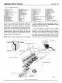
ROCKER ARM
ROCKER
SHAFT
RIGHT BANK
LUBRICATION
NO. 4 CAMSHAFT
BEARING
RIGHT MAIN OIL GALLERY
LEFT ROCKER SHAFT
OIL FILTER
Oil PUMP
OIL PRESSURE
RELIEF VALVE
Fig. 43 — Engine Oiling System
59x24
50—ENGINE
CHRYSLER SERVICE MANUAL
BOLT\
RETAINER
SPACER
WASHER
ROCKER
BRACKET
GEARAND SHAFT
SPROCKET
CHAIN
CAMSHAFT
BOLT
OIL SEAL
(SERVICED IN PACKAGE)
BEARING
CRANKSHAFT
SPROCKET
OIL SLINGER
RETAINER SCREW
CAP
SCREW
_~-—~—SCREW
SCREW
CAP {SERVICED IN ROD)
NUT
CAP
Fig. 44 — Engine Internal Parts
59x53
CHRYSLER SERVICE MANUAL
ENGINE—51
3662 for disassembly using the transmission mounting bolts.
INSTALLING THE ENGINE ASSEMBLY (In Car)
Remove the engine from repair stand and install
transmission. Install the engine lifting fixture Tool
C-3466 and attach the chain hoist to fixture eyebolt.
Raise the engine. Lower the engine carefully into
the car until front and rear of engine are approximately positioned. Place a rollaway jack under the
transmission to support the weight of rear of the
engine. Install the engine rear support crossmember.
Position the engine and install the nuts at front engine mounts. Position and install rear engine support bolts and remove the jack, hoist and engine
lifting fixture.
Install the carburetor, fuel lines, wiring and linkage. Install the radiator, fan shroud and radiator
hoses. Connect exhaust pipes, using new gaskets.
Install the hood, being sure to align hood by the
scribe marks placed on the inside of hood at disassembly. Connect the propeller shaft at the transmission. Connect linkage and wires. Be sure all drain
cocks are closed, and fill cooling system. Fill the
engine crankcase and transmission. Refer to the lubrication Section for quantities and lubricants to use.
Check the entire system for leaks and correct as
necessary.
NOTE: Whenever an engine has been rebuilt and a
new camshaft and/or new tappets have been installed,
add one quart of factory recommended oil additive
to engine oil to aid break-in (MoPar Engine Oil Additive, Part No. 1643234). The oil mixture should
be left in engine for a minimum of 500 miles, and
drained at the next normal oil change.
INTAKE VALVES
&&^5>-
58x137
Fig. 46 — Tightening Sequence
Start the engine and run until normal operating"
temperature is reached. Check the timing and adjust
carburetor as necessary. Road test the car.
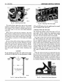
CYLINDER HEADS
The chrome alloy cast iron cylinder heads as shown
in Figure 45 are held in place by 17 bolts. The spark
plugs enter the cylinder head horizontally and are
located at the wide edge of the combustion, chambers.
a. Removal
Drain the cooling system. Remove generator, carburetor air cleaner and fuel line. Disconnect the accelerator linkage. Remove the vacuum control tube at
carburetor and distributor. Disconnect the distributor cap, coil wires and heater hose. Disconnect the
heat indicator sending unit wire. Remove spark
plugs located under the manifolds. Remove the intake manifold, ignition coil and carburetor as an
assembly. Remove the tappet chamber cover. Remove cylinder head covers and gaskets.
NOTE: On air conditioned cars, number eight cylinder exhaust valve must be open to allow clearance
between the right bank cylinder head cover and the
heater housing.
k:a
Remove the generator. Remove exhaust manifolds.
Remove the rocker arms and shaft assembly. Remove the push rods and place them in their respective slots in holder Tool C-3068. Remove the 17 head
bolts from each cylinder head and remove cylinder
heads. Place cylinder head in holding fixture Tool
C-3626.
EXHAUST
VALVES
b. Installation
58x136
Fig. 45 — Cylinder Heads
Clean the gasket surfaces of cylinder block and cylinder head. Check all surfaces with a straight edge
if there is any reason to suspect leakage. Coat the
CHRYSLER SERVICE MANUAL
52—ENGINE
LOCATING ARROW
EXHAUST MANIFOLD - RiGHT
ROCKER ARMS-RIGHT
, TOOL
mam*
; i
• . ROCKER ARMS-RIGHT
V> X 1 M
LOCATIMOARROW
58xl?9
Fig. 47 — Checking Cylinder Head Bolt Torque
Fig. 49 — Rocker Arms Installed
new gaskets with a suitable sealer, MoPar Part
Number 1122893. Install the gaskets and cylinder
heads. Install cylinder head bolts. Starting at top
center, tighten all cylinder head bolts to 70 footpounds torque in sequence, as shown in Figure 46,
and using Tool C-3666 to check torque, as shown in
Figure 47.
Repeat the procedure, retightening all head bolts
to 70 foot-pounds torque. Inspect push rods and replace worn or bent rods. Install push rods with the
small ends in tappets maintaining alignment using
rod, as shown in Figure 48.
Install the rocker arm and shaft assembly starting
each push rod into its respective rocker arm socket.
NOTE: Use extreme care in tightening bolts 30 footpounds torque, so the tappets have time to bleed
down to their operating length. Bulged tappet bodies,
CYLINDER HEAD
ASSEMBLIES
INTAKE PUSH RODS
bent push rods, and permanently noisy operation
may result if the tappets are forced down too rapidly.
Place the new cylinder head cover gaskets in position and install cylinder head covers. Tighten the
bolts to 40 inch-pounds torque. Install exhaust manifolds and tighten the bolts to 30 foot-pounds torque.
Adjust spark plugs to .035 inch gap and install the
plugs, and tighten to 30 foot-pounds torque with
Tool C-3054. Install the tappet chamber cover and
tighten end bolts to 8 foot-pounds torque (Fig. 49).
Install intake manifold, carburetor and ignition
coil as an assembly and tighten manifold bolts to 40
food-pounds torque. Install the distributor cap. Connect the coil wire, heat indicator sending unit wire,
accelerator linkage, spark plug cables and insulators.
Install the vacuum tube from carburetor to distributor. Install generator and tighten generator bracket
bolts to 50 foot-pounds torque, and generator mounting nut to 20 foot-pounds torque. Install the fuel line
and carburetor air cleaner. Fill the cooling system.
Adjust belt tensions as outlined in "Accessory Belt
Drives" in this supplement.
-BRACKETS-
OIL FEED GROOVE
THIS SIDE
OIL FEED
GROOVE
THIS SIDE
SPACERS-
INSTALLING ROD
58x140
EXHAUST PUSH RODS
Fig. 48 — Push Rods Installed
"58x138
Fig. 50 — Rocker Arms & Shaft Assembly
CHRYSLER SERVICE MANUAL
ENGINE—53
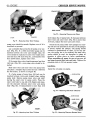
ROCKER ARMS AND SHAFT ASSEMBLY
The rocker arms are of stamped steel and are arranged on one rocker arm shaft, per cylinder head.
The push rod angularity tends to force the pairs of
rocker arms toward each other where oilite spacers
carry the side thrust at each rocker arm. Five brackets attach each rocker shaft to the cylinder head.
"OOU
a. Removal
Remove cylinder head cover and gasket. Remove the
bolts that attach rocker arm support brackets to
cylinder head and remove the rocker arms, brackets
and shaft as an assembly.
If the rocker arm assemblies have been disassembled for cleaning, inspection, or replacement, refer
to Figure 49 and 50 for proper reassembly.
b. Installation
NOTE: The right and left rocker arms must be installed on rocker shaft, as shown in Figure 49. The
stamped arrow on rocker shaft must be on top and
the arrow must point toward the push rod socket of
the rocker arm. This is necessary to provide proper
lubrication to the rocker assemblies. The two wide
brackets must be installed with the oil feed grooves
facing the push rod side of rocker arm, as shown in
Figures 49 and 50.
Install the rocker arms, brackets, and shaft assembly.
NOTE: Use extreme care in tightening the bolts so
Fig. 52 — Using Sleeve Tool in Checking Wear
that tappets have time to bleed down to their operating length. Bulged tappet bodies, bent push rods and
permanent noisy operation may result if the tappets
are forced down too rapidly.
Tighten the bolts to 30 foot-pounds torque.
VALVES AND VALVE SPRINGS
Valves are arranged in-line in the cylinder heads and
inclined 30° outward from vertical. Intake and exhaust valves operate in guides that are integral with
the heads.
a. Removal
With the cylinder head removed, compress valve
springs using Tool. C-3422, as shown in Figure 51.
Remove the valve retaining locks, valve spring
retainers, valve stem cup seals and valve springs. Remove the burrs from valve stem lock grooves to prevent damage to the valve guide when valves are removed.
TOOL
CYLINDER HEAD
ASSEMBLY
b. Valve Inspection
Clean the valves thoroughly, and discard burned,
warped and cracked valves. Measure valve stems for
wear. Intake valve stem diameter should measure
.372 to .373 inch and exhaust valve stem diameter
should measure .371 to .372 inch. If the wear exceeds
.002 inch, replace the valve. Remove carbon and varnish deposits from the inside of valve guides with
cleaner, Tool C-756.
REPAIR" STAND
(TOOL)
58x141
Fig. 51 — Compressing Valve Spring
58x142
Measure the valve stem guide clearance as follows : Install sleeve Tool C-3026 over the valve stem,
as shown in Figure 52, and install valve.
CHRYSLER SERVICE MANUAL
54—ENGINE
VALVE
TOOL
VALVE
^MINIMUM MEASUREMENT
58x143
MAXIMUM MEASUREMENT
Fig. 53 — Measuring Guide Wear
58x144A
Fig. 55 — Measuring Valve Stem Length
The special sleeve places the valve at the correct
height for checking with a dial indicator. Attach the
dial indicator Tool C-3339 to cylinder head and set
it at right angle of the valve stem being measured
(Fig. 53).
Move valve to and from the indicator. The total
dial indicator reading should not exceed .010 inch on
intake valves, and .014 inch on exhaust valves. Ream
the guides for valves with oversize stems if dial indicator reading is excessive or if the stems are scuffed
or scored.
Service valves with oversize stems are available in
.005, .015 and .030 inch oversizes. Reamers to accommodate the oversize valve stem are as follows: Reamer Tool C-3433 (.379 to .380 inch) Reamer Tool C3427 (.404 to .405 inch). Slowly turn reamer by hand
and clean guide thoroughly before installing new
valve.
CAUTION
Do not attempt to ream the valve guides from standard directly to .030 inch. Use step procedure of .005,
MARGIN
.015 and .030 inch so the valve guides may be reamed
true in relation to the valve seat.
c. Referring valves and valve seats
The intake and exhaust valve faces have a 45° degree angle. Always inspect the remaining margin
after the valves are refaced (Fig. 54). Valves with
less than 3/64 inch margin should be discarded.
The angle of both valve and seat should be identical. When refacing the valve seats with Tool MTH80, it is important that the correct size valve guide
pilot be used for reseating stones. A true and complete surface must be obtained. Measure the concentricity of valve seat using a dial indicator. The total
runout should not exceed .002 inch (total indicator
reading). When the seat is properly positioned, the
width of intake seats should be 1/16 to 3/32 inch.
The width of exhaust seats should be 3/64 to 1/16
inch.
When the valves and seats are reground, the position of the valve in the cylinder head is changed,
shortening the operating length of hydraulic tappet.
This means that the plunger is operating closer to
its bottomed position, and less clearance is available
for thermal expansion of valve mechanism during
FACE
VAtve
SPRiNG
STEM-
VALVE SPRING RETAINER
LOCK GROOVES
54x33CC
Fig. 54 — Intake and Exhaust Valve
Fig. 56 — Checking Valve Spring Squareness
ENGINE—55
CHRYSLER SERVICE MANUAL
high speed driving. The design of the valve mechanism includes a safety factor to allow for a limited
amount of wear, and the refacing of valves and
seats.
To insure that the limits have not been exceeded,
the dimension from valve spring seat in head to
valve tip should be measured with Gauge, Tool C3648, as shown in Figure 55.
The end of the cylindrical gauge and the bottom
of slotted area represent the maximum and minimum allowable extension of valve stem tip beyond
the spring seat. If the tip exceeds maximum, grind
the stem tip to within gauge limits. Clean tappets if
tip grinding is required.
d. Testing Valve Springs
Whenever the valves have been removed for inspection, reconditioning or replacement, the valve
springs should be tested. To test a spring, first determine the length at which the spring is to be tested.
As an example, the compressed length of the spring
to be tested is 1-15/32 inches. Turn the table of Tool
C-647 until surface is in line with the 1-15/32 inch
mark on the threaded stud and the zero mark to the
front. Place spring over stud on table and lift the
compressing lever to set the tone device. Pull on
torque wrench until a ping is heard. Take the reading on torque wrench at this instant. Multiply this
reading by two. This will give the spring load at the
test length. Fractional measurements are indicated
on the table for finer adjustments. The valve springs
should test 183 to 202 lbs. when compressed to 115/32 inch. Discard springs that do not meet these
specifications.
Inspect each valve spring for squareness with a
RETAINER
Fig. 58 — Installing Valves and Cup Seals
steel square and surface plate, as shown in Figure
56.
If the spring is more than 1/16 inch out of square,
install a new spring.
e. Installation
Coat the valve stems with lubricating oil and insert
them in position in cylinder head. Install the cup
seals on intake and exhaust valve stems and over
valve guides, as shown in Figure 57 and 58 and install valve springs and retainers.
Compress the valve springs with Tool C-3422. Install locks and release tool.
NOTE: If the valves and/or seats are reground,
measure the installed height of springs. Make sure
measurement is taken from the bottom of the spring
seat in cylinder head to the bottom surface of spring
retainer. (If spacers are installed, measure from the
top of spacer.) If height is greater than 1-57/64
inches, install a 1/16 inch spacer in head counterbore to bring spring height back to normal 1-53/64
to 1-57/64 inch.
HYDRAULIC TAPPETS
a. Preliminary to Checking Hydraulic Tappets
EXHAUST
VALVE
SPRING
INTAKE VALVE
59x51
Fig. 57 — Valve Assembly
Before disassembling any part of engine to correct
tappet noise, read the oil pressure at gauge and
check the oil level in the oil pan. The pressure should
be between 45 and 70 pounds at 2000 rpm. The oil
level in the pan should never be above "full" mark
on dip stick, or below "add oil" mark. Either of these
two conditions could be responsible for noisy tappets.
Oil Level Too High — If oil level is above "full"
mark on dip-stick, it is possible for the connecting
CHRYSLER SERVICE MANUAL
56—ENGINE
rods to dip into oil while the engine is running and
create foam. Foam in the oil pan would be fed to
the hydraulic tappets by the oil pump causing them
to go flat and allowing the valves to seat noisily.
Oil Level Too Low — Low oil level may allow the oil
pump to take in air which, when fed to tappets,
causes them to lose length and allows the valves to
seat noisily. Any leaks on intake side of the pump
through which air can be drawn will create the same
tappet action. When tappet noise is due to aeration,
it may be intermittent or constant, and usually more
than one tappet will be noisy. When oil level and
leaks have been corrected, the engine should be operated at fast idle for sufficient time to allow all of
air inside of tappets to be bled out.
f
7*-PLUNGER RETAINING SPRING CLIP
v—' y%+
-PLUNGER CAP
TAPPET PLUNGER
FLAT VALVE
VALVE SPRINGVALVE RETAINER*
PLUNGER SPRING-
TAPPET BODY
52x389B
Fig. 60 — Hydraulic Tappet Assembly
b. Tappet Noises
To determine the source of tappet noise, operate the
engine at idle with the cylinder head covers removed. Feel each valve spring or rocker arm to detect the noisy tappet. The noisy tappet will cause
the affected spring and/or rocker arm to vibrate or
feel rough in operation.
NOTE: Worn valve guides or cocked springs are
sometimes mistaken for noisy tappets. If such is the
case, noise may be dampened by applying side thrust
on valve spring. Inspect rocker arm push rod sockets
and push rod ends for wear. If noise is not appreciably reduced, it can be assumed the noise is in the
tappet.
Valve tappet noise ranges from a light noise to a
heavy click. A light noise is usually caused by excesCYLINDER HEAD
ASSEMBLY
HYDRAULIC TAPPET
sive leakdown around the unit plunger, or by the
plunger partially sticking in the tappet body cylinder. A heavy click is caused either by a tappet check
valve not seating, or by foreign particles becoming
wedged between the plunger and tappet body, causing plunger to stick in the down position. This heavy
click will be accompanied by excessive clearance between valve stem and rocker arm as valve closes.
In either case, the tappet assembly should be removed for inspection and cleaning.
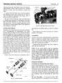
c. Removal of Tappets
Tappets can be removed without removing the intake manifold by following this recommended procedure: remove the cylinder head covers. Remove
rocker arms and shaft assembly. Remove the push
rods and place them in their respective holes in Tool
C-3068. Slide puller Tool C-3661 through push rod
opening in cylinder head and seat tool firmly in the
head of tappet. Pull tappet out of bore with a twisting motion, as shown in Figure 59.
If all tappets are to be removed, remove the hydraulic tappets and place them in their respective
holes in tappet and push rod holder, Tool C-3068.
This will insure installation of the tappets in their
original locations.
NOTE: A diamond shaped marking stamped on the
engine numbering pad indicates that all tappet bodies
are .008 inch oversize, see Figure 84.
Fig. 59 — Removing Tappet
CAUTION
Do not disassemble a tappet on a dirty work bench.
The plunger and tappet bodies are not interchangeable. The plunger and valve must always be fitted to
the original body. It is advisable to work on one tap-
CHRYSLER SERVICE MANUAL
ENGINE—57
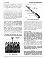
3160, in the groove of tappet body (Fig. 61).
Engage jaw of pliers with top of the tappet plunger. Check leakdown by compressing pliers. If plunger collapses almost instantly as pressure is applied, disassemble tappet, clean and test again. If the
tappet still does not operate satisfactorily after
cleaning, install a new tappet assembly.
h. Installation
Lubricate the tappets. Install tappets and push rods
in their original positions. Install the rocker arm
and shaft assembly. Start and operate the engine.
Warm up to normal operating temperature.
51x971D
Fig. 61 — Testing Tappet
pet at a time to avoid mixing of parts. Mixed parts
are not compatable.
d. Disassembly (Fig. 60)
Pry out plunger retainer spring clip. Clean the varnish deposits from the inside of tappet body above
the plunger cap. Invert the tappet body and remove
plunger cap, plunger, flat check valve, check valve
spring, check valve retainer and plunger spring.
Separate the plunger, check valve retainer and check
valve spring. Place all parts in their respective place
in the tappet holder Tool C-3068.
e. Cleaning and Assembly
Clean all tappet parts in a solvent that will remove
all varnish and carbon. Replace the tappets that are
unfit for further service with new assemblies. Assemble the tappets, as shown in Figure 56.
f. Inspection
If the tappet or bore in cylinder block is scored,
scuffed, or shows signs of sticking, ream the bore to
next oversize, using Tool C-3028. If plunger shows
signs of scoring or wear and valve is pitted, or if
the valve seat on end of plunger indicates any condition that would prevent valve from seating, install
a new tappet assembly.
g. Testing
Fill a pan with clean kerosene. Remove cap from
plunger and completely submerge the tappet in an
upright position.
Allow tappet to fill with kerosene, remove tappet,
and replace the cap. Hold the tappet in an upright
position and insert the lower jaw of pliers, Tool C-
NOTE: To prevent damage to valve mechanism, the
engine must not be run above fast idle until all of
hydraulic tappets have filled with oil and have become quiet.
CHECKING VALVE TIMING
Turn crankshaft until the No. 1 exhaust valve is
full open and the No. 1 piston is on TDC.
Insert a *4 inch spacer between the rocker arm
pad and the stern tip of the No. 1 intake valve (second valve on the left bank). Install a dial indicator
so that the plunger contacts the valve spring retainer as nearly perpendicular as possible. Allow the
spring load to bleed the tappet down giving in effect
a solid tappet. Zero the indicator.
Turn the crankshaft clockwise (normal running
direction) until intake valve has lifted .013 inch.
The timing on the timing indicator, located on the
chain case cover, should read from 10° BTDC to
2° ATDC. If the reading is not within the specified
limits: Check the sprocket index marks, inspect the
timing chain for wear, and check the accuracy of
the DC mark on the timing indicator. Turn crankshaft counter-clockwise until the valve is closed and
remove the spacer.
- C H A I N CASE COVER
- - TIMING INDICATOR
- -CYLINDER BLOCK
- TIMING MARK
VIBRATION DAMPER
^
58x149A
Fig. 62 — Removing Vibration Damper Assembly
58—ENGINE
CHRYSLER SERVICE MANUAL
CAUTION
TORQUE WRENCH
Do not turn crankshaft any further clockwise as the
valve spring might bottom and result in serious
damage.
TIMING SPROCKETS AND CHAIN
The timing chain has 50 links of i/2 inch pitch and is
% inch wide. Chain stretch is reduced because of
fewer joints to wear.
a. Removal
Drain the cooling system. Remove the radiator and
water pump assembly. Remove the bolt holding vibration damper on crankshaft. Remove two of the
pulley bolts, install Tool C-3033, and pull the damper
assembly off the end of crankshaft, as shown in
Figure 62.
Remove the chain cover and gasket. Slide the
crankshaft oil slinger off end of crankshaft. Remove
the camshaft sprocket attaching bolt. Remove timing chain with crankshaft and camshaft sprockets.
b. Installation
Place both the camshaft sprocket and crankshaft
sprocket on the bench with timing marks on exact
imaginary center line through both camshaft and
crankshaft bores. Place the timing chain around
both sprockets. Turn the crankshaft and camshaft
to line up with the keyway location in crankshaft
sprocket and the dowel holes in the camshaft sprocket. Lift the sprockets and chain, (keep sprockets
tight against the chain in position as described).
Slide both sprockets evenly over their respective
shafts. Use a straight edge to check alignment of
the timing marks (Fig. 63). Install the washer and
58x151
Fig. 64 — Measuring Chain Stretch
camshaft sprocket bolt and tighten to 35 foot-pounds
torque.
c. Checking Timing Chain for Stretch
Place a scale next to timing chain so that any movement of the chain may be measured. Place a torque
wrench and socket over the camshaft sprocket attaching bolt and apply torque in the direction of
crankshaft rotation to take up the slack; 30 footpounds torque (with cylinder heads installed) or
15 foot-pounds torque (cylinder heads removed).
Holding a scale with dimensional reading even with
edge of a chain link, apply torque in the reverse direction 30 foot-pounds (with cylinder heads installed) or 15 foot-pounds (cylinder heads removed), and note the amount of chain movement,
as shown in Figure 64. Install a new timing chain,
if its movement exceeds 11/64 inch.
NOTE: With a torque applied to camshaft sprocket
bolt, the crankshaft should not be permitted to move.
It may be necessary to block the crankshaft to prevent rotation.
CAMSHAFT SPROCKET
If chain is satisfactory, slide the crankshaft oil
slinger over shaft and up against the sprocket
(flange away from sprocket.)
TIMING CHAIN CASE COVER OIL SEAL
REPLACEMENT
a. Removal
CRANKSHAFT
SPROCKET
58x150
Fig. 63 — Alignment of Timing Marks
Position puller screw of Tool C-3506 through case
cover, the inside of case cover up. Position the puller
blocks directly opposite each other, and force the
angular lip between neoprene and flange of the seal
retainer. Place washer and nut on puller screw.
ENGINE—59
CHRYSLER SERVICE MANUAL
PULLER BLOCKS (TOOL)
LIP OF SEAL
RETAINER
CHAIN CASE COVER
INSTALLING
PLATE
(TOOL)
PULLER SCREW
(TOOL)
SEAL"
V '. "
'.V-*.- /
CHAIN CASE COVER
ASSEMBLY
!
'• ' ^ . ? ^ ^ T >--•
58x152
Fig. 65 — Puller Blocks Expanded to Pulling Position
Tighten the nut as tight as possible by hand, forcing
blocks into gap to a point of distorting the seal retainer lip (Fig. 65). This is important (puller is
only positioned at this point). Place sleeve over the
retainer and place removing and installing plate
into sleeve. Place the flat washer and nut on puller
screw. Hold the center screw and tighten lock nut
to remove seal (Fig. 66).
b. Installation of Oil Seal
Insert puller screw through removing and installing
plate so that the thin shoulder will be facing up.
Insert puller screw with plate through the seal
opening (inside of chain case cover facing up). Place
the seal in cover opening, with neoprene down. Place
the seal installing plate into the new seal, with protective recess toward lip of seal retainer (Fig. 67).
Install the flat washer and nut on puller screw, hold
screw and tighten the nut (Fig. 68).
The seal is properly installed when neoprene is
tight against the face of cover. Try to insert a .0015
inch feeler gauge between neoprene and cover (Fig.
69). If the seal is installed properly, the feeler gauge
cannot be inserted.
58x154
Fig. 67 — Positioning Installer Plate on New Seal
NOTE: It is normal to find particles of neoprene
collected between the seal retainer and crankshaft
oil slinger after the seal has been in operation.
c. Installing Chain Case Cover
Be sure the mating surfaces of chain case cover and
cylinder block are clean and free from burrs. Using
PULLER SCREW (TOOL)
INSTALLING PLATE
(TOOL)
SEAL'7
RETAINER
CHAIN CASE COVER
-:
58x155
Fig. 68 — Installing New Seal
PULLER SCRFW (TOOL)
REMOVING AND
INSTALLING PLATE
(TOOL)
•SLEEVE (TOOL) ^
FEELER GAUGE?
\
"••*'
SEAL
CHAIN CASE
COVER
CHAIN CASE
58x153
Fig. 66 — Removing Oil Seal
Fig. 69 — Checking Seal for Proper Seating
60—ENGINE
CHRYSLER SERVICE MANUAL
A
CHAIN CASE COVER
TIMING INDICATOR
CYLINDER BLOCK
TIMING MARK
VIBRATION DAMPER
/
TOOL
58x157A
58x159
Fig. 70 — Installing Vibration Damper Assembly
a new gasket slide the chain case cover over the locating dowels and tighten bolts to 15 foot-pounds
torque.
d. Installing Vibration Damper
Place the damper hub key in slot in crankshaft, and
slide hub on crankshaft. Place the installing tool,
part of Puller set Tool C-3033 in position and press
damper hub on the crankshaft (Fig. 70). Slide the
pulley over the shaft and attach with bolts and lockwashers. Tighten the bolts to 15 foot-pounds torque.
Install damper hub retainer washer and bolts.
Tighten to 135 foot-pounds torque.
Fig. 72 — Removing Distributor Drive Shaft Bushing
tor drive shaft. Remove the fuel pump to allow the
push rod to drop away from the cam eccentric. Remove the camshaft being careful not to damage the
cam bearings with the cam lobes.
DISTRIBUTOR DRIVE SHAFT BUSHINGS
a. Removal
Insert Tool C-3052 into old bushing and thread down
until a tight fit is obtained (Fig. 72). Hold the puller screw and tighten puller nut until bushing is removed.
CAMSHAFT
b. Installation
The camshaft has an integral oil pump and distributor drive gear and fuel pump eccentric, as shown in
Figure 71.
Rearward camshaft thrust is taken by the rear
face of the cast iron camshaft sprocket hub, bearing
directly on the front of the cylinder block, eliminating the need for a thrust plate. The helical oil pump
and distributor drive gear and the camshaft lobe
taper both tend to produce only a rearward thrust.
Slide new bushing over burnishing end of Tool C3053 and insert the tool and bushing into bore, as
shown in Figure 73.
Removal
Drive bushing and tool into position, using a soft
hammer. As the burnisher is pulled through bushing
by tightening puller nut, the bushing is expanded
tight in block and burnished to correct size, as shown
in Figure 74. DO NOT REAM THIS BUSHING.
BUSHING
With the tappets and timing sprockets removed, remove distributor and lift out oil pump and distribuBOIT
WASHER
CAMSHAFT SPROCKET
TOOL
CAMSHAFT
'•**?* A*v
-DISTRIBUTOR DRIVE GEAR
(CAMSHAFT;
FUEL PUMP ECCENTRIC (CAMSHAFT)
LOCATING DOWEL
Fig. 71 — Camshaft and Sprocket Assembly
58x160
Fig. 73 — Installing Distributor Drive Shaft Bushing
CHRYSLER SERVICE MANUAL
ENGINE—61
DISTRIBUTOR A N D OIL
PUMP DRIVE
GEAR
^58x161
Fig. 74 — Burnishing Distributor Drive Shaft Bushing
c. Camshaft Installation
Lubricate the camshaft lobes and camshaft bearing
journals and insert the camshaft to within 2 inches
of its final position in the cylinder block. Modify
Tool C-3509 by grinding off the index lug holding
upper arm on the tool and rotate arm 180°. Install
Tool C-3509 in place of distributor drive gear and
shaft, as shown in Figure 75. Hold the tool in position with distributor lock plate screw. This tool will
restrict the camshaft from being pushed in too far
and prevent knocking out the welch plug in the rear
of the cylinder block. The tool should remain installed until the camshaft and crankshaft sprockets
and timing chain have been installed.
NOTE: Whenever an engine has been rebuilt and a
new camshaft and/or new tappets have been installed, one quart of factory recommended oil additive should be added to the engine oil to aid in breakin. The oil mixture should be left in the engine for a
minimum of 500 miles. Drain the oil mixture at the
next normal oil change.
TOOL
CENTER LINE OF CRANKSHAFT
Fig. 76 — Distributor Drive Gear Installation
NOTE: Whenever the camshaft is replaced, all of
the tappet faces must be inspected for crown with a
straight edge. If any negative crown (dish) is observed, the tappet must be replaced.
d. Distributor (Basic) Timing
Before installing the distributor and oil pump drive
shaft, time engine as follows: Rotate the crankshaft
until No. 1 cylinder is at top dead center on firing
stroke. When in this position, the straight line on
the vibration damper should be under (DC) on the
timing indicator. Coat shaft and drive gear with engine oil. Install the shaft so that after the gear spirals into place, it will index with oil pump shaft, so
that the slot in top of drive gear will be parallel with
center line of crankshaft as shown in Figure 76.
e. Installation of Distributor
Hold distributor over the mounting pad on cylinder
block with the vacuum chamber pointing toward the
center of engine. Turn the rotor until it points forward and to the approximate location of the No. 1
tower terminal in the distributor cap. Place distributor gasket in position. Lower distributor and en-
ARM (TOOL)
CRANKSHAFT MAIN BEARING OIL HOLE
DISTRIBUTOR DRIVE GEAR (CAMSHAFT)
-C
58x162
BEARING OIL HOLE]
58x164
Fig. 75 — Camshaft Holding Tool
Fig. 77 — Removing Camshaft Bearing
62—ENGINE
CHRYSLER SERVICE MANUAL
gage shaft in slot of distributor drive shaft gear.
Turn distributor clockwise until the breaker contacts
are just separating and install hold down clamp.
REMOVAL AND INSTALLATION OF CAMSHAFT
BEARINGS (Engine Removed from Car)
a. Removal
With the engine completely disassembled, drive out
the rear cam bearing welch plug. Install proper size
adapters and horse shoe washers (part of Tool C3132A) at back of each bearing shell to be removed
and drive out the bearing shells. \
b. Installation
Install the new camshaft bearings with Tool C-3132A by sliding the new camshaft (bearing shell over
the proper adapter. Position bearing in the tool. Install horse shoe lock and by reversing removal procedure, carefully drive bearing sliell into place, as
shown in Figure 77. Install remaining shells in like
manner.
NOTE: Install the No. 1 camshaft bearing 1/32" inward from front face of the cylinder block.
The oil holes in camshaft bearings and cylinder
block must be in exact alignment to insure proper
lubrication (Fig. 77).
Camshaft bearing index can be checked after installation by inserting a pencil flashlight in the bearing shell. The camshaft bearing oil hole should be
perfectly aligned with the drilled oil passage from
the main bearing. Another oil hole in the camshaft
bearings should be visible by looking down on the
left bank oil hole above and between No. 6 and No.
8 cylinders to No. 4 camshaft bearing and on the
right bank above and between NoL 5 and 7 cylinders
to No. 4 camshaft bearings. If the; camshaft bearing
shell oil holes are not in exact Alignment, remove
and reinstall them correctly. Use| Tool C-897 to install a new welch plug at the reajr of camshaft. Be
sure this plug does not leak.
CYLINDER BLOCK
plugs are installed, coat the edges of plug and core
hole with a suitable sealer and drive plugs in place
with driver, Tool C-897. Examine block for cracks
or fractures. Remove the top ridge of cylinder bores
with a reliable ridge rearmer before removing the
pistons from cylinder block. Be sure to keep the tops
of pistons covered during this operation.
NOTE: Pistons and connecting rods must be removed
from the top of cylinder block. When removing piston and connecting rod assemblies from the engine,
rotate crankshaft so each connecting rod is centered
in the cylinder bore.
Remove connecting rod cap. Install Tool C-3221
on one connecting rod bolt and protector over the
other bolt and push each piston and rod assembly
out of the cylinder bore. After removal, install bearing cap on mating rod.
a. Checking Cylinder Bores
The cylinder bores should be checked for out-ofround and taper with Tool CM-119. If the cylinder
bores show more than .005 inch out-of-round or a
taper of more than .010 inch the cylinder block
should be rebored and honed, and new pistons and
rings fitted.
b. Honing Cylinder Bores
To remove light scoring, scuffing, or scratches from
the cylinder walls, use Tool C-823. Usually a few
strokes will clean up a bore and maintain the required
limits. The cylinder walls should be deglazed, using
cylinder surfacing hone Tool C-3501 equipped with
280 grit stones, prior to installation of the new rings
or to smooth down the cylinder walls after rough
honing. A satisfactory finish can be obtained by
PISTON RING
FEELER GAGE x
RING GROOVE
|
The cylinder block is of the deep lj>lock design which
eliminates the need for a torque converter housing
adapter plate. Its sides extend three inches below
the crankshaft centerline.
Cleaning and Inspection
j
Clean cylinder block thoroughly ^nd check all core
hole plugs for evidence of leaking. If new core hole
58x165
Fig. 78 — Measuring Piston Ring Clearance
ENGINE—63
CHRYSLER SERVICE MANUAL
giving each cylinder wall 20 strokes in 20 seconds
with the hone so that a cross hatch pattern will be
obtained.
NUT CTOOl)
ANVIL (TOOL)
PISTON
After honing, it is necessary that the block be
cleaned again to remove all traces of abrasives, and
to prevent excessive wear of engine parts. The hone
may be safely used for removal of metal up to .005
inch and as high as .010 to .015 inch by an experienced operator.
CAUTION
Be sure all abrasives are removed from engine parts
after honing. It is recommended that a solution of
soap and water be used with a brush and then thoroughly dried. If this is impossible, use SAE 10 engine oil and CLEAN cloth. When the bore can be
wiped with a clean white cloth and be withdrawn
clean, the bore is clean.
c. Cylinder Walls
Cylinder walls which are badly scored, scuffed,
scratched, or worn beyond specified limits should
be rebored. Whatever type of boring equipment is
used, boring operation should be closely coordinated
with the fitting of pistons and rings in order that
specified clearance may be maintained.
d. Fitting Pistons
The piston and cylinder wall must be clean and dry.
The specified clearance between the piston and the
cylinder wall is .0005 to .0010 inch.
The piston diameter should be measured at the
top of skirt 90° to the piston pin axis. The cylinder
bores on used engines should be measured halfway
down the cylinder bore and transverse to the engine
crankshaft centerline.
NOTE: Pistons and cylinder bores should be measured at normal room temperature 70° F.
All service pistons include pins, and are available
in standard and the following oversizes, .005, .020
and .040 inch.
e. Fitting Rings
Measure the piston ring gap about two (2) inches
from bottom of cylinder bore in which it is to be
fitted. (An inverted piston can be used to push the
rings down to insure positioning rings squarely in
the cylinder wall before measuring.) Insert the feeler
stock in gap (Fig. 78).
The ring gap should be between .013 to .025 inch.
PILOT (TOOL)
MAIN
SCREW (TOOL)
GUIDE-SMALL
(TOOL)
PISTON PIN
CONNECTING ROD
58x195A
GUIDE-LARGE (TOOL)
Fig. 79 — Tool Arrangement of Removing Piston Pin
This measurement is the same for all rings. Measure the side clearance between piston ring and ring
land. The clearance should be .0015 to .003 inch
for the top compression ring, .001 to .0025 inch for
the intermediate ring, and .001 to .003 for the oil
control ring. Starting with the oil ring expander,
place expander ring in the lower ring groove and
install oil control ring. Install the compression rings
in middle and top grooves. Use ring installer, Tool
C-3629 for the MC-1 and MC-2 engine and Tool C3628 for the MC-3 and MY-1 engine.
NOTE: Be sure the mark "Top" on each compression ring is to the top of piston when the ring is installed.
REMOVAL OF PISTON PIN
Arrange Tool C-3624 parts for the removal of piston
pin, as shown in Figure 79. Install pilot on the main
screw. Install the screw through piston pin. Install
anvil over the threaded end of the main screw with
small end of anvil against the piston boss.
PRESS
MAIN SCREW
(TOOL)
PISTON
[58x166
Fig. 8 0 — Removing Piston Pin
CHRYSLER SERVICE MANUAL
64—ENGINE
-«*>^—-—- ANVIL (TOOL)
- SPRING
PILOT (TOOL)
PISTON
NUT
(TOOL)
PISTON PIN
MAIN SCREW
(TOOL)
TORQUE WRENCH
SOCKET
ANVfL
(TOOt)
GUIDE-SMALL
(TOOL)
58x196 A
MAIN SCREW
(TOOL)
GUIDE-LARGE (TOOL)
Fig. 81 — Tool Arrangement for Installing Piston Pin
NOTE: Be sure spring is removed from the anvil.
Install nut loosely on the main screw and place the
assembly on a press, as shown in Figure 80. Press
the piston pin out of connecting rod.
NOTE: When the pin falls free from connecting rod,
stop the press to prevent damage to bottom of the
anvil.
Remove the tool from the piston.
INSTALLATION OF PISTON PIN
Check the piston pin fit in the piston. It should be
a sliding fit in the piston at 70 °F. Piston pins are
supplied in standard sizes only. Lubricate piston pin
holes in the piston and connecting rod.
Arrange the tool parts for installation of piston
pin, as shown in Figure 81. Install the spring inside
the pilot and install the spring and pilot in the anvil.
Install the piston pin over main screw. Place piston,
with "front" up, over pilot so that the pilot extends
*
58x168
through the piston pin hole. Position connecting rod
over the pilot which extends through the piston hole.
NOTE: Assemble rods to pistons of the right cylinder
bank (2, 4, 6, and 8) with the indent on the piston
head opposite to the larger chamfer on the large bore
end of connecting rod. Assemble the rods to pistons
of the left cylinder bank ( 1 , 3, 5, and 7) with the indent on the piston head on the same side as the large
chamfer on the large bore end of connecting rod.
Install the main screw and piston pin in the piston, as shown in Figure 81.
Install the nut on puller screw to hold assembly
together. Place assembly on a press, as shown in
Figure 82. Press in the piston pin until piston pin
bottoms on the pilot properly positioning the pin in
the connecting rod. Remove the tool and arrange tool
parts and piston assembly in the same manner, as
shown in Figure 79.
- PRESS
:
i 'L*- - lV>A:N SCREW
*• f
TOOL)
PISTON PIN «PISTON
•• - ANVIL ITOOU
"58x16?
Fig. 82 — Installing Piston Pin
A
Fig. 83 — Testing Fit on Piston Pin in Connecting Rod
58x169
Fig. 84 — External Identification
ENGINE—65
CHRYSLER SERVICE MANUAL
Place the assembly in a vise, as shown in Figure
83.
Attach the torque wrench to nut and check torque
up to 15 foot-pounds torque. If the connecting rod
moves downward on piston pin, reject this connecting rod and piston pin combination. Obtain a connecting rod with proper small end bore diameter
and repeat the installation, and checking procedure.
If connecting rod does not move under 15 footpounds torque, the piston pin and connecting rod
interference is satisfactory, the tool may be removed.
CONNECTING RODS
IMPORTANT
A Maltese Cross stamped on the engine numbering
pad (Fig. 84) indicates that engine is equipped with
a crankshaft which has one or more connecting rods
and main bearing journals finished .001 inch undersize. The position of the undersize journal or journals will be stamped on machined surface of No. 3
counterweight (Fig. 8 5 ) .
Connecting rod journals will be identified by the
letter "R" and main bearing journals by the letter
"M." Thus "M-l" indicates that No. 1 main bearing
is .001 inch undersize.
INSTALLING CONNECTING ROD BEARINGS
NOTE: Fit all rods on one bank until completed. Do
not alternate from one bank to another, because when
the rods are assembled to pistons correctly, they are
not interchangeable from one bank to another.
Each bearing cap has a small "V" groove across the
parting face. When installing the lower bearing shell,
make certain that the "V" groove in shell is in line
with "V" groove in cap. This allows lubrication of
the cylinder wall. The bearing shells should always
be installed so that small formed tang fits into ma-
( 4
LETTERS
chined grooves of rods. The side play should be from
.009 to .017 inch (two rods).
Limits of taper or out-of-round on any crankshaft
journals should be held to .001 inch. Bearings are
available in .001, .002, .003, .010 and .012 inch undersize.
NOTE: Install the bearings in pairs. Do not use a new
bearing half with an old bearing half. Do not file the
rods or bearing caps.
CHECKING THE CONNECTING ROD BEARING
CLEARANCE (PLASTIGAGE METHOD)
Connecting rod bearing clearance measurements can
be made by the use of Plastigage with the engine in
the chassis. After removing the connecting rod cap,
wipe off the oil from the journal and inserts. Place
the Plastigage on bearing parallel with crankshaft.
Reinstall the cap and tighten attaching nuts alternately to specified torque.
Remove cap and measure the width of the compressed material with the graduated scale to determine the bearing clearance. Allowable clearance is
from .0005 to .0015 inches. If taper of the compressed material is evident, measure with the graduated scale. If the taper appears to exceed .005 inch,
the journal should be checked with micrometers.
INSTALLING PISTON AND CONNECTING ROD
ASSEMBLY IN CYLINDER BLOCK
Before installing the pistons, rods, and rod assemblies in bore, be sure that compression ring gaps are
diametrically opposite one another and not in line
with oil ring gap. The oil ring expander gap should
be toward the outside of the "V" of the engine. The
oil ring gap should be turned toward the inside of
the "V" of engine. Immerse the piston head and
rings in clean engine oil, slide the ring compressor,
Tool C-385, over the piston and tighten with the
special wrench (part of Tool C-385). Be sure the
position of rings does not change during this operation. Screw the connecting rod bolt protector (part
of Tool C-3221) on one rod bolt, and insert the rod
and piston into cylinder bore.
NOTE: Rotate the crankshaft so that connecting rod
journal is on center of the cylinder bore.
55x162
Fig. 85 — Internal Identification
Attach the puller part of Tool C-3221 on the other
bolt, and guide the rod over the crankshaft journal,
as shown in Figure 86.
Tap piston down in the cylinder bore, using the
66—ENGINE
CHRYSLER SERVICE MANUAL
upper main bearing halves of 1, 2, 4 and 5 numbers
are interchangeable. Upper and lower bearing halves
are not interchangeable because the upper bearing
is grooved and the lower is not.
CRANKSHAFT JOURNAL
Fig. 86 — Removing and Installing Connecting Rod
handle of a hammer. At the same time, guide connecting rod into position on crankshaft journal. The
notch or groove on the top of the piston must be
pointing toward front of the engine and the larger
chamfer of the connecting rod bore must be installed
toward crankshaft journal fillet. Install the rod caps,
tighten nuts to 45 foot-pounds torque.
CRANKSHAFT MAIN JOURNALS
The crankshaft journals should be checked for excessive wear, taper and scoring. Journal grinding
should not exceed .012 inch under the standard journal diameter. DO NOT grind the thrust faces of No.
3 main bearing. DO NOT nick the crankpin or main
bearing fillets. After regrinding, remove the rough
edges from crankshaft oil holes and clean out all oil
passages.
CRANKSHAFT MAIN BEARINGS
The lower main bearing halves of 1, 2, 4 and 5 numbers are interchangeable, as shown in Figure 87. The
The upper and lower No. 3 bearing halves are
flanged to carry the crankshaft thrust loads and are
not interchangeable with any other bearing halves in
the engine.
NOTE: Bearings that are not badly worn or pitted
must be reinstalled in the same position.
The bearing caps are not interchangeable and
should be marked at removal to insure correct assembly. Bearing shells are available in standard and
the following undersizes: .001, .002, .003, .010 and
.012 inch. Never install an undersize bearing shell
that will reduce the clearance below specifications.
REMOVAL AND INSTALLATION OF THE
MAIN BEARINGS
a. Removal
Remove the oil pan and mark bearing caps before
removal. Remove bearing caps one at a time. Remove
upper half of bearing by inserting Tool C-3059 (Fig.
88) into the oil hole of crankshaft. Slowly rotate
crankshaft clockwise, forcing out upper half of bearing shell.
Checking the Main Bearing Clearance
Plastigage Method. Use the same technique as described in "Checking the Connecting Rod Bearing
Clearance."
CAUTION
If bearings are measured with the engine in the chasBEARING
UPPER
>THRUST BEARING
LOWER
m m m.
Fig. 87 — Main Bearing Identification
INSTALLING • [ 5 1 x 9 3 A
x!72
Fig. 88 — Removing and Installing Main
Bearing Upper Shell
ENGINE—67
CHRYSLER SERVICE MANUAL
sis, the crankshaft must be supported in order to
take up clearance between the upper bearing insert
and the crankshaft journal. This can be done by
snugging bearing caps of the adjacent bearings with
.005 to .015 inch cardboard between lower bearing
shell and journal. Use extreme caution when this is
done to avoid unnecessary strain on the crankshaft
or bearings, or false reading may be obtained. Do not
rotate crankshaft while plastigage is installed. Be sure
to remove cardboard before reinstalling oil pan.
It is permissible to use one .001 inch undersize
bearing shell with one standard bearing shell or one
.002 inch bearing shell. Always use the smaller diameter bearing half as the upper. Never use a new
bearing with a used bearing and never use an upper
bearing half more than .001 inch smaller than the
lower bearing half.
b. Installation of the Upper Main Bearing
NOTE: When installing a new upper bearing shell,
slightly chamfer the sharp edge from the plain side.
Start bearing in place, and insert Tool C-3059 into
the oil hole of crankshaft (Fig. 88). Slowly rotate
the crankshaft counter-clockwise sliding the bearing
into position. After all bearings have been fitted,
tighten all caps to 85 foot-pounds torque. The crankshaft end play should be .002 to .007 inch.
OIL PAN (ALL MODELS)
a. Removal
Drain the oil and remove dipstick. Disconnect the
steering linkage from steering arm to allow the
steering linkage to be lowered. On single exhaust
system, the exhaust crossover pipe must be removed.
Be sure the rest of exhaust system is sufficiently
supported. It may be necessary to pull the brake line
located across the crossmember slightly forward to
allow enough clearance for pan removal. Remove oil
pan attaching bolts and lower the oil pan on MC-1
only. Disconnect throttle linkage at transmission and
at carburetor. Rotate the crankshaft until the centerline of the front counterweight is in the 10 o'clock
position. Remove the front engine mounting nuts
and raise the engine one inch. Remove the oil pan.
PLUG
GASKET
BOLTS A N D WASHERS
OIL FILTER
|CHN»
SPRING
RELIEF VALVE
PLUNGER
INNER ROTOR
AND SHAFT
BODY
DRIVE SHAFT
A N D GEAR
SEAL RING
GASKET
" O " RING
58x173
Fig. 89 — Oil Pump and Filter Assembly
attaching bolts. Tighten bolts to 15 foot-pounds
torque. Lower the engine and install front engine
mounting nuts and tighten to 85 foot-pounds torque.
Connect exhaust pipes (if removed) and steering,
throttle and carburetor linkage. Refer to Transmission Section in this manual. Refill the crankcase.
OIL PUMP
a. Removal
Remove oil pump attaching bolts and remove pump
and filter assembly from bottom side of the engine.
b. Disassembly
Remove the filter base and oil seal ring. Remove
pump rotor and shaft and lift out the outer pump
rotor. Remove oil pressure relief valve plug and lift
out spring and plunger (Fig. 89).
c. Inspection and Repair
Clean all parts thoroughly. The mating face of oil
IfRAIGHT
/
EDGE
b. Installation
NOTE: Check the alignment of the oil strainer. The
bottom of strainer must be on a horizontal plane
machined surface of the cylinder block. The foot of
strainer should touch bottom of the oil pan. Clean
pan thoroughly and install new gasket, oil pan and
FEELER
GAUGE
Fig. 90 — Checking Oil Pump Cover Flatness
CHRYSLER SERVICE MANUAL
68—ENGINE
STRAIGHT EDGE
FEEIER GAUGE
Fig. 93 — Measuring Clearance over Rotors
51x66A
DIAMETER
Fig. 91 —Measuring Outer Rotor Thickness
pump cover should be smooth. Replace cover if it is
scratched or grooved.
Lay a straight edge across the oil pump cover surface (Fig. 90). If a .0015 inch feeler gauge can be
inserted between the cover and straight edge, the
cover should be replaced. If outer rotor length measures less than .943 inch (Fig. 91), and diameter less
than 2.469 inches, replace outer rotor.
If the pump inner rotor length measures less than
.943 inch (Fig. 92) a new pump rotor should be installed.
Slide outer rotor and inner rotor into pump body
and place a straight edge across the face (between
the bolt holes), as shown in Figure 93.
If a feeler gauge of more than .004 inch can be
inserted between rotors and straight edge, replace
pump body. Remove pump inner rotor and shaft
leaving the outer rotor in pump cavity. Press the
outer rotor body to one side with fingers and measure the clearance between outer rotor and pump
body (Fig. 94). If measurement is more than .012
inch replace the oil pump body. If clearance between
inner rotor and outer rotor (Fig. 95) is more than
.010 inch, replace the inner and outer rotors.
Check the oil pump relief valve plunger for scoring and for free operation in its bore. If the plunger
is scored, replace the plunger. The spring should
conform to specifications on chart. If, for any reason, the spring has to be replaced, the same color
spring should be used. An exception is where oil
pressure is either above or below specifications.
When assembling oil pump, be sure to use new oil
seal rings between filter base and body. Tighten the
attaching bolts to 35 foot-pounds torque.
Installation
Install the oil pump on engine.
OUTER ROTOR
58x176
Fig. 94 — Measuring Outer Rotor Clearance
.,- OUTER ROTOR
-INNER ROTOR
FEELER
GAUGE
51x67A
Fig. 92 — Measuring Inner Rotor Thickness
58x1,77
Fig. 95 — Measuring Clearance Between Rotors
ENGINE—69
CHRYSLER SERVICE MANUAL
*
OIL FILTER
ASSEMBLY
TOOL
58x239
58x238
Fig. 96 — Removing Oil Filter with Tool
Fig. 98 — Trimming Rear Main Bearing
Lower Oil Seal
RELIEF VALVE SPRING CHART
Free Loaded
Length Length
Color
Gray(Lt.)
Red (Std.)
Brown (Hvy.)....
2.19
2.29
2.39
1.60
1.60
1.60
Compression
Pounds
REPLACEMENT OF THE REAR MAIN BEARING
OIL SEAL (Crankshaft Removed)
11.85 to 12.85
14.85 to 15.85
17.9 to 18.9
Remove Allen screws and seal retainer. Install a new
rear main bearing oil seal in the cylinder block so
that both ends protrude. Tap seal down into position,
using Tool C-3625 until the tool is seated in bearing
bore. Hold tool in this position and cut off portion of
seal that extends above the block on both sides.
REMOVAL AND INSTALLATION OF OIL FILTER
The oil filter should be replaced every 5,000 miles to
coincide with an engine oil change as follows:
Use care so as not to damage transmission oil cool-
er lines. Using Tool C-3654, unscrew the filter from
base on bottom side on engine and discard. Wipe the
base clean. Screw new filter on base, as shown in
Figure 96, until gasket on filter contacts base. Tighten y2 turn more by hand. Start engine and check for
leaks.
NOTE: Be sure the bridge is removed from tool.
Install a new seal in the seal retainer so that the
ends protrude (Fig. 97). Install bridge on tool and
tap the seal down into position with Tool C-3625 until tool is seated. Trim off the portion of the seal that
protrudes above the cap (Fig. 98). Install the two
side seals in grooves in seal retainer. Install seal retainer and tighten screws to 30 foot-pounds torque.
OUTER CUP
BRIDGE
(PART OF TOOL)
INSTALL INDEX MARK
TOWARD ENGINE
SEAL
LOCKWASHER
INSULATOR AND
BOLT ASSEMBLY
L-
SEAL
RETAINER
FRAME BRACKET
SIDE
GROOVES
-.'
PLATE
•£
58x237
58x33
Fig. 97 — Installing Rear Main Bearing
Lower Oil Seal
Fig. 99 — Right Front Engine Support
NUT
70—FUEL AND EXHAUST SYSTEM
CHRYSLER SERVICE MANUAL
FRONT ENGINE MOUNTS
a. Removal
Disconnect throttle linkage at transmission and at
carburetor. Remove the nuts, washers, plates from
front engine mounts and raise the engine sufficiently
enough to remove the insulator and stud assembly.
b. Installation
Install the insulator and stud assembly with the index mark on the insulator facing toward the engine,
as shown in Figure 99.
Lower the engine aligning the stud with the slots
in frame brackets.
CAUTION
Be sure the insulator stud does not interfere with the
bottom of the slot in the frame bracket.
Install plates, washers and nuts. Neutralize the
engine, and tighten nuts to 85 foot-pounds torque.
Connect throttle linkage to transmission and to carburetor. Refer to Transmission Section in this manual for adjustment.
Section VIII
FUEL AND EXHAUST SYSTEM
DATA AND SPECIFICATIONS
Model
MG-1
FUEL PUMP
Make
Model
Type
Driven By
Pump Pressure (pounds)
Carter
M-2769S
Mechanical
Camshaft
5 to 7
CARBURETOR
Type
Model
ADJUSTMENTS
Idle Mixture (both screws)
Idle Speed. .
Fast Idle
Fast Idle Cam
Choke Unloader
Accelerator Pump Travel
Float Setting
CHOKE
Control
Setting
Fast Idle Speed Setting
Model
FUEL PUMP
Make
Model
Type
Driven By
Pump Pressure (pounds)
Dual Throat Downdraft
BBD-2795S-2872S
J
One full turn open
500 rpm
.017"
On Index
34 inch
1 in. + or —l{i
%2 + or —%
Cross over type
On Index
1375 to 1425 rpm
MG-2, MG-3 and MY-1
Carter
M-2769S
Mechanical
Camshaft
5 to 7