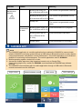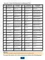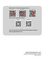
1
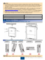
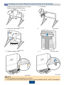
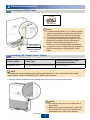
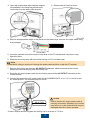
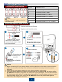
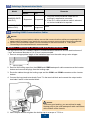
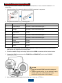
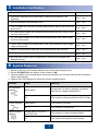
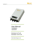
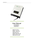
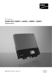
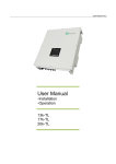
SUN2000-33KTL
Quick Installation Guide
Issue: 04
Part Number: 31507422
Date: 2015-09-15
HUAWEI TECHNOLOGIES CO., LTD.
NOTICE
1. The information in this document is subject to change without notice. Every effort has been
made in the preparation of this document to ensure accuracy of the contents, but all statements,
information, and recommendations in this document do not constitute a warranty of any kind,
express or implied.
2. Before installing the device, read the SUN2000-(33KTL, 40KTL) User Manual for knowledge of
product information and safety precautions. To obtain the user manual, log in to
http://support.huawei.com/carrier/ and browse or search for SUN2000 on the Product Support
page.
3. Install and use the device according to this document and the user manual. Otherwise, the
device may be damaged. Use insulated tools when installing the device.
Inverter Model
SUN2000-33KTL
Weight
50 kg
Dimensions (H x W x D)
770 mm x 550 mm x 270 mm
1
System Installation
1.1 Determining the Installation Position (Unit: mm)
Installation dimensions
Chassis dimensions
1.1 Determining the Installation Mode
Vertical
Backward
Forward
Horizontal
Upside down
NOTE
In a vertical support, install the device vertically or with a backward tilt of no more than 15 degrees.
1
Copyright © Huawei Technologies Co., Ltd. 2015. All rights reserved.
1.3 Installing an Inverter (Support-mounting Used as an Example)
2. Drill holes.
1. Determine the hole positions on the support
based on rear panel dimensions.
Unit: mm
3. Secure the rear panel.
4. Mount the inverter on the rear panel.
M12 (3 PCS)
45 N·m
5. Tighten hexagon bolts.
6. (Optional) Install an anti-theft lock.
NOTE
1. The anti-theft lock is prepared by the customer.
2. For details about how to wall-mount the device, see the SUN2000-(33KTL, 40KTL) User Manual.
2
2 Electrical Connection
2.1 Installing a PGND Cable
OT-M6
OT-M6
PE terminal
NOTE
M6 (1 PCS)
5 N·m
1. It is recommended that 8 mm 2 (8 AWG) outdoor
copper-core cables be used as ground cables.
Ground cables must be securely connected.
2. It is recommended that the ground cable be
connected to a nearby ground position. For a
system with multiple inverters connected in
parallel, connect the ground points of all
inverters to ensure equipotential connections.
3. To prevent corrosion, apply silica gel or paint to
the PE terminal after connecting the PGND
cable.
2.2 Installing AC Output Power Cables
OT-M6
Inverter Model
Cable Type
Cross-sectional Area of the
Cable (Recommended)
SUN2000-33KTL
4-core outdoor cable (L1, L2, L3, N)
16 mm2 (6 AWG)
NOTE
The table lists only the recommended cable specifications. For more information about cable
specifications, see the SUN2000-(33KTL, 40KTL) User Manual.
1. Remove the two screws from the chassis door using a hex key and set them aside.
NOTICE
1. Do not open the door on the upper side of
the inverter.
2. Before opening the chassis door, switch off
the upstream DC input circuit breaker and
downstream AC output circuit breaker.
3
2. Open the chassis door and install the support
rod available in the fitting bag bound to the
reinforcing rib at the base of the chassis.
3. Remove the AC terminal cover.
4. Remove an appropriate length of the jacket and insulation layer from the AC output cable using
a wire stripper.
5. Insert the exposed core wires into the crimp area of the OT terminal and crimp them using
hydraulic pliers.
6. Wrap the wire crimp area with heat shrink tubing or PVC insulation tape.
NOTE
If heat shrink tubing is used, put it through the power cable and then crimp the OT terminal.
7. Remove the locking cap from the AC OUTPUT waterproof cable connector at the inverter
bottom and remove the plug from the locking cap.
8. Route the AC output power cable into the locking cap and the AC OUTPUT connector at the
inverter bottom.
9. Connect the wires of the AC output cable for the SUN2000-33KTL to L1, L2, L3, and N on the
AC terminal block. The required torque is 4 N·m.
NOTICE
Ensure that the AC output power cable is
securely connected. Otherwise, the inverter
may fail to run or the terminal block may be
damaged after the inverter operates.
M6 (4 PCS)
4 N·m
10.Use a torque wrench to tighten the locking cap to a torque of 7.5 N·m.
4
2.3 Installing DC Input Power Cables
Optional DC input terminals
NOTE
Routes 1, 2, 3, 4, 5, and 6 are defined
from left to right.
Number of
Inputs
SUN2000-33KTL
1
Connects to any one route
2
Connects to routes 1 and 3
3
Connects to routes 1, 3, and 5
4
Connects to routes 1, 2, 3, and 5
5
Connects to routes 1, 2, 3, 4, and 5
6
Connects to routes 1, 2, 3, 4, 5, and 6
Positive and negative metal terminals
Positive metal terminal (female)
Negative metal terminal (male)
Positive metal terminal
Negative metal terminal
Common PV cables with a
cross-sectional area of 4 mm²
are recommended.
Recommended: H4TC0001
(Amphenol)
Ensure that cables cannot
be removed after crimped.
Positive connector
Ensure that the
locking nut is
secured.
Negative
connector
Click
Recommended: H4TW0001
(Amphenol)
NOTICE
1. Before connecting DC input power cables, mark the polarities on the cables to ensure that the
cables are connected correctly. If the cables are connected incorrectly, the device may be
damaged.
2. Check that DC input power cables will not be disconnected by pulling them.
3. If DC input power cables are reversely connected and the DC switch is ON, do not turn off the
DC SWITCH immediately. Otherwise, the equipment may be damaged. You can disconnect the
DC input power cable on the PV string side or wait until the PV string voltage reduces to a value
within the safety range. Then, turn off the DC SWITCH, remove the positive and negative
connectors, and rectify the connection.
5
2.4 Selecting a Communication Mode
Communication Mode
Model
Remarks
RS485
PLC
SUN2000-33KTL
(with PLC)
Supported
Supported
1. Only one communications mode can be
selected in application scenarios.
2. If the PLC communications mode is selected,
no device installation is required.
SUN2000-33KTL
(without PLC)
Supported
Not
supported
None.
2.5 Installing RS485 Communications Cables
NOTICE
1. When routing communications cables, ensure that communications cables are separated from
power cables and away from interfering source to prevent communication from being affected .
2. RS485 Communications cables can be connected to the terminal block or RJ45 ports.
Connecting to the terminal block is recommended.
Method 1: Connecting to the Terminal Block (Recommended)
The DJYP2VP2-22 2*2*1 network cable or a communications cable with a cross sectional area of
1 mm2 and external diameter of 14-18 mm is recommended.
1. Remove an appropriate length of the insulation layer from the cable using a wire stripper.
2. Remove the locking caps from the COM1 and COM2 waterproof cable connectors at the inverter
bottom and remove the plugs from the locking caps.
3. Route the cables through the locking caps and the COM1 and COM2 connectors at the inverter
bottom.
4. Connect the input end to terminals 5 and 7 in the terminal block and connect the output end to
terminals 6 and 8 in the terminal block.
NOTICE
To ensure good sealing, you are advised to apply
firestop putty to the used waterproof cable connectors
at the bottom of the chassis.
5. Use a torque wrench to tighten the locking cap to a torque of 7.5 N·m.
6
Method 2: Connecting to RJ45 Ports
Recommended outdoor network cable: cable outer diameter < 9 mm; internal resistance ≤ 1.5
ohms/10 m.
1. Insert the wires of the network cable to the RJ45 connector in sequence.
2. Crimp the connectors using a crimping tool.
No.
Color
Pin Definition
1
White-orange
RS485A, RS485 differential signal +
2
Orange
RS485B, RS485 differential signal -
3
White-green
PGND
4
Blue
RS485A, RS485 differential signal +
5
White-blue
RS485B, RS485 differential signal -
6
Green
PGND
7
White-brown
PGND
8
Brown
PGND
3. Remove the locking caps from the COM1 waterproof cable connectors at the inverter bottom
and remove the plugs from the locking caps.
4. Route the cables through the locking caps and the COM1 connectors at the inverter bottom.
5. Connect the RJ45 connectors to the RS485 IN and RS485 OUT ports in the SUN2000
maintenance area.
NOTICE
1. Block the unused RS485 ports with waterproof
plugs.
2. To ensure good sealing, you are advised to apply
firestop putty to the used waterproof cable
connectors at the bottom of the chassis.
6. Use a torque wrench to tighten the locking cap to a torque of 7.5 N·m.
7
3
Installation Verification
1. The SUN2000 is installed correctly and securely.
Yes □ No □
2. All screws, especially the screws used for electrical connections, are
tightened.
Yes □ No □
3. All circuit breakers are switched to OFF.
Yes □ No □
4. Ground cables are connected correctly and securely, with no open circuit or
short-circuit.
Yes □ No □
5. AC output power cables are connected correctly and securely, with no open
circuit or short-circuit.
Yes □ No □
6. DC input power cables are connected correctly and securely, with no open
circuit or short-circuit.
Yes □ No □
7. The DC input voltage is not higher than 1000 V and meets the local voltage
range requirements.
Yes □ No □
8. RS485 communications cables are connected correctly and securely.
Yes □ No □
9. Idle DC input terminals are sealed.
Yes □ No □
10.Idle USB and RS485 ports and waterproof connectors are plugged with
waterproof plugs.
Yes □ No □
4
System Power-on
1. Switch on the AC circuit breaker between the inverter and the power grid.
2. Set the DC SWITCH at the bottom of the inverter to ON.
3. (Optional) Measure the temperatures at the joints between the DC terminals and the connectors
using a thermometer.
4. Observe the LED indicators to check the inverter operating status.
Indicator
Status
Meaning
PV connection
indicator
Steady green
At least one PV string is properly connected,
and the DC voltage exceeds 200 V.
Off
The inverter is disconnected from all PV strings.
Steady green
The inverter is grid-tied.
Off
The inverter is not grid-tied.
Blinking green (on for 0.5s
and off for 0.5s)
The inverter is communicating properly.
Off
The inverter has failed to communicate.
Grid-tie indicator
Communication
indicator
8
Indicator
Status
Alarm/
Maintenance
indicator
Alarm state
Meaning
Blinking red slowly (on
for 1s and then off for 4s)
The inverter has generated a warning.
Blinking red fast (on for
The inverter has generated a minor
0.5s and then off for 0.5s) alarm.
Local
maintenanc
e state
5
Steady red
The inverter has generated a major
alarm.
Blinking green slowly (on
for 1s and then off for 1s)
Local maintenance is in progress.
Blinking green fast (on
for 0.125s and off for
0.125s)
Local maintenance has failed.
Steady green
Local maintenance is successful.
SUN2000 APP
NOTE
1. The SUN2000 application is a mobile application that enables the SUN2000 to communicate
with the SUN2000 monitoring system through a USB cable or Bluetooth module to query alarms,
configure parameters, and perform routine maintenance. The mobile application is a convenient
platform for monitoring and maintenance. The mobile application name is SUN2000.
2. Mobile operating system: Android 4.0 or later.
3. Access the Huawei app store (http://appstore.huawei.com) or Google Play
(https://play.google.com), search for SUN2000, and download the SUN2000 app software
package.
4. The SUN2000 communicates with its mobile application through a USB cable or Bluetooth
module connected over the USB port.
Login screen
Switch between users
Main menu
9
Quick settings
NOTICE
The initial password for Common User, Advanced User, and Special User is 000001 or 00000a.
Use the initial password to log in to the inverter for the first time and change the password
immediately to ensure account security.
NOTE
1. Tap
to return to the login screen.
2. Inverter grid connection setup requires no parameter setting by default. The parameters can be
adjusted based on site requirements. For parameter settings, see the SUN2000-(33KTL, 40KTL)
User Manual.
10
Appendix: Power Grid Standard Code Mapping Table
No.
Power Grid
Standard Code
Country and
Condition
No.
Power Grid
Standard Code
Country and
Condition
1
NB/T 32004
China low-voltage
power grid
2
VDE-AR-N-4105
Germany low-voltage
power grid
3
EN50438-NL
Netherlands lowvoltage power grid
4
BDEW-MV
Germany mediumvoltage power grid
5
UTE C 15-7121(A)
France low-voltage
power grid
6
EN50438-CZ
Czech Republic lowvoltage power grid
7
UTE C 15-7121(B)
Islands of France
230 V 50 Hz
8
TAI-PEA
Thailand low-voltage
power grid (PEA)
9
UTE C 15-7121(C)
Islands of France
230 V 60 Hz
10
TAI-MEA
Thailand low-voltage
power grid (MEA)
11
NRS-097-2-1
South Africa lowvoltage power grid
12
VDE 0126-1-1GR(A)
Mainland of Greece lowvoltage power grid
13
KOREA
South Korea lowvoltage power grid
14
VDE 0126-1-1GR(B)
Islands of Greece lowvoltage power grid
15
G59-England
England 230 V
power grid (I > 16
A)
16
RD1699
Spanish low-voltage
power grid (Pn < 100 kW)
17
G59-Scotland
Scotland 240 V
18
power grid (I > 16 A)
RD661
Spanish low-voltage
power grid (Pn > 100 kW)
19
G83-England
England 230 V
20
power grid (I < 16 A)
VDE 0126-1-1-BU
Bulgaria low-voltage
power grid
21
G83-Scotland
Scotland 240 V
22
power grid (I < 16 A)
AS4777
Australia low-voltage
power grid
23
CEI0-21
Italian low-voltage
power grid
24
EN50438-TR
Turkey low-voltage
power grid
25
CEI0-16
Italian mediumvoltage power grid
26
C10/11
Belgium low-voltage
power grid
27
Philippines
Philippines lowvoltage power grid
28
Custom(60Hz)
Reserved
29
IEC61727
IEC low-voltage
power grid
30
Custom(50Hz)
Reserved
31
IEC61727-60Hz
IEC low-voltage
power grid (60 Hz)
N/A
N/A
N/A
NOTE
Grid codes are subject to change. The listed codes are for your reference only.
For more information, refer to the channels provided on the following page.
11
Scan here for technical support (carrier):
App Store
Google Play
Huawei App Store
Scan here for more documents:
Support
WeChat
You can also log in to Huawei technical support website:
http://support.huawei.com
Huawei Technologies Co., Ltd.
Huawei Industrial Base, Bantian, Longgang
Shenzhen 518129 People's Republic of China
www.huawei.com
12