1
US007526737B2
(12) Ulllted States Patent
(10) Patent N0.:
Simmons et a].
(54)
45 Date of Patent:
FREE FORM WIPER
5,442,742 A
5,446,882 A
(75)
US 7,526,737 B2
Inventors: Alex J- Simmons, Redmond, WA (US);
Benoit Barabe, SI10q11a1m1e,WA(US)
A r. 28 a 2009
8/1995 Greyson et a1. ........... .. 715/539
8/1995
Capps et al. ........... .. 707/104.1
5,465,325 A
11/1995 Capps et a1. .............. .. 345/441
5,477,447 A
12/1995 Luciw et a1. ................. .. 704/9
(73) Assignee: Microsoft Corporation, Redmond, WA
(Us)
(*)
Notice:
Subject to any disclaimer, the term of this
patent is extended or adjusted under 35
U.S.C. 154(b) by 501 days.
(Continued)
FOREIGN PATENT DOCUMENTS
DE
40 26 852 Al
21991
(21) App1.No.: 11/272,960
(22)
Filed:
Nov. 14, 2005
(65)
_
(Continued)
Prior Publication Data
US 2007/0109281 A1
OTHER PUBLICATIONS
May 17, 2007
_
_
_
_
_
_
Ken Hmckley et a1. “Deslgn and analys1s of dellmlters for selectlon
(51)
Int- Cl-
action pen gesture phrases in scriboli” Apr. 2005 10 pages.*
G09G 5/00
G06F 17/00
G06F 3/00
(52)
(2006.01)
(2006.01)
(2006.01)
C td
( on “me )
Primary ExamineriKieu D Vu
US. Cl. ..................... .. 715/856; 345/173; 345/ 174;
AssistantExamineriHaoshian Shih
345/175; 345/179; 715/862; 715/863
(58)
Field of Classi?cation Search ............... .. 715/770,
715/863, 856, 862; 345/170, 173, 174, 175,
345/179’ 419
See application ?le for complete search history.
(56)
References Cited
5,063,376
A
5,063,600 A
5,133,076 A
5,231,698
A
Chang
.. ... ... .
7/1993
Forcier
. ... .. ... ..
6/1994 Fenrich et a1.
5,327,342
7/1994
A
5,347,295 A
5,367,453 A
5,390,281 A
5,404,442 A
5,434,929 A
. . . ..
11/1991 Norwood .
7/1992 Hawkins et a1. .
5,321,768 A
Roy
9/1994 Agulnick et a1.
11/1994 Capps et a1.
2/1995
4/1995
7/1995
345/163
345/173
708/141
. . . ..
715/541
. . . ..
345/467
382/178
. . . . . . . . . . . . . . .
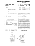
ABSTRACT
Wipe selection may be determined by analyzing the shape of
7/1944 Polydoroff ................ .. 343/788
11/1991
(57)
A free-form Wiper tool may be used to select and move
document objects in an electronic document. A free-form
U.S. PATENT DOCUMENTS
2,354,332 A
(74) Attorney, Agent, or FirmiMerchant & Gould; Ryan T.
Grace
345/156
715/531
LuciW et a1. ................ .. 395/12
Foster et a1. .............. .. 395/159
Beernink et a1. .......... .. 382/187
Here is some text.
a free-form selection in order to distinguish it from a free
form lasso selection. Once determined, document objects
situated on the document in an intended direction are
selected. The group of selected objects may be moved,
although selected objects may be restricted in their move
ment, so as to be Wiped or moved along only one degree of
motion. Selection input may be made using a stylus and a
tablet computer, and document objects may include elec
tronic ink.
20 Claims, 11 Drawing Sheets
US 7,526,737 B2
Page 2
US. PATENT DOCUMENTS
5,479,596 A
6,348,935 B1
3/2002
Butcher .... ..
6,380,957 B1
4/2002
Banning ................... .. 715/828
12/1995
CaPPS er a1- -------------- -- 715/539
5491495
5500937
5,513,309
5517578
A
A
A
A
5,523,775 A
2/1996
3/1996
4/1996
5/1996
345/173
715/764
715/860
382/181
6,487,567
6,487,569
6,529,215
6,546,397
5,528,743 A
6/1996 Toll etal -
345/179
715/541
6,559,871 B1
6,565,611 B1
Ward eta1~
Thompson-Rohrlich
Meier et a1. ............... ..
Altman etal
6/1996 Capps ......... ..
..
2/2002 Malacinski et a1. ....... .. 715/853
6,355,889 B1
B1
B1
B2
B1
11/2002
11/2002
3/2003
4/2003
. 178/18.03
Michelman et a1. ....... ..
Lui et a1. ............ ..
Golovchinsky et a1‘
Rempell ................... ..
715/525
715/530
715/764
707/102
5/2003 Brozowskiet a1
715/g53
5/2003 Wilcox etal. ............. .. 715/541
5544295 A
8/1996 CaPPS
345/473
6,570,596 B2
5/2003 Frederiksen .............. .. 715/808
5,544,358 A
8/1996 Capps eta1~
715/523
6,594,390 B2
7/2003 Frinketal. ..
5,555,363 A
9/1996
Toll etal ----- -~
715/541
6,650,347 B1
11/2003
Nulu et a1. ................ .. 715/853
9/1996 Gough eta1~ -~
Thomason et a1. ........ .. 715/541
5,559,942 A
382/187
715/802
6,651,221 B1
11/2003
5,561,446 A
10/1996 Montlick
345/173
6,654,035 B1
11/2003 Destefano
5579467 A
11/1996
715/507
6,661,409 B2
12/2003
5583542 A
5,588,105 A
12/1996 CaPPS er a1
12/1996 Foster et al.
345/173
6,678,865 B1
1/2004 Pratley et a1. ............. .. 715/509
715/779
6,681,045 B1
1/2004 Lapsmn et a1‘
5,590,257 A
12/1996
715/530
6,683,600 B1
1/2004
CaPPS ------ --
Forcier ........ ..
_715/798
Deninnines et a1. ....... .. 345/173
Lui ____ __
3g2/1g7
_345/179
5,592,566 A
1/1997 Pagallo et a1. ..
382/187
6,690,364 B1
2/2004 Webb
5,594,640 A
5596350 A
1/1997 Capps et a1.
V1997 CaPPS er a1
715/532
6,727,927 B1
4/2004 Dempskiet 31‘
-- 345/173
6,741,749 B2
5/2004
5596694 A
5596697 A
V1997 CaPPS ------ -V1997 Fosteretal'
345/473
715/810
6,801,190 B1
6,833,827 B2
10/2004 Robinson et al.
12/2004 Luietal. ......... ..
345/173
345/173
5602570 A
5,613,019 A
2/1997 CaPPS er a1
3/1997 Altman etal
345/173
382/311
6,836,759 B1
6,859,909 B1
12/2004 Williamson etal.
2/2005 Lerneretal.
704/235
715/512
5,634,102 A
5/1997 CaPPS ------ --
715/744
6,989,822 B2
1/2006 Pettiross et al
5,649,133 A
7/1997 Arquie
715/764
7,002,560 B2
2/2006 Graham
HerbeI‘t,Jr.
_345/173
75/55}
. 382/246
345/179
.345/179
5,655,136 A
8/1997 Morgan ....... ..
382/187
7,039,234 B2
5/2006 Geidlet a1,
5,666,139 A
9/1997 Thielens et al.
345/173
7,055,110 B2
5/2006 Kupka
5,666,552 A
9/1997 Greyson et a1.
715/539
7,079,713 B2
7/2006 Simmons _
_3g2/321
5,671,438 A
9/1997 CaPPS er a1- ---- --
715/539
7,091,959 B1
8/2006
Clary ....... ..
.345/173
382/187
382/189
715/777
345/442
715/808
7,096,432
7,174,042
7,185,278
7,188,309
7,240,300
g/2006
2/2007
2/2007
3/2007
7/2007
Huapaya et a1‘ _
Simmons etal,
Simmons ..... ..
Simmons et al‘
Jaeger
715/g63
3g2/1g7
.715/235
715/244
_ 715/863
5,682,439
5,710,831
5,745,716
5,757,383
5,760,773
A
A
A
A
A
10/1997
1/1998
4/1998
5/1998
6/1998
Beernink et a1. ..
Beerninket a1. ..
T911219 9ta1~
Lipton ......... ..
Berman et a1. .
B2
B1
B1*
B2
132*
5,764,818 A
6/1998 Capps et a1.
382/317
7,259,752 B1
g/2007 Simmons
5,768,418 A
6/1998 Berman et a1. .
382/187
7,259,753 B2
g/2007 Keely et 31
5,778,404 A
5,796,397 A
7/1998 Capps et a1. .............. .. 715/531
8/1998 Kusano .................... ..
7,353,453 B1
7,358,965 B2
21/2008 Simmons
21/2008 Barabe et a1,
7,370,288 B1
5/2008 Simmons et al.
5,809,498 A
5,838,326 A
5,838,819 A
9/1998 Loprestietal
11/1998 Card et a1. ................ ..
11/1998 Ruedisueliet a1. ........ .. 382/187
5,864,635 A
V1999
5,867,150 A
5,874,957 A
2/1999 Bricklin .................... .. 345/173
2/1999 Clineetal. ............... .. 715/786
2001/0000960
2002/007g035
2002/0097270
2002/0126153
2003/0066031
5,880,743 A
3/1999 Moran et a1.
345/473
2003/0071850 A1
4/2003 Geidl
5,911,145 A
5,953,735 A
6/1999 Aroraetal. ............... .. 715/514
9/1999 Forcier ..................... .. 715/541
2003/00g5931 A1
2003/0119469 A1
5/2003
6/2003
Zens er a1- ------ -
A1
A1
A1
A1
A1
5/2001
6/2002
7/2002
9/2002
4/2003
Dettloff
Franketal,
Keely et a1. ..
Withers et 31,
Laane
Cardetal,
Kan et a1‘ _
5963208 A
10/1999 13919119491
715/760
2003/0214491 A1
11/2003 Keely et a1. ..
5,970,455 A
5,993,391 A
10/1999 Wilcox etal. ............. .. 704/270
11/1999 Kamiyama ................ .. 345/607
2003/0214531 A1
2003/0215142 A1
11/2003 Chambers etal,
11/2003 Gounares
_345/173
345/179
_715/26g
345/179
715/854
_343/74g
707/3
345/764
345/773
_715/513
_345/7g1
345/g53
455/307
345/179
345/764
_3g2/19()
6,020,895 A
2/2000
AZami ------ -~
2003/0227491 A1
12/2003
Moehrle ................... .. 345/854
6,021,218 A
2/2000
Capps er a1 -------------- -- 382/187
2004/0003350 A1
1/2004
Simmons et a1. .......... .. 715/517
6,035,324 A
3/2000 Chang et a1. .............. .. 709/203
2004/0021701 A1
2/2004 lwemaetal,
6,061,472 A
5/2000 Hullender er a1- -
2004/0060000 A1
3/2004
Jaeger ...................... .. 715/502
Fitzmaurice .............. .. 345/856
6,069,626 A
5/2000
6,081,829 A
6/2000 Sidana
6,108,445 A
6,128,007 A
Cline eta1~
-
3g2/1g7
_715/g63
--------------- -- 715/786
2004/0135824 A1
7/2004
709/203
2004/0141015 A1
7/2004 Fitzmaurice et a1.
8/2000 Uehara
10/2000 Seybold .................... .. 345/179
2005/0028081 A1
2005/0179647 A1
2/2005
g/2005
345/g63
345/856
AICUIi et a1. ........... .. 715/501.1
Simmons et a1, __________ __ 345/156
6,128,633 A
10/2000 Mlchelman etal. ....... .. 715/525
2005/0183029 A1
g/ZOOS Barabe et a1‘
6,154,219
6,154,758
6,188,405
6,199,125
A
A
B1
B1
11/2000
11/2000
2/2001
3/2001
Wiley eta1~ ----- Chiang --------------------- -- 715/541
CZerWinski et a1. ....... .. 715/764
Cortesi -------- --
2005/0206627 A1
9/2005
Simmons .................. .. 345/179
1/2006
10/2006
11/2006
LaViola etal. ............ .. 345/179
Simmons _____ __
_3g2/321
Hinckleyet a1. .......... .. 345/179
6,223,145 B1
6,243,258 B1
6,279,014 B1
4/2001
6/2001
8/2001
361/680
715/512
6,295,372
6,304,272
6,337,698
6,340,967
6,345,389
B1
B1
B1
B1
B1
9/2001
10/2001
1/2002
1/2002
2/2002
Hawkins et a1. ........... ..
Schanel et a1. ............ ..
Keely, Jr. et a1. .......... ..
Maxted .................... ..
Dureau ..................... ..
382/187
345/676
715/823
345/179
725/116
2006/0001656 A1*
2006/0233464 A1
2006/0267967 A1*
FOREIGN PATENT DOCUMENTS
EP
EP
EP
EP
EP
0460420
0780 797
1376 390
1450294
1486883
A2
A
A
A1
A2
12/1991
6/1997
1/2004
8/2004
12/2004
715/779
US 7,526,737 B2
Page 3
GB
JP
2 313 993 A
3-270403
12/1997
12/1991
OTHER PUBLICATIONS
Wilcox et al., “Dynomite: A Dynamically Organized Ink and Audio
Notebook,” Computer-Human Interaction, Mar. 27, 1997, pp. 186
193.
U.S. Of?cial Action mailed Mar. 1, 2006, in U.S. Appl. No.
10/186,837.
U.S. Of?cial Action mailed May 25, 2005, in U.S. Appl. No.
10/186,837.
U.S. Of?cial Action mailed Mar. 13, 2006, in U.S. Appl. No.
10/186,812.
U.S. Of?cial Action mailed Jul. 13, 2005, in U.S. Appl. No.
Jakobsen, T., “Advanced Character Physics,” Game Developer’s
10/186,812.
Conference, 2001 Proceedings, pp. 1-17.
FitZmaurice et al., “Tracking Menus,” CHI 2003, vol. 5, No. 2, pp.
71-80, 2003.
U.S. Of?cial Action mailed Aug. 5, 2008, in U.S. Appl. No.
U.S. Of?cial Action mailed Feb. 28, 2005, in U.S. Appl. No.
10/781,489.
U.S. Of?cial Action mailed Sep. 20, 2005, in U.S. Appl. No.
10/186,812.
U.S. Of?cial Action mailed Apr. 21, 2006, in U.S. Appl. No.
10/186,865.
U.S. Appl. No. 10/780,366 ?led Feb. 17, 2004, entitled “Writing
10/186,865.
Guide for a Free-Form document Editor”, Inventors: AleX Simmons
et al.
U.S. Of?cial Action mailed Aug. 22, 2007, in U.S. Appl. No.
U.S. Of?cial Action mailed Nov. 19, 2008, in U.S. Appl. No.10/
U.S. Of?cial Action mailed Jan. 3, 2007, in U.S. Appl. No.
10/186,874.
804,616.
10/186,874.
U.S. Of?cial Action mailed Jan. 10, 2008, in U.S. Appl. No.
U.S. Of?cical Action mailed Aug. 10, 2006, in U.S. Appl. No.
10/804,616.
10/186,874.
U.S. Of?cial Action mailed Jul. 12, 2007, in U.S. Appl. No.
U.S. Of?cial Action mailed Jun. 29, 2005, in U.S. Appl. No.
10/804,616.
10/186,874.
U.S. Of?cial Action mailed Aug. 5, 2008, in U.S. Appl. No.
U.S. Of?cial Action mailed Sep. 15, 2006, in U.S. Appl. No.
10/781,489.
U.S. Of?cial Action mailed Dec. 27, 2007, in U.S. Appl. No.
10/781,489.
U.S. Of?cial Action mailed Jun. 28, 2007, in U.S. Appl. No.
10/781,489.
U.S. Of?cial Action mailed Nov. 7, 2006, in U.S. Appl. No.
10/781,489.
U.S. Of?cial Action mailed Apr. 20, 2006, in U.S. Appl. No.
10/781,489.
U.S. Of?cial Action mailed Aug. 20, 2008, in U.S. Appl. No.
10/780,366.
U.S. Of?cial Action mailed Nov. 14, 2007, in U.S. Appl. No.
10/780,366.
U.S. Of?cial Action mailed Sep. 20, 2005, in U.S. Appl. No.
10/186,463.
10/186,847.
U.S. Of?cial Action mailed Jan. 27, 2006, in U.S. Appl. No.
10/186,847.
U.S. Of?cial Action mailed Jul. 27, 2005, in U.S. Appl. No.
10/186,847.
U.S. Of?cial Action mailed Nov. 12, 2008, in U.S. Appl. No.
10/782,133.
U.S. Of?cial Action mailed Feb. 20, 2008, in U.S. Appl. No.
10/782,133.
U.S. Of?cial Action mailed Sep. 18, 2007, in U.S. Appl. No.
10/782,133.
U.S. Of?cial Action mailed Mar. 2, 2007, in U.S. Appl. No.
10/782,133.
U.S. Of?cial Action mailed Jan. 3, 2007, in U.S. Appl. No.
U.S. Of?cial Action mailed May 18, 2007, in U.S. Appl. No.
10/782,132.
10/186,820.
Microsoft Word 2000, Microsoft Corporation (9.0.6926 sp-3).
U.S. Of?cial Action mailed Nov. 24, 2006, in U.S. Appl. No.
European Search Report dated Nov. 11, 2005.
Wacom Intuos TM User’s Manual for Windows, May 22, 2000,
copyright Wacom Company, Ltd., pp. 1-165 (Part 1: pp 1-60: Part 2:
10/186,820.
U.S. Of?cial Action mailed Nov. 9, 2006, in U.S. Appl. No.
10/186,820.
U.S. Of?cial Action mailed Mar. 2, 2006, in U.S. Appl. No.
10/186,820.
pp. 61-120 ; Part 3: pp. 121-165).
U.S. Of?cial Action mailed Dec. 17, 2004, in U.S. Appl. No.
10/186,837.
U.S. Of?cial Action mailed Aug. 10, 2005, in U.S. Appl. No.
10/186,820.
* cited by examiner
US. Patent
Apr. 28, 2009
Sheet 1 0f 11
[1/08
US 7,526,737 B2
COMPUTING DEVICE
5104
/ATAA
OM
M“ETBTR
ORPSKDID:MGOEYELUEM
MMS
0MNw
ROP
NM
MNMwDY
S
A
G
N
D. R O
f\///
8WG
CU ENSW
wHUE
_NW.|)_ ._E )E
MOUvE0NVUEnvvRTmPmNCMR
N_SMNDESOEMNTRTIE PEUEAA0AmlvW6
T6AmT56VG
OR
C
N
OC0
PA|
DNT
W8
L
A
1181
FIG. 1
OTHER
COMPUTING
DEVICES
4.6290
M
HO
US. Patent
Apr. 28, 2009
Sheet 2 0f 11
US 7,526,737 B2
200
201
203
FIG. 2
US. Patent
Apr. 28, 2009
Sheet 3 0f 11
FIG. 3
FIG. 4
US 7,526,737 B2
US. Patent
Apr. 28, 2009
Sheet 4 0f 11
FIG. 5
FIG. 6
US 7,526,737 B2
US. Patent
Apr. 28, 2009
Sheet 5 0f 11
US 7,526,737 B2
705
Here is some text.
701
706
27411775“; 707
t
FIG. 7
f.
702
704
Here is some text.
819
701
____‘
FIG. 8
702
704
Here is some text.
FIG. 9
Here is some more text.
US. Patent
CDU'l-BONA
CDU'IAON
CDU‘I-hONA
Apr. 28, 2009
Sheet 6 0f 11
US 7,526,737 B2
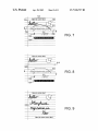
Lorem ipsum dolor sit amet, consectetuer
adipiscing elit. Praesent egestas mattis neque.
Vestibulum interdum di m non felis. Sed augue
——-—-->
lorem, egestas por‘ttitor, egestas rhoncus, vulputate
vel, nunc. Vestibulum s d dolor ut quam bibendum
interdum. Nunc convallis, nulla id venenati.
FIG. 10
Lorem ipsum dolor sit amet, consectetuer
adipiscing elit. Praesent egestas mattis neque.
Vestibulum interdum diam non felis. Sed augue
lorem, egestas porttitor,
vulputate vel, nunc. Vestibulum sed dolor ut quam
bibendum interdum. Nunc convallis, nulla id venenati.
FIG. 11
Lorem ipsum dolor sit amet, consectetuer
adipiscing elit. Praesent egestas mattis neque.
Vestibulum interdum diam non felis. Sed augue
lorem, egestas porttitor, [Lt-12L egestas rhoncus,
vulputate vel, nunc. Vestibulum sed dolor ut quam
bibendum interdum. Nunc convallis, nulla id venenati.
FIG. 12
US. Patent
Apr. 28, 2009
v
A
J
704 \\
Sheet 7 0f 11
US 7,526,737 B2
71/1
/~
/£ 7150“
1306
Here k
{I131 1
FIG. 13
Here is some text.
some more text.
1306
FIG. 14
US. Patent
Apr. 28, 2009
H e r e .S
Sheet 8 0f 11
US 7,526,737 B2
s 0 m e t e xL
some more text.
FIG. ‘I5
Here is some text.
AA
A
7"
'M
/
Here is
some more text.
FIG. 16
US. Patent
Apr. 28, 2009
Sheet 9 0f 11
US 7,526,737 B2
/-\/
RECEIVE
SELECTION
COMMAND
I
1702
/\_/
RECEIVE
FREE-FORM
INPUT
HORIZ.
OR VERT.?
1706
LEFT OR
RIGHT?
1708
1705
,\/
,\/
SELECT
OBJECTS BELOW
WIPER
SELECT
OBJECTS
TO THE LEFT
I
RECEIVE
SELECTION
MOVEMENT
I
MOVE
OBJECTS
ACCORDINGLY
FIG. 17
@
1710
/\/
SELECT
OBJECTS
TO THE RIGHT
US. Patent
Apr. 28, 2009
Sheet 10 0f 11
US 7,526,737 B2
1808a
l
1803a|
gay/M4
FIG. 18A
1802 1807
1801
FIG. 18C
US. Patent
Apr. 28, 2009
Sheet 11 0f 11
I
US 7,526,737 B2
1901
RECEIVE
SELECTION
COMMAND
I
A}902
RECEIVE
FREE-FORM
INPUT START
I
A1903
DETERMINE
DIRECTION
FOR START RAY
I
A1/904
RECEIVE
FREE-FORM
INPUT END
I
1905
/\/
DETERMINE
DIRECTION
FOR END RAY
I
/\1/906
SELECT
OBJECTS
BETWEEN RAYS
I
A}907
RECEIVE
SELECTION
MOVEMENT
I
MOVE
OBJECTS
ACCORDINGLY
FIG. 19
@
1908
/'\/
US 7,526,737 B2
1
2
FREE FORM WIPER
example, changing which side of a selection path should be
selected based on cursor movement.
RELATED APPLICATIONS
BRIEF DESCRIPTION OF THE DRAWINGS
This patent application is related to co-pending non-provi
The foregoing brief summary of the invention, as well as
sional US. patent application Ser. No. 10/ 186,837 entitled
“Space Management for Electronic Documents,” which is
the following detailed description, is better understood when
read in conjunction with the accompanying drawings, which
are included by way of example, and not by way of limitation
with regard to the claimed invention. In the accompanying
hereby incorporated by reference.
BACKGROUND
drawings, the same or similar elements are labeled with the
same reference numbers.
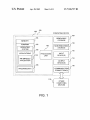
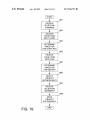
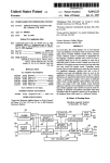
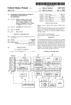
FIG. 1 depicts an exemplary operating environment in
Whether for word processing, note taking, slide presenta
tions, or graphics editing, nearly every computer user has
which one or more embodiments may be implemented.
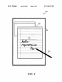
FIG. 2 depicts an exemplary operating environment in
edited a document at one time or another. Although initially
which one or more embodiments may be implemented.
purely text-based, software applications for editing docu
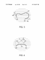
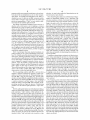
FIGS. 3 and 4 depict free-form selection boundaries
ments have greatly bene?ted from the advent of graphical
according to one or more embodiments of the invention.
operating systems. Interactive what-you-see-is-what-you-get
(WYSIWYG) interfaces and additional enhancements of
such operating systems have made software applications
20
FIGS. 7-9 depict document objects being selected and
more accessible and intuitive for average users.
Electronic ink interfaces in particular have enhanced the
common tasks associated with editing documents. Users have
bene?ted from the ability to interact directly with a computer
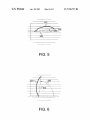
FIGS. 5 and 6 depict one embodiment for determining the
orientation of a wipe selection.
moved by a vertical wipe according to one or more embodi
ments.
FIGS. 10-12 depict text moved with a horiZontal wipe in
25 order to insert new text according to one or more embodi
display, easily handwriting, drawing ?gures, and otherwise
ments.
manipulating document objects using a stylus, ?nger, or other
implement. While similar to the point-and-click paradigm of
FIGS. 13-16 depict a collection of document obj ects, some
of which are wiped to the right and to the left, according to one
using a mouse, electronic ink makes many document-editing
tasks even easier, a prime example being handwriting.
or more embodiments.
30
Virtually every document-editing task associated with a
FIGS. ISA-18C depict a series of document objects being
point-and-click mouse or trackball has been replicated for use
with a stylus and electronic ink. As such, users may create text
and drawings, as well as select and manipulate objects using
a stylus and conventional editing tools. However, new para
dynamically selected by a selection path according to one or
more embodiments.
35
digms for editing documents may be made possible by elec
tronic ink. Such paradigms may allow for even faster and
more e?icient document editing, enabling users to, for
example, select and move several objects vertically or hori
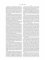
FIG. 17 is a ?owchart depicting a method for using a
free-form wiper tool according to one or more embodiments.
FIG. 19 is a ?owchart depicting a method for selecting
objects in a document using two rays according to one or
more embodiments.
DETAILED DESCRIPTION
40
Zontally on a page.
A free-form wiper tool may take advantage of the unique
Previously, a wiper bar tool has been described. Such tools
features of electronic ink, allowing for vertical or horizontal
may allow for objects in a document to be moved up or down
selection and movement of obj ects across an electronic docu
a page, extending page margins appropriately. A wiper tool
may be invoked by setting an insertion point and signaling a
wipe. Whereas the wiper bar tool may be useful for creating
ment. The results in the ?exible insertion of empty space into
which additional objects may be moved or created. A wipe
selection may be limited in the direction it can move, only
45
space on a page, it may not allow unrestricted wiping and may
horiZontally or vertically, for example. By analyZing the path
not fully take advantage of the unique features of electronic
of a stylus across a page, it can be determined whether a user
ink.
There is a need in the art for new document editing para
50
digms that leverage the unique features of electronic ink,
particularly for the unrestricted selection and movement of
determined. Providedbelow are examples and descriptions of
various embodiments of a free-form wiper, including
document objects.
55
SUMMARY
Methods and systems are provided for receiving a selection
input capable of selecting objects in a document within cer
tain portions of the document. A free-form selection path is
intends a wipe or lasso type selection. Further, it can be
determined whether a horiZontal or vertical wipe is intended,
and if horiZontal, whether the wipe will be to the left or the
right. Furthermore, a direction and distance of a wipe can be
examples of operating environments in which the wiper may
be implemented. Further, provided are examples of the meth
ods that may be used to implement the tool.
FIG. 1 depicts an exemplary operating environment in
which one or more embodiments may be implemented. The
60
operating environment may comprise computing device 100
entered by a user with a mouse, stylus, or other input device.
which may work alone or with other computing devices 118.
The path may be analyZed to determine whether it is intended
to be a free-form wipe, or other type of selection (e.g., lasso
selection). Next the path is analyZed to determine a direction
Computing device 100 may comprise memory storage 104
coupled to processing unit 102. Any suitable combination of
hardware, software, and/or ?rmware may be used to imple
ment memory 104, processing unit 102 and other compo
nents. By way of example, memory 104, processing unit 102,
of selection, whether above, below, to the left or right (or
quadrant subsets thereof) of the selection path. Users may
further modify selected objects with further input; for
65
and/or other components may be implemented within com
US 7,526,737 B2
3
4
puting device 100 as shown, or may be implemented in com
keyboards, mice, pens, microphone, touchpad, touch-display,
bination With other computing devices 118. The systems,
devices, and processors shoWn are used merely as examples
etc. Output devices 114 may include displays, speakers, print
ers, and so forth. Additional forms of storage, input, and
output devices may be utiliZed.
of embodiments.
Generally, program modules may include routines, pro
grams, components, data structures, and other types of struc
Computing device 100 may also include one or more com
munication connections 116 Which alloW the computing
device to communicate With other computing devices 118,
tures that perform particular tasks or implement particular
abstract data types. Moreover, embodiments may be prac
such as over a netWork (e.g., a local area netWork (LAN), the
ticed With other computer system con?gurations, including
Internet, etc.). Communication media, in the form of com
puter readable instructions, data structures, program mod
hand-held devices, multiprocessor systems, microprocessor
based or programmable consumer electronics, minicomput
ers, mainframe computers, set-top boxes, and so forth.
Embodiments may also be practiced in distributed computing
environments Where tasks are performed by other computing
ules, or other data in a modulated data signal, may be shared
With and by device 100 via communication connection 116.
Modulated data signal may mean a signal that has one or more
of its characteristics set or changed in such a manner as to
devices 118 that are linked through a communications net
encode information in the signal, and may include a modu
Work. In a distributed computing environment, program mod
ules may be located in both local and remote memory storage
devices.
Embodiments, for example, may be implemented as a
computer process or method (e.g., in hardWare or in soft
lated carrier Wave or other transport mechanism. Communi
cation connection 116 may be comprised of hardWare and/or
softWare enabling either a Wired (e.g., Ethernet, USB, Token
20
Ring, modem, etc.) or Wireless (e.g., WiFi, WiMax, cellular,
acoustic, infrared, radio frequency (RF), etc.) communication
Ware), a computing system, or as an article of manufacture,
such as a computer program product or computer readable
conduit With other devices 118.
media. The computer program product may be a computer
storage media readable by a computer system and encoding a
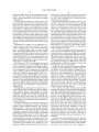
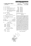
Which one or more embodiments may be implemented. In
computer program of instructions for executing a process on
FIG. 2 depicts an exemplary operating environment in
certain embodiments, tablet computer 200 may be an imple
25
mentation of generic computing device 100. Tablet computer
200 includes sensitive display 201, Which may be touch
sensitive and/or electro-magnetically sensitive. Other types
of sensing displays may also be used. Tablet computer 200
30
multiple WindoWs to display the interfaces of various soft
computing device 100. The computer program product may
also be a propagated signal on a carrier readable by a com
puting system and subsequently stored on a computer read
able medium on computing device 100.
With reference to FIG. 1, the embodiment shoWn may
include a computing device, such as computing device 100. In
a basic con?guration, computer device 100 may include at
least one processing unit 102, and memory 104. Depending
on the con?guration of the computer device, memory 104
may be volatile (e.g., Random Access Memory (RAM)), non
has a graphical operating system 105 installed, one that uses
Ware applications in use on the computer.
One piece of software installed on tablet computer 200 may
be an electronic ink-enabled application 120, for Which Win
doW 202 may be the visible interface on display 201. Elec
35
tronic ink is a term used generally to refer to handWritten
volatile (e.g., Read-Only Memory (ROM), Flash, etc.), or
input for use With computing devices. This input may be
some combination thereof. Memory 104 may serve as a stor
entered using a stylus (or other pointing implement) 203 in
age location for operating system 105, one or more applica
tions 106, and may include program data 107, as Well as other
programs. In one embodiment, applications 106 may include
proximity to a display, as displayed in FIG. 2. LikeWise,
electronic ink may be input using a touch pad, tablet, mouse,
or other input device alloWing free-hand input. Ink-enabled
40
operating systems and/or applications should generally be
an electronic ink-enabled application 120. Examples of oper
ating system 105 are found in the family of WINDOWS
operating systems from MICROSOFT CORPORATION of
Redmond, Wash.
Although the basic computing device con?guration is con
45
tained With dashed-line box 108, computing device 100 may
include additional features and functionality. For example,
computing device 100 may include additional data storage
user is able to press stylus 203 to display 201 and move it as
if the user Were Writing. Display 200 may include a touch
components, including both removable storage 109 (e.g.,
?oppy disks, memory cards, compact disc (CD) ROMs, digi
50
bus (USB) keys, etc.) and non-removable storage 110 (e.g.,
magnetic hard drives).
Computer storage media may include media implemented
pixel values, or some other scale. In addition, the exerted
55
including computer readable instructions, data structures,
a data structure referred to as an ink object. Furthermore, an
60
ROM (EEPROM), ?ash memory, CD-DVD, cassettes, mag
netic tape, magnetic disks, and so forth. Any such computer
storage media may be accessed by components Which are a
part of computing device 100, or Which are external to com
puting device 100 and connected via a communications link
(e.g., Bluetooth, USB, parallel, serial, infrared, etc.). Com
puting device 100 may also include input devices 112, such as
pressure (or tip proximity) may be measured and the value
stored along With the position. Furthermore, a relative or
absolute time may be stored With the position as Well. This
sequence of positions and/or measurements may be stored in
program modules, or other data. Memory 104, removable
storage 109, and non-removable storage 110 are all examples
of computer storage media. Further examples of such media
include RAM, ROM, electrically-erasable programmable
sensitive or electro-magnetically sensitive layer that senses
the location of stylus 203 and digitiZes the position. As the
stylus moves, additional digitiZed positions are provided.
These positions may be in the form of horizontal and vertical
tal video discs (DVDs), external hard drives, universal serial
in any method or technology for storage of information,
able to receive, display, and process this free-hand input,
although softWare translators may alloW non-ink-enabled
softWare to receive input in this fashion.
FIG. 2 includes an example of electronic ink input 204,
Which has been input into ink-enabled application 120 using
stylus 203, and displayed as handWriting on WindoW 202. A
ink object may include a series of strokes, Which may be
comprised of individual positions and measurements of free
hand input.
Ink objects may represent handwritten Words, draWings,
annotations, etc. An ink processing program module may
65
discern betWeen these various types of ink objects, examining
both an object and its constituent strokes, possibly referenc
ing nearby text and ink objects for context. Furthermore, a
US 7,526,737 B2
5
6
program module may recognize handwritten Words and sym
bols and provide an interpretation as text or other recogniz
able objects. For example, the handwritten Word “hello” is
selection. As stated, other methods of determination may be
used to discern a Wipe selection.
FIGS. 5 and 6 together depict one embodiment providing a
method for determining Whether or not a particular Wipe
selection constitutes a vertical or horizontal Wipe. Generally,
a Wipe selection involves the automatic selection of every
thing to the right or left of the selection above or beloW the
selection. A user may indicate a Wipe selection by draWing a
?at or slightly curved selection path, as shoWn in both ?gures.
Selection path 501 generally shoWs a horizontal line, appar
ently indicating a vertical Wipe. A program module may auto
matically create a segment 502 betWeen the start and end
points of an apparent Wipe, and then measure the angle 503 of
the segment from the horizontal 504 (or some other reference
displayed as a part of electronic ink 204. A program module
may be able to recognize each of the letters in context and
provide an interpretation of “hello” as text, usable as addi
tional input by ink-enabled application 120.
The editing of documents frequently involves the use of
selection tools, Which assist a user in applying a common
characteristic to a group of objects, be they text, images, ink
objects, or other. Selection tools enable a user to select objects
en masse, either by individually indicating the objects (e.g.,
clicking While holding doWn a Control key on a keyboard),
selecting a box of objects (e. g., dragging a mouse to create a
rectangle around a group of objects), or even selecting an
segment). If the angle is Within, for example, plus or minus
irregularly shaped collection of nearby objects (e.g., dragging
a mouse around the objects to create a selection boundary).
Each of these selection methods is useful in different editing
situations. Each has a different trigger for invoking the tool
(e.g., the Control key, a selection command, a lasso icon,
etc.). Ink enabled selection may involve the use of a lasso tool,
20
the Wipe selection is Within a certain range alloWs a program
use of a gesture, Where the stylus is moved above the surface
25
FIGS. 3 and 4 depict free-form selection boundaries (or
may be triggered by separate commands, buttons, icons, or
gestures, it may be possible to trigger free-form selection
using a single command, and then examining the selection
path to ?gure out What type of selection tool is intended.
30
is curved, With the convex portion generally pointing doWn.
Curving the Wipe in the opposite direction may alternatively
35
Whether or not the selection path represents a “Wipe” selec
tion.
FIGS. 3 and 4 together depict one embodiment providing a
method for determining Whether or not a particular selection
path constitutes a “Wipe” selection. Other methods for dis
cerning a Wipe selection from other types of selections are
certainly possible. For this method, a determination may be
be determined to mean an upWard Wipe, although all vertical
Wipes may be determined to be doWnWard Wipes regardless of
curvature. LikeWise, horizontal Wipe 601 curves in such a
Way as to indicate a Wipe to the right. As an alternative to
examining curvature, a user may indicate a direction of Wipe,
stylus on the surface of tablet display 201, or possibly by
mand, icon, button, menu item, etc. When generating selec
tion path 301, a user may have begun (e.g., put her stylus
doWn) at start point 302 and completed the stroke at end point
303. LikeWise, for selection path 401, the may have triggered
a selection command, and then begun at start point 402,
ending the stroke at end point 403. Once complete, an ink
processing module may begin the process of determining
In addition to determining an orientation of either horizon
tal or vertical, analyzing the curvature of a Wipe may further
indicate a direction of a Wipe. For example, vertical Wipe 501
In this situation, a doWnWard Wipe is apparently intended.
These selection paths may have been created using a pen or
using a mouse or other free hand input device.
Prior to generating selection path 301, a user may have
triggered a selection command by selecting a certain com
module to determine the orientation of the Wipe before pro
ceeding. Again, it should be noted that the methods, measure
ments and tolerances provided are merely examples, and
other values and methods for determining the orientation of a
Wipe are possible.
paths) according to one or more embodiments of the inven
tion. FIG. 3 depicts a possible selection path that may be used
When “lasso” selecting a collection of objects. FIG. 4 depicts
a possible selection path that may by used When using a Wiper
tool to select objects. Although these tWo selection methods
vertical, perhaps Within, for example, plus or minus ten
degrees of vertical (90 degrees). Determining that the angle of
by selecting a lasso icon, but it may also be triggered through
of display 201 in a particular fashion, possibly recognized
using electro-magnetic sensors.
ten degrees of horizontal, then the program module may
automatically determine that a vertical Wipe is intended
before proceeding. Selection path 601 has a similar segment
602 generated. Measuring angle 603 puts the Wipe as more
40
by tapping on one side or the other of the Wipe line. Other
methods for determining or receiving an input about the
direction to be Wiped may be possible. Once the orientation
and direction of a Wipe is determined, objects in the Wipe zone
can be selected.
45
FIG. 7 depicts a series of document objects being selected
by vertical Wipe 701 according to one or more embodiments.
On the display is shoWn a series of objects including, elec
tronic ink 702 and 703, text 704 and 705, and draWing 708. A
user, With a stylus, mouse, or other input device, has created
50
55
a selection path across the middle of the display. Based on the
slope of the line, a program module determines that the user
most likely intended a vertical Wipe. Further, due to the cur
vature of the Wipe, a program module may determine that the
Wipe is directed doWnWard. A Wipe may then either select
only those items directly beloW the selection path, or may
accomplished by analyzing the endpoints and the direction of
broaden to extend across the document in both directions.
motion (e. g. tangent rays) of selection paths 301 and 401. For
selection path 301, the path moves from start point 302 in the
Here, the scope of the Wipe has been broadened, such that
horizontal lines effectively extend from the endpoints out to
the edge of the screen. Here, left extension 706 is higher than
right extension 707. Alternatively, the left and right exten
direction of start arroW 304, and from the end point 303, the
path moves in the direction of end arroW 305. Clearly, it can
be seen that these tWo arroWs Will not intersect, leading to the
possible conclusion that a ?atter “Wipe” path Was not
intended, but instead, a more circular “lasso” path Was
intended. For selection path 401, start arroW 404 and end
arroW 405 do intersect at hypothetical point 406. This inter
section of arroWs may lead to the conclusion that the user
intended a ?atter “Wipe” path and Wants to perform a Wipe
60
65
sions might extend out at the same level, such as the start
point, the end point, or an average in the middle. Another
alternative Would be to have the lines extend not horizontally
but at the same angle as an imaginary line draWn through the
endpoint. Each extension includes an arroW to shoW the direc
tion of the Wipe, although this may be obvious based on What
objects are selected.
US 7,526,737 B2
7
8
Regardless of how the selection path and extensions are
generated, the objects on the appropriate side of the line (here,
below the line) are selected. Here, ink objects 702 and text
are selected, whereas intersected text (i.e. the word “is”) is not
selected. This may be the choice of the user or the creator of
would be selected. Once selected, the user may use his or her
the ink-enabled software. The intersected drawing 1305 is
also selected, even though not entirely in the zone.
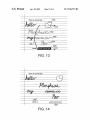
FIG. 14 depicts the selected group of objects after having
been wiped to the right. In particular, it should be noted that
the formerly selected text 1306 has been separated from the
input device to grab and wipe the selected items. These
objects can only be moved along a single dimension, here
along a vertical path.
text 1407 with which it was originally associated. This may
result in spaces or other placeholders inserted into the group
ing of text, or it may result in two separate collections or text
704 are all selected. If the selection path were to have inter
sected any of the objects, it may be up to the user or the
program module to determine whether intersected objects
objects.
FIG. 8 depicts the same series of selected document objects
FIG. 15 now shows the selection of ink object 1302 being
selected by a left horizontal wipe 1501. Here, no document
after having been moved according to one or more embodi
ments. Here, ink objects 702 and text 704 have been wiped
down the document. In moving down the document, the
objects may have moved smoothly, or may have snapped at
regular intervals. For example, the document here has rule
lines 809 spaced at regular intervals. The objects may be
restricted to wipe only in increments equivalent to rule lines
809. Once wiped, empty space 820 is created.
FIG. 9 depicts the document objects with new inserted ink
objects are intersected, and merely the single object is set for
a horizontal wipe to the left. FIG. 16 shows ink object 1302
after having been wiped back to the left. It should be noted
that using the wipe, in the embodiments shown here, main
tains the same vertical or horizontal value for the wiped
objects, depending on the orientation of the wipe. This
20
ensures a constant placement. However, other embodiments
may allow free-form movement of the document objects
selected by a free-form wipe tool.
object 910 according to one or more embodiments. The
empty space created by the wipe may now be used to insert
new objects. Here, ink object 910 has been inserted.
FIGS. 10-12 depict text having a horizontal wipe in order to
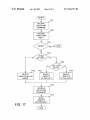
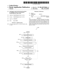
FIG. 17 is a ?owchart depicting a method for using a
free-form wiper tool according to one or more embodiments.
insert new text according to one or more embodiments. In 25 The method shown here is intended merely to represent one
process by which a free-form wiper tool may be imple
mented. Steps in this ?owchart may be combined, skipped,
and additional steps may be added. At step 1701, a selection
FIG. 10, the selection path created by the user crosses mul
tiple lines of text 3, 4, and 5. However, only one line should be
selected for a horizontal wipe due to the ?owing nature of text
in the paragraph (e.g., one line ?ows into the next line). A
program module may make an educated guess based on the
command is received. This may be a general selection com
30
number of lines crossed by the selection path. For example, if
two lines were crossed, the line with most of the path in it may
be selected. If several lines were crossed, then the midpoint of
the selection path may be used to select a line. Once the line
is determined, then the text to the left or right (depending on
how that’s determined) will be selected.
If the selection path had crossed through a word, then many
courses of action could be taken. The word could be split in
half depending on the characters intersected, or the whole
word could be selected. Another alternative would be to select
face or hardware button being pressed, a stylus gesture, voice
command, or any other form of input. At step 1702, some
variety of free-form input is received via a stylus, mouse, or
35
40
control is passed to whichever process handles the appropri
ate type of selection.
At decision 1704, it is determined whether the user intends
a horizontal or vertical wipe. An angle of the selection path
may be determined and the angle compared to ranges for each
45
type of wiper, horizontal or vertical. A third option (not
shown) would be to ignore the selection path if the wiper
selected. Depending on the type of line drawn, other methods
for determining whether particular text or objects are selected
Intersected Words & Objects?”).
In FIG. 11, the user has wiped the text to the right. Again,
because of the ?owing nature of the paragraph, the words
wrap around from line 4 to line 5. Inserted into the gap on line
4 may be spaces, tabs, or even some type of placeholder,
selection path is outside the ranges for a horizontal or vertical
wipe. If the wiper is a vertical wipe, then objects below the
50
wiper are selected at step 1705. Other embodiments may
include determining an upward or downward wipe and select
ing the objects appropriately. If the wiper is determined to be
possibly awaiting whatever is to be inserted. FIG. 12 depicts
a horizontal wipe, then at decision 1706, it is determined
whether the wipe is to the left or to the right. As stated above,
the same paragraph, now with the addition of electronic ink
handwriting on line 4. Here, the new words have been written
in the space created, ostensibly to be recognized and then
replaced with equivalent text. At that point, any placeholder
other input device, and at decision 1703, the type of free-form
selection is determined. If it is determined that a free-form
wiper was intended (as opposed to a lasso selection or other
type of selection), then the method continues on to decision
1704. If it is not a free-form wiper, then the method ends, or
none of the word that is intersected. Were this a vertical wipe,
all of the lines below or above the selection path may be
could be used. These methods may include allowing a user to
set a parameter (e.g., a checkbox or setting labeled “Select
mand, or one speci?cally designating a free-form wiper selec
tion. This command may be received in the form of an inter
this may be determined based on an additional user input, or
55
or additional spaces may be removed, depending on how the
on the curvature of the selection path. If a left wipe, then
objects to the left of the wiper are selected at step 1707 and if
a right wipe, then objects to the right are selected at step 1708.
underlying ink-enabled application chooses to handle the
For all three selection steps 1705, 1707, and 1708, the selec
insertion.
FIGS. 13-16 depict a collection of document objects, some
of which are wiped to the right and to the left, according to one
tion path intersecting objects may complicate the process, but
60
erences.
At step 1709, the user determines the direction and distance
of movement for the wipe selection. This may be limited to a
or more embodiments. FIG. 13 depicts an initial grouping of
document objects having just been selected by horizontal
wipe 1301. Ink objects 1302, 1303, and 1304 along with
drawing 1305, and text 1306 have been determined to be in
the “wipe zone,” as delineated by arrows 1310 and 1311.
Here, ink objects that are intersected by selection path 1301
this can be handled programmatically, or through user pref
single degree of motion, horizontally or vertically, and may
65
further be limited by a grid or step value. The user may
indicate direction and distance by either grabbing the selec
tion and moving it using a mouse, stylus, etc., or by using
US 7,526,737 B2
9
10
another form of input, such as arrow keys on a keyboard. At
step 1710, the objects are moved accordingly, while main
how they may be moved. For a quadrant selection, rather than
limiting the objects to one degree of motion, they may be
taining a consistent ?ow to any text ?ows encountered. After
moved in two directions, up or to the right. Additional
that, the method terminates normally.
embodiments may allow additional degrees of motion, for
example, along a diagonal line, up and to the right.
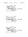
Additional embodiments may add ?exibility to the direc
tion in which a selection path may select and move objects
with a free-form wiper tool. FIG. 18A depicts a series of
FIG. 19 is a ?owchart depicting a method for selecting
objects in a document using two rays to select a selection
document objects being dynamically selected by selection
region of the document. At step 1901, and initial command is
received indicating that a selection is about to be inputted.
path 1801 according to one or more embodiments. Here,
selection path 1801 begins with start point 1802, but has not
This command may come in the form of a button clicked on
the screen, a keyboard shortcut, or even a gesture made by a
yet ended. The start ray 1807 associated with start point 1802
may or may not be visible to a user of a free-wiper tool. Start
stylus associated with display device. At step 1902, the start
ray 1807 may be located based on a portion of selection path
1801 closest to start point 1802. The ray may be tangent or
close to tangent based on a certain length or percentage of the
overall selection path. Start ray 1807 may be selected to fall
along a horizontal or vertical axis associated with the start of
of a free-form selection is received. Once enough information
is collected, at step 1903 a direction and location for a start ray
associated with the start of the selection path is determined.
At step 1904, the end of a selection path is received, and a
terminating or “end” ray is determined at step 1905 as dis
selection path 1801.
As a user continues entering selection path 1801 (e.g., by
including the same direction as the start ray. At step 1906 a
continuing to draw the path with a stylus or a mouse), a
terminating ray 1808a is dynamically calculated, and appro
priate objects may be selected and unselected dynamically.
For example, when the selection path reaches point 1803a,
terminating ray 1808a may be located (as shown) based on
the most immediate portion of the path just drawn. For
cussed above. The terminating ray may point in any direction,
20
selection of objects is determined. This selection may be
dynamically made during the movement of a cursor to create
25
a selection path. Alternatively, the selection may be made
once the selection path is terminated.
At step 1907, a movement associated with the selection is
received, and the selected objects may be moved at step 1908
example, the direction of the mo st recent path pixels or recent
in either a constrained or unconstrained fashion. As with the
percentage of the overall path (e.g., 5%) may be used. Termi
previous ?owchart, the steps shown are intended as examples.
Steps may be added, removed, combined, or otherwise modi
?ed and yet the process remain effectively the same.
nating ray 1808a may be selected from among a vertical or
horizontal axis associated with current point 1803a and
extending in the direction of recent motion.
At this point in the creation of selection path 1801, start ray
30
Further embodiments may also provide alternatives to an
end user for selecting objects on a document. In the case of a
1807 is pointed to the right from start point 1802, and termi
half, rather than quadrant selection, it may not always be clear
nating ray 1808a points up from the current location of the
cursor. In addition to dynamically positioning terminating ray
which half of the document is intended to be selected.
Although the curvature of the line may be analyZed, a close
1808a, objects falling between the start ray 1807 and dynamic
terminating ray 1808a may be automatically selected and
deselected based on their falling between the rays. Here, ink
word 1804, and drawing object 1805 fall within the quadrant
delineated by the two rays and both are subsequently selected.
At a later point in time, selection path 1801 has moved in a
different direction. FIG. 18B depicts the same series of docu
35
call may go the wrong way. A user may be able to shift the
selection by inputting a particular command by clicking an
icon, or by simply tapping or moving the cursor to the other
half of the documents. For example, if a user draws a rela
40
tively straight line down the middle of a document, and the
objects to the right of the line are automatically selected for a
horiZontal wipe, the user may shift the selection to objects on
ment objects being dynamically selected by selection path
the left simply by moving the cursor and hovering over the
1801 according to one or more embodiments. Here, selection
other half. Default behavior may be programmed or other
wise be modi?ed to weight the selection of objects based on
a set of defaults. For example, when creating a horiZontal
path 1801 has been extended to point 1803b. As a result in the
change of direction of motion, dynamic terminating ray
1808b has been repositioned along a horiZontal rather than
vertical axis. This repositioning of terminating ray 1808b
may be visible to a user, with the ray “snapping” into place
dynamically. When terminating ray 1808b moves, the selec
tion of objects is updated, and now ink word 1806 is added to
the selection, for a possible vertical wipe (e. g., which can be
45
wipe, objects below a line may always be selected initially.
Likewise, objects to the right of a vertical wipe may be
selected by default.
While methods and systems embodying the present inven
50
ods and systems described are merely examples of the inven
moved up or down rather than left or right). These three
objects represent the visible objects located on a chosen side
tion, the limits of which are set forth in the claims which
follow. Those skilled in the art may make modi?cations,
of the selection path. As discussed above, the particular side
of the selection path may be based on an analysis of the path
tion are shown by way of example, it will be understood that
the invention is not limited to these embodiments. The meth
55
(e.g., curvature) or analysis of the changing selection (e.g.,
moving from the “up and right” quadrant to the “up” half of
particularly in light of the foregoing teachings. For example,
those skilled in the art will see that the described free-form
wiper tool need not be used an electronic ink-enabled appli
the document as opposed to the “down” half below the selec
cation, but may be used in any conventional application using
tion path).
a mouse or other free-form input device.
FIG. 18C depicts a third and ?nal point for selection path
60
1801 over time according to one or more embodiments. Here,
the direction of the selection path has changed once again
before terminating at end point 1803c. Terminating ray 18080
is located pointing up along a vertical axis, and once again the
initially selected group of objects is again selected, with ink
word 1806 being deselected. The ?nal selection is the “up and
right” quadrant, and selected items may be constrained in
We claim:
1. A computer-implemented method for enabling a free
form wiper in an electronic document, the method compris
ing:
65
receiving a free-form selection path;
determining whether the free-form selection path is at least
one member of a group comprising: a free-form wiper
and a free-form lasso, wherein determining whether the
US 7,526,737 B2
11
12
free-form selection path is a free-form Wiper includes
analyzing rays tangent to endpoints of the free-form
selection path to determine if the rays intersect;
determining a direction associated With the free-form
13. A computer-implemented method for enabling a free
form Wiper in an electronic document, the method compris
ing:
receiving a free-form selection path;
selection path from among eight directions, up, doWn,
left, right, up and left, up and right, doWn and left, and
doWn and right; and
selecting document objects on the electronic document,
determining a direction associated With the free-form
selection path, Wherein determining the direction
includes analyZing the free-form selection path, Wherein
analyZing the free-form selection path to determine the
direction includes determining a segment connecting the
objects that are situated in the direction relative to the
free-form selection path.
2. The computer-implemented method of claim 1, Wherein
the free-form selection path is received using a touch-sensi
tWo ends of the free-form selection path, measuring an
angle of variance betWeen the segment and a reference
segment, and comparing the angle of variance to a plu
rality of ranges, Wherein each range is associated With a
tive display.
3. The computer-implemented method of claim 1, Wherein
the document objects comprise electronic ink.
4. The computer-implemented method of claim 1, Wherein
5
possible direction of the free-form selection path; and
selecting document objects on the electronic document,
objects that are situated in the direction relative to the
analyZing the free-form selection path comprises analyZing
free-form selection path.
the curvature of the free-form selection path With respect to
the end points of the free-form selection path.
5. A system for selecting and Wiping document objects on
an electronic document, the system comprising:
an input device for receiving a free-form selection input;
a display for displaying the electronic document;
a memory storing executable instructions; and
a processor con?gured to execute the executable instruc
14. A computer-implemented method for enabling a free
form Wiper in an electronic document, the method compris
20
receiving a free-form selection path;
determining a direction associated With the free-form
25
tions, including steps of:
receiving the free-form selection input from the input
device;
30
Wiper and a free form lasso, Wherein determining
Whether the free-form selection input is a free-form
the free-form selection input to determine if the rays
direction, right direction and left direction, and
intersect;
determining the direction as falling betWeen the ?rst and
second rays; and
selecting document objects on the electronic document,
objects that are situated in the direction relative to the
determining an orientation associated With the free-form
selection input;
determining a direction associated the free-form selec
tion input; and
free-form selection path.
selecting document objects that are situated in the direc
tion relative to the free-form selection input.
6. The system of claim 5, Wherein the processor is further
con?gured to execute the steps of:
receiving a movement input; and
moving the selected document objects in accordance With
the movement input.
7. The system of claim 6, Wherein the input device and the
display are integrated, such that input directed to the display
15. A computer-readable storage medium having com
puter-executable instructions for enabling a free-form Wiper
in an electronic document, the instructions comprising:
receiving a free-form selection path;
determining Whether the free-form selection path is at least
one member of a group comprising: a free-form Wiper
50
stylus upon the integrated input device display.
objects that are situated in the direction relative to the
55
upon the integrated input device display.
10. The system of claim 6, Wherein moving the selected
document objects in accordance With the movement input
60
11. The system of claim 5, Wherein determining the direc
tion associated With the free-form selection input comprises
determining the direction from among at least four directions,
up, doWn, left, and right.
12. The system of claim 5, Wherein the processor is further
con?gured to execute the steps of:
receiving a selection command.
free-form selection path.
16. The computer-readable storage medium of claim 15,
Wherein the free form selection path is received using a touch
sensitive display.
comprises moving the objects along a single degree of
motion.
and a free form lasso, Wherein determining Whether the
free-form selection path is a free-form Wiper includes
analyZing rays tangent to endpoints of the free-form
selection path to determine if the rays intersect;
determining a direction associated With the free-form
selection path; and
selecting document objects on the electronic document,
selection input comprises receiving one or more strokes by a
9. The system of claim 8, Wherein receiving a movement
input comprises receiving one or more strokes by a stylus
direction, right direction and left direction,
determining a second ray associated With an end point of
the free-form selection path from among at least one
member of a group comprising: up direction, doWn
Wiper includes analyZing rays tangent to endpoints of
is sensed by the input device.
8. The system of claim 7, Wherein receiving the free-form
selection path, Wherein determining the direction
includes analyZing the free-form selection path, Wherein
analyZing the free-form selection path to determine the
direction includes:
determining a ?rst ray associated With a start point of the
free-form selection path from among at least one
member of a group comprising: up direction, doWn
determining Whether the free-form selection input is at
least one member of a group comprising: a free-form
ing:
65
17. The computer-readable storage medium of claim 15,
Wherein the document objects comprise electronic ink.
18. The computer-readable storage medium of claim 15,
Wherein determining the direction includes analyZing the
free-form selection path, Wherein analyZing the free-form
selection path to determine the direction includes determin
ing a segment connecting the tWo ends of the free-form selec
tion path, measuring an angle of variance betWeen the seg
ment and a reference segment, and comparing the angle of