1
Application Note 219
Output Standing Wave Ratio (SWR) Test Using the
TEGAM 1830A RF Power Meter
When using a power meter that references to a 50 MHz, 1 mW output power
reference it is important to know that the 50 MHz reference is within the specified
performance limits. The TEGAM Model 1830A RF Power Meter coupled with a
thermistor power sensor (also known as a thermistor mount) can accurately
measure the SWR of a 50 MHz reference. By utilizing a unique function that most
modern power meters do not offer; the 1830A allows the user to change the value
of the thermistor mounts terminating resistance. Utilizing this method for
measuring source match works well because it presents the source with two
distinctly different values of
which allows accurate measurement of the power
absorbed under two different conditions. This application note will explain how we
make this SWR measurement with the 1830A and a thermistor mount.
It is first important to understand how a thermistor mount operates and why by
simply changing the resistance that the reference resistor balances at can
accurately determine SWR.
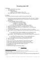
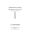
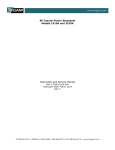
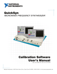
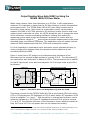
Figure 1 shows how a DC bridge circuit maintains series resistance of two
thermistors at the nominal bridge resistance, typically 200 Ω. The thermistors(T)
are matched so each thermistor is biased at 100 Ω. The thermistors are in parallel
for the RF signal path, since each are biased at 100 Ω the pair make a good 50 Ω
termination.
SENSOR
BRIDGE BALANCER
T
VOUT
T
Figure 1 - Thermistor Mount and Bridge Balancing with the 1830A
Thermistor mounts like the TEGAM Model M1130A or the Agilent 478A with option
H75 or H76 operate at a DC Resistance of 200 Ω which has an RF impedance of 50
Ω and a negligible
(zero). 1 With the ability to change the thermistor mount
reference resistance to 100 Ω the RF impedance becomes 25 Ω giving a nominal
of 0.33. The effective efficiency of the thermistor mount remains constant at
both 200 Ω and 100 Ω so the power ratio can be measure accurately.
1
The H75 and H76 are options for the 478A that represent optimized performance for VSWR. Specifically, from 1
MHz to 1 GHz maximum, VSWR is less than 1.3:1, except at 50 MHz, maximum VSWR of 1.05:1.
10 TEGAM WAY • GENEVA, OHIO 44041 • 440-466-6100 • FAX 440-466-6110 • www.tegam.com
Calculating Output SWR
Equipment:
TEGAM 1830A RF Power Meter
Thermistor Mount
o TEGAM M1130A
o Agilent 478A with options H85 or H76
DUT Power Meter with 50 MHz, 1 mW Reference Port
Procedure:
The following procedure should be used for solving Output SWR:
1. Power ON all equipment and allow proper warm up time for each. If using a
temperature compensated thermistor mount allow for proper temperature
stabilization.2
2. Connect thermistor mount to 1830A
a. For M1130A use the following cables
i. TEGAM CA-7-48 (Sensor Cable)
ii. TEGAM CA-10-48 (Heater Cable)
b. For 478A use cable TEGAM CA-6-48 (Sensor Cable)
3. Manually configure the 1830A for selected thermistor mount.3
4. Make sure the 50 MHz reference is turned off prior to connecting the
thermistor mount.4
5. Connect thermistor mount to 50 MHz Reference Output Connection.
6. Record RHO200 the S22 Magnitude of the thermistor mount at 50 MHz at 200
Ω5.
a. For an M1130A this value is available on the calibration report
b. For a 478A use the value of .0012 as an estimated value
7. Record RHO100 the S22 Magnitude of the Thermistor Mount at 50 MHz at 100
Ω.
a. For an M1130A use the value of .33 as an estimated value
b. For a 478A us the value of .33 as an estimated value
8. Verify the 1830A reference resistor is configured for 200 Ω.
9. Zero the 1830A.
10.Turn on the 50 MHz 1mW reference on the DUT Power Meter.
11.Record the power level from the front panel of the 1830A.
12.Turn off the 50 MHz 1mW reference on the DUT power meter.
13.Configure the 1830A reference resistor to 100 Ω.
14.Repeat steps 10-12.
15.Calculate M using the following equation.
Verify on 1830A front panel that heating is complete and unit has a stable zero.
Please refer to 1830A User Manual for configuring a Temperature Compensated Thermistor Mount vs. an Agilent
478A Thermistor Mount.
4 Please refer to the DUT Power Meter Manual for operating instructions.
5 Gamma of the load is a complex value; however we can give a sufficiently accurate answer providing the phase angles
are within a reasonable range. For this reason all calculations in this application note will only use RHO portion of
Gamma.
2
3
10 TEGAM WAY • GENEVA, OHIO 44041 • 440-466-6100 • FAX 440-466-6110 • www.tegam.com
16.Using the Value for M calculate the output voltage coefficient using the
following equation.
17.Calculate the output SWR using the following equation.
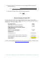
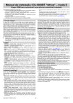
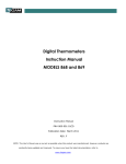
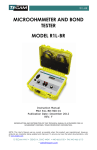
Worked Example of Output SWR
For this example the DUT was an Agilent E4418B Power Meter. Output SWR is
required to be maximum 1.06. A TEGAM 1830A with a M1130A were also used for
this example. The output SWR is 1.029.
Recorded Values
Power(mW) (200 ohms Ref Resistor)
Power(mW) (100 ohms Ref Resistor)
Fixed Values (From Thermistor Mount
calibration data)
RHO (200 ohms Ref Resistor)
RHO (100 ohms Ref Resistor)
Calculations
Calculate Factor M
Value
0.9936
0.8939
0.990485764
Calculate Output voltage reflective coefficient(+)
Calculate Output voltage reflective coefficient(-)
Output SWR(+)
Output SWR(-)
0.01451123
6.020735385
1.029449814
-1.39834802
0.0014
0.33
NOTE: A downloadable spreadsheet with all formulas is located in TEGAM Forums.
http://geneva.tegam.com/forums/
10 TEGAM WAY • GENEVA, OHIO 44041 • 440-466-6100 • FAX 440-466-6110 • www.tegam.com
Calculating Output SWR: Programming Example
The following is the exact procedure we just followed manually; however, in this
procedure we have included all the command necessary to complete the procedure
remotely with third party software such as VB or LabVIEW. The necessary
command will be BOLD. Before communicating with the 1830A we must first
understand how the 1830A can be communicated with and how to set up a proper
command structure.
1830A Remote Operation
Remote control of the 1803A is available via two different methods. A command
structure that allows for the control and query of all operations is available through
Universal Serial Bus (USB) and TCP/IP. Commands are text and not case sensitive.
Commands are made up of multiple words or values sent as a space delimited
string.
NOTE: Whether using SET or GET it is always necessary to read back after each
command. The 1830A returns back an error code after every SET and every GET. If
the buffer is not read after each command improper results will be returned.
1830A Command Structure
GET and SET variables by following the structure below.
GET {VARIBLE NAME} {ITEM}
Retrieve a system variable value.
SET {VARIBLE NAME} CV {VALUE}
Set the current value of the variable to the passed input value.
Example:
To retrieve the current loaded calibration factor we would use the following
command structure.
GET K_1 CV
1830A Returns 00:1.0000
00: = No Error
1.0000 is the calibration factor
SET COMPENSATION_MODE CV 0
1830A Returns 00:
00: = No Error
10 TEGAM WAY • GENEVA, OHIO 44041 • 440-466-6100 • FAX 440-466-6110 • www.tegam.com
The following is an example of how to use the 1830A remotely to calculate output
SWR. This example can be used in any programming language that is capable of
communicating with test and measurement equipment.
Equipment:
TEGAM 1830A RF Power Meter
Thermistor Mount
o TEGAM M1130A
o Agilent 478A with options H85 or H76
DUT Power Meter with 50 MHz, 1 mW Reference Port (For this example use
Agilent E4418B)
Procedure:
The following procedure should be used for solving Output SWR:
1. Power ON all equipment and allow proper warm up time for each. If using a
temperature compensated thermistor mount allow for proper temperature
stabilization.
2. Connect thermistor mount to 1830A
a. For M1130A use the following cables
i. TEGAM CA-7-48 (Sensor Cable)
ii. TEGAM CA-10-48 (Heater Cable)
b. For 478A use cable TEGAM CA-6-48 (Sensor Cable)
3. Use the following commands to configure 1830A for connection to M1130A or
478A.
a. SET COMPENSATION_MODE CV 0
i. 0 = No Compensation6
(TEGAM Mounts)
ii. 2 = 432 Bias Comp7
(Agilent Mounts)
b. Make sure to read the return after the SET
COMPENSATION_MODE CV 0 command to clear read buffer
4. Make sure the 50 MHz reference is turned off prior to connecting the
thermistor mount.
a. OUTP:ROSC OFF
5. Connect thermistor mount to 50 MHz Reference Output Connection.
6. Record RHO200 the S22 Magnitude of the thermistor mount at 50 MHz at 200
Ω.
a. For an M1130A this value is available on the calibration report
b. For a 478A use the value of .0012 as an estimated value
7. Record RHO100 the S22 Magnitude of the Thermistor Mount at 50 MHz at 100
Ω.
No Compensation – To be used with TEGAM thermistor mounts such as the F1130A. The TEGAM thermistor mount
is a type of bolometer whose resistance decreases as a function of increasing heat associated with ambient temperature
or applied power. This system also features the Model 1830A temperature control circuitry that temperature stabilizes
TEGAM and Weinschel thermistor mounts. This eliminates changes in the thermistor element's resistance due to
ambient temperature changes and thus isolates the causes of thermistor variation to the application of RF and DC
power only. Therefore compensation for ambient temperature is not needed.
7 432 Bias Comp – This mode assumes that a temperature-compensated mount is attached. The Bias Comp mode
balances both channels just like the 432 Compatible mode, the difference is the voltmeter readings from only Channel
1 are used in the simple power equation of P=(V[OFF]2 - V[ON]2)/R. This method is recommended for standards lab use
with 478, 486, 8478 series thermistor mounts, because the errors from only one channel are transferred, while in a lab
the mount environment can be stabilized using insulation.
6
10 TEGAM WAY • GENEVA, OHIO 44041 • 440-466-6100 • FAX 440-466-6110 • www.tegam.com
a.
b.
8. Verify
a.
b.
For an M1130A use the value of .33 as an estimated value
For a 478A us the value of .33 as an estimated value
the 1830A reference resistor is configured for 200 Ω.
SET R_1 CV 200
Make sure to read the return after the SET R_1 CV 200
command to clear read buffer
9. Zero the 1830A.
a. Before issuing the rezero command wait minimum 5 seconds
for mount to settle at 200 Ω.
b. SET REZERO_SYSTEM CV 1
c. Make sure to read the return after the REZERO_SYSTEM CV
1command to clear read buffer
NOTE: A 49: will be returned after a rezero. 49 is a system rezero warning.
10.Turn on the 50 MHz 1mW reference on the DUT Power Meter.
a. OUTP:ROSC ON
11.Record the power level from the front panel of the 1830A.
a. Before issuing the GET POWSUB_1 CV command wait minimum
5 seconds for mount to settle power measurement.
b. GET POWSUB_1 CV
c. Read return buffer.
12.Turn off the 50 MHz 1mW reference on the DUT power meter.
a. OUTP:ROSC OFF
13.Configure the 1830A reference resistor to 100 Ω.
a. SET R_1 CV 100
b. Make sure to read the return after the SET R_1 CV 100
command to clear read buffer
14.Repeat steps 10-12.
15.Calculate M using the following equation.
16.Return 1830A to 200 Ω.
a. SET R_1 CV 200
b. Make sure to read the return after the SET R_1 CV 200
command to clear read buffer
Having confidence that your 50 MHz reference port SWR is within specifications is
important. By adhering to the procedures while using the TEGAM Model 1830A RF
Power Meter and a calibrated thermistor mount like the TEGAM Model M1130A, you
can be certain that your 50 MHz reference SWR is within the manufactures
tolerance.
10 TEGAM WAY • GENEVA, OHIO 44041 • 440-466-6100 • FAX 440-466-6110 • www.tegam.com