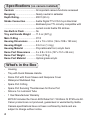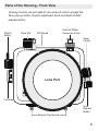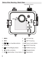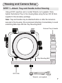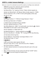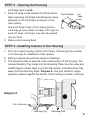
1
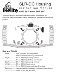
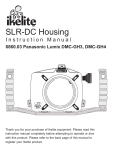
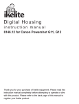
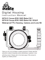
D igital Hous i n g
Instruction Manual
6970.01 Canon EOS 100D Rebel SL1
6970.02 Canon EOS 100D Rebel SL1 DSLR
Waterproof TTL Housing, Camera, and Lens Kit
Thank you for your purchase of Ikelite equipment. Please read this
instruction manual completely before attempting to operate or dive
with this product. Please refer to the back page of this manual to
register your Ikelite product.
Table of Contents
Preparation ..................................................................P. 3
Specifications ..............................................................P. 4
What’s in the Box ........................................................P. 4
Parts of the Housing - Front View ..................................P. 5
Parts of the Housing - Back View ..................................P. 6
Housing and Camera Setup ........................................P. 7
STEP 1 - Attach Tray and Handle to the Housing ..........P. 8
STEP 2 - Initial Camera Settings ....................................P. 8
STEP 3 - Opening the Housing ......................................P. 9
STEP 4 - Installing Camera in the Housing ....................P. 9, 10
STEP 5 - Attach the Hotshoe ..........................................P. 11
STEP 6 - Closing the Housing ........................................P. 11
STEP 7 - Final Check......................................................P. 12
Usage ............................................................................P. 12
Turn Camera On..............................................................P. 12
Removing the Camera from the Housing........................P. 13
Strobe Use and Compatibility ....................................P. 14
Strobe Compatibility ........................................................P. 14
Ikelite Housing Conversion Circuitry ..............................P. 14
Attaching a Sync Cord to the Housing ............................P. 14, 15
Housing Lens/Port Options ............................................P. 16
Removing the Port ..........................................................P. 17
Installing the Port ............................................................P. 18, 19
Attaching an Ikelite Strobe Arm to the Housing Handle..P. 20
2
Table of Contents - continued
Entering the Water ..........................................................P. 21
Spare Parts ..................................................................P. 21
Recommended Accessories ......................................P. 21
Maintenance ................................................................P. 22-25
Photo Tips ..................................................................P. 26
Troubleshooting
........................................................P. 27-29
Customer Support ......................................................P. 30
Limited Warranty ........................................................P. 30
Returning Products for Service ................................P. 31
Product Registration ..................................................Back Page
Preparation
This product has been water pressure tested at the factory and is depth
rated to 200ft (60m). Thoroughly inspect and immerse the empty
housing completely in water before installing a camera. If any fogging
occurs or droplets of water enter the housing, do not install a camera.
Clean the main housing o-ring and retest to make sure that it is
watertight. Refer to the Troubleshooting section, page 27.
Please read your camera manual thoroughly to have a full
understanding of each camera function.
If you are new to underwater photography, be sure to read the Photo
Tips section, page 26.
3
Specifications
(no camera installed)
Controls ................................All important camera functions accessed
Buoyancy ..............................Nearly neutral in saltwater
Depth Rating..........................200 ft (60 m)
Strobe Connection ................Ikelite Digital TTL ICS-5 5-pin Electrical
................................................Bulkhead plus TTL circuitry compatible with
................................................current model Ikelite DS strobes
Use Built-in Flash..................No
Tray and Handle Weight ......11.5 oz (327 g)
Main O-Ring ..........................0110
Housing Dimensions ............6.4 x 7.5 x 5.9 in (164 x 189 x 150 mm)
Housing Weight ....................3 lb 3 oz (1.4 kg)
Housing Material ..................Polycarbonate front, acrylic back
Dome Port Dimensions ........5 x 5.9 x 3.3 in (127 x 151 x 85 mm)
Dome Port Weight ................13 oz (376 g)
Dome Port Material ..............Optical grade acrylic
-
-
4
What’s in the Box
Housing
Tray with Quick Release Handle
Dome Port with Zoom Sleeve and Neoprene Cover
Waterproof Bulkhead Cap
Spare Port O-Ring
Spare Port Securing Thumbscrews for Dome Port
Silicone 1cc Lubricant Tube
1 Year Manufacturer Warranty
6970.02 includes the Canon EOS Rebel SL1 18-55mm IS STM Lens Kit.
Canon products are not produced, guaranteed or warrantied by Ikelite.
Camera specifications have not been confirmed by Ikelite and are
subject to change without notice.
Parts of the Housing - Front View
Housing controls are provided for all camera functions except the
flash pop-up button, dioptric adjustment knob and depth-of-field
preview button.
Shutter
Button
Main Dial
ISO Speed
External Strobe
Connector & Cap
Zoom
Control
Lens Port
Lid Snap
External Tray Mounts
Lens
Release
Button
5
Parts of the Housing - Back View
Power/Movie Switch
4
INFO
MENU
3
1 2
Av
7
5
6
8
9 10 11
12
13 14
1. MENU
2. INFO
3.
8.
Live View/Movie Button
4. Mode Dial
5.
6.
7. Av
6
AF Point/Magnify Button
AE/FE Lock Button
9.
UP Cross Key
LEFT Cross Key
10. SET Quick Control Button
11.
RIGHT Cross Key
13.
Playback Button
12.
Aperture/Exp. Comp. Button 14.
DOWN Cross Key
Erase Button
Housing and Camera Setup
STEP 1 - Attach Tray and Handle to the Housing
Using a 9/16” open/box end or socket Wrench (not supplied), firmly
tighten the External Tray to the Housing Base using the two 3/8-16 Nuts
supplied in the accessory package.
Note: Tray and Handle may be attached before or after the camera is
secured in the Housing. We recommend attaching it immediately to avoid
scratching table tops with the Tray Mounting Bolts.
External Tray & Handle
Tray Mounting Bolt
3/8-16 Nut
Wrench - not supplied
7
STEP 2 - Initial Camera Settings
Setup your camera for underwater use and then adjust your settings once underwater.
-
-
-
*
*
*
8
REMOVE eyecup from camera’s optical viewfinder.
Insert a fully charged camera battery.
Set Mode Dial to “Av” Aperture Priority. If faster shutter speeds are
desired, set Mode Dial to “M” Manual Mode; shutter speed to 1/125th
second; aperture to F8, or F22 for macro photography (close-ups).
Set ISO to “200.”
IN
MENU:
Set Image Quality to “L” 18M and Image Review to “8 sec.”
Set Red-eye Reduction to “Disable.”
In Flash Control set Flash Firing to “Enable.”
Set Auto Lighting Optimizer to “OFF.”
Set White Balance to “AWB.” For best results, use manual
Custom
White Balance and reset for each working depth.
Set AF Operation to “ONE SHOT AF.”
Set Metering Mode to “ Center-weighted average
.”
Set Live View Shoot. to “Enable.” TIP: Turning off Live View Shooting
will decrease shutter lag time.
Set AF Method to “Quick Mode” and Aspect Ratio to “4:3.”
Set Metering Timer to “4 sec.”
IN
MENU:
Insert and format a high capacity SD card.
Set Auto Power Off to “4 min” and LCD Auto Off to “Disable.”
Set Touch Control to “Disable.”
All other camera functions not mentioned should be set to the user
preference.
Many camera functions can be quickly set with the “Q-SET” button.
Flash
can be set through the camera menu.
STEP 3 - Opening the Housing
Lid Snaps have a Lock.
1. Push Lid Snap Locks forward and lift as shown.
Open opposing Lid Snaps simultaneously. Keep
pressure on the Lid Snaps so they do not fly
open quickly.
Some Lid Snaps have a lot of spring tension
once they go over center, so keep a firm grip on
each Lid Snap. Lid Snaps may also be opened
one at a time.
2. Remove the Housing Back.
Push Forward
Lid
Snap
Lock
Lift
STEP 4 - Installing Camera in the Housing
1. Pull out on each housing control until it stops. This will get the controls
out of the way for installation of the camera.
2. Remove camera lanyard from camera if attached.
3. The Mounting Plate is secured to the inside bottom of the housing. The
camera Mounting Tray slides into the Mounting Plate. Use the index and
middle fingers of each hand to pull the Tab section of the Mounting Tray
away from the Mounting Plate, Diagram A. Use your thumbs to apply
opposite pressure against the bottom of the housing to assist in removal.
Diagram A
Pull to Remove
Mounting Tray
Mounting Plate
9
STEP 4 - Installing Camera in the Housing - continued
5. Using a coin or flathead screwdriver
(preferred), secure the camera
Mounting Tray to the camera tripod
mount, Diagram B. The Mounting
Tray only attaches one way with the
Tab to the back of the camera.
An additional Tray hole allows
attachment to a land tripod stand.
Diagram B
Tab
Mounting Tray
6. Gently slide the camera with Mounting Tray back into the Mounting
Plate, Diagram C. Using your thumbs, push against the Mounting Tray
Tab until the Tray stops sliding forward into the Mounting Plate. Give the
Tray an extra push to make sure it is properly seated all the way forward
in the Mounting Plate, Diagram D.
Diagram C
Tab
Mounting Tray
Diagram D
10
Push Camera and
Mounting Tray all
the way forward into
the Mounting Plate
Mounting Plate
STEP 5 - Attach the Hotshoe
Slide Hotshoe into the top
camera mount until it stops.
Hotshoe must be all the way
forward in the camera mount
to assure a good electrical
connection with a strobe.
Make sure hotshoe cord does
not interfere with the back
when closing housing.
Hotshoe
STEP 6 - Closing the Housing
1. Place housing face down in your
Lid Hook
lap or on a flat surface. Check to
Housing Back
see that there is an o-ring on the
housing back, and that it is clean
and in its proper location.
2. Guide the back onto the housing
Even gap on
front. Make sure the hotshoe wire all four sides
is out of the way. Once the back
O-ring
Lid
is properly installed, the o-ring
Snap
should touch the housing all the
way around. There should be an even gap on each side of the housing
between the housing and the back.
3. Lift the lid snaps so they are extended and place each lid snap into the
corresponding hook on the housing back.
4. To close the housing, push down on the opposing lid snaps
simultaneously until they snap into place. Be sure they are down far
enough to engage the lock - Page 9. The o-ring seal should now appear
as a solid black line from the back of the housing.
11
STEP 7 - Final Check
The clear housing permits instant visual inspection of the camera and
sealing surfaces as well as complete monitoring of controls and camera
LCD screens. This housing has been factory water pressure tested to
200 ft (60 m).
Once the housing is closed, recheck the o-ring seal. Double check the
gap between the housing back and the housing. It should be even all the
way around the housing.
Look through the clear plastic back at the o-ring. You should see a
darkened area or solid black line where the o-ring is compressed against
the housing back. If you do not see an even black compression seal all
the way around the back, open the lid snaps, reseat the housing back and
close the lid snaps. Visually check the seal again.
The Housing Dome Port is attached from the factory and does not need to
be removed unless you are installing optional 9304.43 Flat Port for the
Canon EF-S 60mm Macro lens. The Dome Port Shade Extensions should
be at the 6 and 12 o’clock position. If they are not, gently rotate the port
on its base to align properly. Check the Port Thumb Screws for tightness
using your thumb and index finger. The Thumb Screws should be
hand-tightened only. If a Thumb Screw becomes missing or lost, there are
spares included with the Housing.
Usage
Turn the camera on and operate each of the housing controls to get a
feel for using the camera in the housing. Take a few test shots on land.
12
This housing is designed to be used specifically with available light or
connected to an external strobe through the housing bulkhead ONLY.
There is no room for the pop-up flash to operate, therefore, fiber optic
cords cannot be used. If you are using an external strobe, see Page 14.
Removing the Camera from the Housing
1.
2.
3.
4.
Thoroughly dry Housing.
Remove the Housing Back, Step 3, Page 9.
Gently remove the Hotshoe from the Camera Mount.
Place your index fingers over the top of the camera on opposite sides of
the flash, Diagram E. Pull the camera backward and remove from the
housing.
If you are finished using the housing, remove the Mounting Tray from
the camera bottom and slide it back into the Housing Mounting Plate,
before replacing the Housing Back.
Note: The Mounting Tray does NOT need to be removed when
changing a camera battery or memory card.
Diagram E
13
Strobe Use and Compatibility
-
Strobe Compatibility
AF35 ........................no
DS50........................yes, above serial number 70,000
DS51........................yes
DS125......................yes, above serial number 5000
DS160, DS161 ........yes
DS200......................yes
Manta ......................no, except as secondary strobe triggered off primary
Non-Ikelite ..............yes, manual flash exposure only
Ikelite Housing Conversion Circuitry
This small compact digital SLR housing has Ikelite designed and
patented Conversion Circuitry built right in. The Conversion Circuitry
provides real Canon eTTL flash exposure when used with Ikelite DS
series strobes. Once a DS series strobe is attached to the camera
housing, the conversion circuitry is automatically powered after the
strobe is turned on. Once attached, turn the strobe on first before turning
on the camera. The circuitry cannot be powered up or used by
non-Ikelite strobes.
If Manual flash is desired, press the
button twice within 2 seconds
and then use manual power settings on the strobe. To go back to TTL,
turn the strobe off and back on; return strobe power switch to TTL.
Attaching a Sync Cord to the Housing - Diagram F, Page 15
The Housing Bulkhead is designed to accept sync cords with Ikelite
ICS-5 connector fittings.
1. Lightly lubricate the Sync Cord O-ring. Use ONLY Ikelite lubricant
(supplied with housing).
2. Remove Bulkhead Cap from Housing Bulkhead.
14
Attaching a Sync Cord to the Housing - continued
3. Line up the Sync Cord Pins with the corresponding Bulkhead
Receptacles. Gently insert Sync Cord into Bulkhead. DO NOT force this
installation. If the Sync Cord does not seat properly inside the Bulkhead,
then the Pins and Receptacles are improperly aligned (repeat Step 3).
4. Tighten the Knurled Nut snugly using your Index finer and thumb. DO
NOT use pliers or other tools to tighten the Knurled Nut.
-
Always remove the Sync Cord from your Housing when not in use and
replace the Bulkhead Cap.
Diagram F
Ikelite TTL
Sync Cord
Knurled Nut
Sync Cord O-ring
Bulkhead
Cap
Sync Cord Pin
Housing
Bulkhead
15
Housing Lens/Port Options
9304.52 Dome Port (included with housing)
The housing comes standard with an optical grade acrylic dome port
with zoom ring. This port provides sharp images and zoom capabilities
with both the Canon EF-S 18-55mm STM kit lens, plus the popular
Tokina 10-17mm lens. Minimal vignetting (dark shadows in the corners
of the image) will be present in the 10-12mm range when used with the
Tokina lens. A special zoom gear system allows the camera with lens
attached, to be installed from the back of the housing without requiring
removal of the dome port. No other lenses or ports are compatible with
this compact housing with the exception of the 9304.53 optional Flat
Port and Canon EF-S 60mm Macro lens.
It is not necessary to remove the Dome Port unless you are installing
the optional Flat Port or replacing the Dome Port.
9304.53 Flat Port (optional)
The optional Flat Port allows use of the 60mm Macro lens in auto-focus
mode and features 67mm front threads for the optional attachment of
macro converter wet lenses.
This housing is NOT compatible with Fixed Lens Ports or Modular Lens
Ports from our standard DSLR Lens Port Systems.
16
Removing the Port
The Dome Port never needs to be removed unless replacing the Gear
Sleeve or installing the optional Flat Port.
No tools are needed to remove the Dome Port and attach the optional
Flat Port for the Canon EF-S 60mm Macro lens, Diagram G.
1. Three thumb screws secure the Port on the Base. Turn each thumb
screw counterclockwise so at least 3 to 4 threads are showing.
2. Gently lift the Dome Port off the Port Base, Diagram H, Page 19. If the
Port seems stuck, loosen the thumb screws another turn until the Port
can be removed.
Caution:
DO NOT leave the Port off the Port Base for extended
periods of time. This can result in debris being attracted to the port base
o-ring resulting in a bad seal.
Diagram G
Approximately 3/32” gap
will be present between
the Housing Front and
bottom of Port when
the Dome or Flat Port is
properly installed.
Tighten
Loosen
17
Installing the Port - Diagram H, Page 19
1. To reinstall, first check to see that there is a thin film of lubricant on the
port base o-ring. The o-ring should appear slick. If necessary, relubricate
with the supplied Ikelite lubricant. Do not use excessive lubricant which
can attract hair or other debris. Use ONLY Ikelite lubricant.
2. Make sure the o-ring is free of hair or other debris.
3. The gear sleeve should be in its proper position inside the Port Base
with the teeth facing up. REMOVE the gear sleeve when using the Flat
Port.
4. Slide the Port over the Port Base until it STOPS. When properly
installed, there should only be an approximate 3/32” gap between the
bottom of the Port and the front of the housing, Diagram G, Page 17.
5. Rotate Port so the Shade Extensions are at the 12 and 6 o’clock
position, and the Zoom Knob is opposite the Handle.
6. Snugly tighten the 3 thumb screws into the Port Base. DO NOT
overtighten. No Thumb Screw threads will be visible once the Port is
properly secured.
7. Check zoom function; Not applicable when using the Flat Port.
*
Use the same removal/installation procedure for optional 9304.53 Flat
Port. The gear sleeve must be REMOVED before using the Flat Port.
*
We recommend placing the closed housing in a pool or bathtub to
assure proper installation and watertightness before installing your
camera.
18
Installing the Port - continued
Diagram H
Shade Extensions
should be at the
12 and 6 o’clock
positions.
Zoom Knob
Thumb Screw
Gear Sleeve
Port Base O-ring;
should be lightly
lubricated - use
Ikelite lubricant
only.
19
Attaching an Ikelite Strobe Arm to the Housing Handle
To attach an Ikelite Arm to your Housing Handle, depress the
spring-loaded Handle Push Button until it stops. Gently slide the
pronged end of the Ikelite Arm into the hole in the top of the Handle as
shown, Diagram H.
When the Ikelite Arm is properly seated, the Handle Push Button will
return to its starting position.
Ikelite Arm
Diagram H
Housing Handle
Handle Push
Button
20
Entering the Water
As soon as you enter the water, take a moment and check to see that
the housing is properly sealed. We recommend you first water test the
housing with no camera inside to assure a safe and watertight
environment.
Next, check to see if there are any bubbles on the face of the lens port.
If there are, take your finger and remove them. If there are bubbles on
the lens port they can produce soft focus spots in your photos or video.
-
Spare Parts
(available through Ikelite or any Ikelite Dealer)
0110 Main o-ring
0587.31 Port securing screw
9104.5 Waterproof Bulkhead Cap
0184.2 Silicone Lubricant 2cc
Reclosable Tube
-
9569.01 Camera Mounting Tray
5509.19 Gear Sleeve
0132.36 Port Base O-ring
0200.1 Port cover
Recommended Accessories
Flat Port 9304.53
Designed specifically for the Canon EF-S 60mm Macro lens.
Tray + Dual Handles 9523.62
Add stability and gripping point(s) for comfortable use of the housing.
Add a second strobe to eliminate shadows and evenly light your
subjects.
External Strobes
An external strobe restores the warmer colors filtered out by water and
also illuminates the subject. The camera’s flash is not accessible through
the housing, therefore, an external strobe is recommended.
21
Video Lighting
External video lights add color when using the video/movie mode of your
camera. Primary video lights are specially color balanced to provide
natural tones.
A full range of accessories are available to support your housing. Please
visit www.ikelite.com to see the most current information about
recommended accessories for your housing.
Maintenance
Lens Port
Treat the acrylic in the lens port as a camera lens. After use, rinse and
gently dry the outside lens port to avoid water spotting. To clean, use a
mild soap solution or lens cleaner. It is NOT necessary to remove the
Port for cleaning. Do not rinse the inside the Port.
Do not use alcohol or window cleaner on the Lens Port.
Lubricant
22
Ikelite provides silicone lubricant with the housing. We recommend you use
only Ikelite lubricant on Ikelite products. Other brands may cause the main
housing o-ring to swell and not seal properly.
Use only enough lubricant to lightly cover the main housing o-ring or
lubricate a sticky control. Wipe off any excess lubricant with a clean
cloth. Lubricant is not a sealant; it is used to reduce friction. Excessive
lubricant can collect sand and dirt which may interfere with proper
sealing.
CAUTION:
Never use spray lubricants as the propellant ingredient can cause
the plastic housing to crack or o-rings to swell.
Housing Maintenance
-
-
-
-
Your Ikelite Digital Housing should be given the same care and attention
as your other photographic equipment. In addition to normal
maintenance, we recommend that the housing be returned to Ikelite
periodically to be checked and pressure tested.
Do Not leave the camera and housing in direct sunlight for prolonged
periods. Heat may damage the camera.
Do Not ship the camera in the housing.
Before using the housing, always check the tightness of the set screw
in each control knob. Check each control gland penetrating the housing
to make sure they are tight. There is a slight chance that either could
vibrate loose during travel.
Keep the main housing o-ring clean and lightly lubricated. To lubricate,
remove the o-ring from the back. Put a small amount of lkelite lubricant
on your fingers. Pull the o-ring through your fingers to apply a thin
coating of lubricant. Only apply enough lubricant to make the o-ring feel
slick. Do Not stretch the o-ring. This light coating of lubricant will help
to keep the o-ring from drying out and will help to show a dark sealing
line when the housing back is properly sealed.
Keep the area where the o-ring fits and the sealing surface of the
housing clean.
Rinse the housing exterior thoroughly in freshwater after each saltwater
use. Depress push buttons repeatedly in freshwater to eliminate trapped
saltwater. Dry with a soft cloth. Dry lens port to eliminate water spotting.
After several uses in saltwater, soak the housing exterior in a mild soap
solution; rinse and dry before storing. When storing the housing, remove
the back o-ring, lightly lubricate, and place in a plastic bag. Place the
plastic bag with o-ring inside the housing for safe keeping.
If removing a housing push button, Do Not re-use the E-clip. Contact
Ikelite for replacement E-clips (part 0319.12).
Leave lid snaps in the open position when not using the housing for
extended periods.
23
Control Maintenance
-
Ikelite controls are designed to provide years of reliable service with
minimal maintenance.
Push button controls normally require no maintenance other than rinsing
in freshwater after saltwater use. Depress each push button in
freshwater several times to eliminate trapped saltwater. If a push button
control becomes difficult to push or if it sticks when depressed, soak the
housing in luke warm freshwater. After a few minutes, operate the push
button. If this does not correct the problem, return the housing to Ikelite
for maintenance. If you are on a trip and unable to return the housing
immediately, a push button may be lubricated by pressing and holding
the push button all the way in. Then, use your finger or other small
non-metal object to place a small amount of lube at the base of the shaft
inside the housing. Press and release the push button several times until
the lube is worked up into the o-ring.
After completing this procedure, close
the housing and submerge it in water
without the camera inside. Check the
control for watertightness.
Diagram I
Apply Ikelite Lube here
24
Control Maintenance - continued
In the unlikely event one of the larger gland style control shafts sticks or
becomes difficult to operate, you can remove the control from the
housing and lubricate it, or return the housing to Ikelite for maintenance.
To remove the control, Diagram J, loosen the set screw in the knob
(allen wrench required); remove the knob. If there is salt or dirt build-up
on the exposed control shaft, clean the shaft. Open the housing and
gently slide the control shaft out of the control gland. Clean and lightly
lubricate the shaft, including the end of the shaft.
Slide the shaft back into the control gland and gently slide it back and
forth a few times without fully removing the shaft from the gland.
Replace the knob, noting the flat area on the shaft. The set screw in the
knob should tighten down against the flat area on the control so the
knob does not turn on the shaft.
After completing this procedure, close the housing and submerge it in
water without the camera inside. Check the control for watertightness.
Diagram J
Housing
Gland
Control Shaft
Tighten set screw down
against this flat area
when replacing the knob.
Lubricate end of shaft
before reinserting into
gland
Loosen set screw
(allen wrench required)
25
-
-
-
-
-
-
26
Photo Tips
The number one rule in underwater photography is to eliminate as much
water between the camera and subject as possible. Get as close as you
can to the subject, then use the zoom. If you are using flash for still
photos, subjects beyond 6 feet (1.8m) will not have much color
regardless of strobe power.
Photograph in clear water; do not stir up the sand or silty bottom. If
backscatter becomes a problem in the environment you are
photographing, an external flash will help eliminate much of the
backscatter.
Many digital cameras have a slight lag time between when you press
the shutter release button and the camera actually takes the picture.
Hold the housing steady a second or two after pressing the shutter
release button.
Do not shoot down on subjects as they will quite often blend into the
background and be difficult to see in the photograph. Shoot subjects
straight on or shoot up at a slight angle using the blue water as a
contrasting background.
When using daylight or flash, if your camera consistently over or
underexposes the image, you may want to adjust your camera’s
exposure compensation
or flash exp. comp.
settings.
If you error in exposure, it is better to have the image slightly
underexposed rather than overexposed. An overexposed image is
missing color information which cannot be adjusted in a photo
processing program. A slightly underexposed image has color
information that can be adjusted.
It is important to respect all living creatures underwater, including
people, marine life, and coral. While we encourage people to get close
to their subjects when taking a photograph, they should not touch, lie on,
or in any way disturb the things they find underwater.
Troubleshooting
Problem
Solution
Image is
over/underexposed,
or a corner of the
image is dark
- Check that the strobe is firing when taking a
picture. Camera flash should be forced “on.”
- When using an external strobe, make sure it is
turned on, set properly, and its battery is charged.
- Check all corded connection points.
- Change camera shutter speed or aperture.
- Move closer to or further away from the subject.
- Adjust Flash Exposure Compensation
.
Push buttons or
- Remove the camera and rinse the closed housing
controls are sticky or
in freshwater. Vigorously press each push button
hard to operate
in and out several times to release any trapped
saltwater or debris.
- Press a sticky push button all the way in and
place a small amount of lube on the small end of
the push button shaft at it’s base. Release and
operate the push button several times to distribute
the lube, Diagram I, Page 24.
- If a larger gland style control is sticky, grab the
control knob, pull it out, and then push back in. If
still sticky, see the Control Maintenance section,
Diagram J, Page 25.
- Camera eyecup must be removed.
- Return housing to Ikelite for routine maintenance.
27
Problem
Solution
Camera does not
take a picture
- Install a fully charged battery.
- There is not enough available light for the camera
to properly focus. Add a focusing light or strobe
with a built-in focusing or video light to your
system.
- Select a center focus point in your camera menu.
Housing is hard to
close
- Make sure the camera is mounted properly in the
housing and controls are out of the way.
- Main housing o-ring is not seated properly.
- Hotshoe cord is in the way.
Fogging occurs on
the Lens Port
- Humid air is trapped inside the housing.
The camera produces heat and may condense
any trapped moisture forming fog on the lens port.
Close the housing in an air-conditioned room or
vehicle, or in front of an air-conditioner.
- The housing should not be in direct sunlight for an
extended period of time.
- Purchase desiccant packs also known as
moisture munchers from a local camera store.
Place one or two new packs in your housing
before each day of diving.
- If moisture or water droplets are present around
the controls or sealing areas, return the housing
to Ikelite for evaluation.
- Clean the main housing o-ring and sealing
surface of the housing.
28
Problem
Water enters the
housing
Solution
- Remove, clean and properly lubricate the main
o-ring.
- Look for hair, dirt, or foreign debris crossing the
o-ring seal.
- Reassemble the housing without a camera
installed and pressure test or take diving.
- Return housing to Ikelite for evaluation.
Pictures are too blue - Use custom (manual) white balance.
or too green
- Add an external strobe.
- Move in closer to your subject when taking a
picture.
Reset for each working depth or when attaching a
color correcting filter to the camera lens.
- Add an optional color correcting filter to the
camera lens.
29
Customer Support
Please read the troubleshooting section of this instruction manual before
contacting Ikelite Customer Support.
Ikelite Underwater Systems
Service Department
50 West 33rd St.
Indianapolis, IN 46208 USA
Email: [email protected]
Phone: 317-923-4523
Limited Warranty
This Ikelite product is warranted against any manufacturing defects for a
period of one (1) year from the original date of purchase. Defective
products should be returned to Ikelite postage paid. Ikelite will, at its sole
discretion, repair or replace such products, and will return to customer
postage paid. All other claims of any nature are not covered. Except as
mentioned above, no other warranty expressed or implied applies to this
Ikelite product.
30
Returning Products For Service
Ikelite is most interested in performing any service to ensure that all
products perform as intended. Evidence of purchase date must be
provided to obtain warranty service.
No prior authorization is required. You may return directly to us or
through your dealer. Please include a brief description of the problem,
any relevant email correspondence, and/or instructions on what you
want us to do. Always include name, shipping address, email address,
and phone number inside of the package. Send postage paid to:
Ikelite Underwater Systems
Attention: Service Department
50 West 33 Street
Indianapolis, IN 46208 USA
No reimbursements for postage paid will be issued.
You may also want to insure the package.
Returning Products for Service - outside the United States
For the separate international customs documentation form that you
complete to accompany the shipment, please state or designate that the
enclosed products were originally manufactured in the USA and are
being returned to the manufacturer for repair service. Value of the
equipment listed for customs purposes should be zero.
31
Product Registration
Please go to www.ikelite.com to register your Ikelite housing within 15
days of purchase.
Ikelite Underwater Systems
50 West 33rd Street
Indianapolis, IN 46208 USA
www.ikelite.com
© 2014 Ikelite Underwater Systems
6970.01_Canon_SL1_01-0314