1
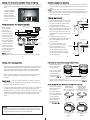
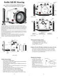
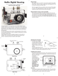
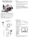
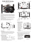
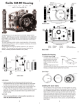
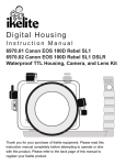
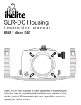
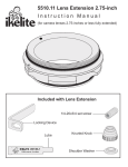
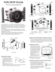
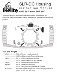
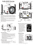
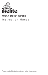
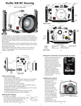
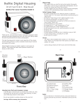
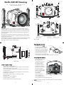
Ikelite SLR-DC Housing
i n s t r u c t i o n
+/-
m a n u a l
Control
Dial
Mode Dial
AEL/AFL
#6856.20 for Olympus E-620
Quick-Release
Strobe
Mount
Info
Button
IKELITE
Port Lock
Gear Sleeve
Drive Gear
Port
Opening
IKELITE
Rubber
Handle
Lid
Snap
Lid
Snap
Strobe
Mount
Aluminum Tray
FRONT VIEW
Viewfinder Port
Fn/AF Target
Buttons
Flash/
Self-Timer
Zoom
Quick
Release
Button
C
B
Congratulations on your purchase of an Ikelite Digital Camera
Housing. Ikelite has over 45 years of experience in the underwater
photographic and lighting market. Our products are designed and
built in the USA by Ikelite for both the professional and amateur
photographer.
The clear housing permits instant visual inspection of the camera
and all sealing surfaces as well as complete monitoring of controls
and camera LCD screens.
Ikelite Digital Housings are slightly negative in salt water for stability. This housing has been water pressure tested at the factory.
Housing is pressure tested to 200’ (60m).
D
E
F
OK
A
G
Lens
Release
[A] Strobe Conn./ Waterproof Cap
[B] Menu button
[C] On/Off Switch
BACK VIEW
Shutter
Release
H
I
[D] Playback
[E] Live View
[F] Arrow Pad/OK
2
[G] Erase
[H] Image Stabilizer
[ I ] Flash Mode Buttons
Opening the Housing
Lid
Snap
Port Lock
Back O’ring
AEL/AFL
Gear
Sleeve
Fn/AF Target
Optional
Port
Shutter
Release
Camera
Tray
Port
O'ring
Camera
Mounting
Bolt
SIDE VIEW
Initial Camera Setup
- Insert a fully charged battery.
- Insert memory card (1GB or greater capacity recommended).
- Set the mode dial to “M” manual.
- Set shutter speed to 1/60th second or 1/125th second for fast
moving subjects.
- Set aperture to F8 for general photography or F22 for macro
photography (close-ups).
- Set Quality to highest jpeg “LF” setting or RAW.
- Set ISO to 100.
- Set Meter to “center-weighted”.
- Set White Balance to “Auto”.
- Set AF mode selection to single AF (S-AF).
3
Lid Snaps have a Lock.
Push Forward
To open, push Lid Snap Lock
Lid Snap Lock
forward and lift as shown.
Keep pressure on the Lid Snap
so it does not fly open quickly.
Some lid snaps have a lot of
Lift
spring tension once they go
over center, so have a firm grip
on the lid snap. Lid Snaps may be opened one at a time. .
Attaching the Camera
Remove the back from
the housing. The
O‘ring
mounting tray for the
camera is secured to
OLYMPUS
the housing back.
Position the camera
E-620
and lens on the tray,
iS
and then secure it with
the mounting bolt
which threads into the
camera’s tripod socket.
Use a flathead
screwdriver
Camera
(recommended) or
Mounting Bolt
Tray Leveling
Tray
coin to tighten the
Screw
mounting bolt, so the
camera bottom is flush against the tray.
IMAGE
STABILIZATION
NOTE: Conversion Circuitry Strobe ID Switch is located on bottom
of camera tray.
4
Setting the Conversion Circuitry Strobe ID Switch.
On the bottom of the camera tray is a switch for setting the DS
Substrobe ID. Set the switch to the Model of DS Substrobe being
used.
• When using dual
strobes of different
models such as a
DS51 and a DS125,
set the ID switch to
DS51 or the smaller
strobe.
DS 50/51
80
125
DS 160
Set
DS Substrobes
to TTL Mode
200
Flash Connection for External Strobes
External Strobe Connector
When using an
and Waterproof Cap
external strobe,
O'ring
connect the
Housing Back
housing hotshoe
connector. Slide the
connector into the
hotshoe mount on
Hot Shoe
the camera, from the
Connector
back of the camera
as shown. Slide the
Mounting
connector forward
Tray
until it stops. This
can be done before
or after the camera is
secured with the
mounting bolt.
NOTE: Make sure
the hotshoe is pushed all the way forward on the camera mount.
5
Closing the Housing (cont.)
Once the camera is installed and the lid snaps have been closed,
make sure the lid-snap lock tab is vertical to the lid-snap, and is
properly engaged. You should be unable to open the lid-snap
when the tab is properly engaged and in it’s locked position.
Make sure the remaining housing controls are returned to their
proper operating position. Check operation of all housing
controls.
Double check - Once the housing is closed, check the o’ring seal.
Note that the gap between the housing back and the housing
should be even all the way around.
Look through the clear plastic back at the o’ring. You should see
a darkened area where the o’ring is compressed against the
housing back. If you do not see an even black compression seal
all the way around the back, open the lid snaps, reseat the housing back, and then close the lid snaps. Visually check the seal
again.
Caution:
Do not remove the External Strobe Connector waterproof cap
unless an external sync cord is going to be plugged in. Do NOT
remove waterproof cap or sync cord underwater.
7
Installing Camera in Housing
Before installing the camera, pull out on the controls in the front
section of the housing. This will allow the camera to slide in more
easily.
NOTE: The AEL-AFL, Info, and Fn controls must be pulled all the
way out. After you insert the camera into the housing front, carefully push in the the controls so that they will properly operate
the corresponding camera buttons.
Closing the Housing
1. Place housing face down in your lap.
2. Check to see that there is an o’ring
on the housing back that is clean
and in it’s proper location.
3. Guide the back onto the housing.
The o’ring should touch the housing
all the way around. There should
be an even gap all the way around
between the housing and the hous- housing
ing back.
4. Lift the lid snaps so they are
extended and place the lid snap into
the corresponding hook on the
housing back.
5. To close the housing, push
down on the lid snaps until
even gap
they snap into place . Lid
all 4 sides
snaps on opposite sides of
the housing should be closed
at the same time. Be sure they
are down far enough to engage
housing
Figure B-Type 2 Lens
the lid-snap lock.
housing back
o’ring
housing back
o’ring
6
Figure A-Type 1 Lens
Preparing to Install Zoom Clamp & Gear Sleeve
Determine the type
of lens being used
on the camera.
Type 1 Lenses have
a lens opening that
is NOT larger in
diameter than the
zoom ring. (Fig. 1).
lens
opening
zoom
ring
Type 1 lens
(Figure 1)
bayonet
mount
Type 2 lens
(Figure 2)
Type 2 Lenses have a lens
opening that IS larger in diameter than the zoom ring. (Fig. 2).
Zoom Clamps & Gear Sleeves Included with Housing
F
There are 2Figure
different
Zoom Clamps and
Gear Sleeves
provided with the
housing. Start with
the suggested Zoom
Clamp and Gear
Sleeve depending
on the Type of
lens being used.
See (Fig. A or B)
Normally used with
Figure G
Type 1 lens
(Fig.1)
#9059.8 small diameter clamp:
For use with #0073 sleeve
wide
grooved
extension
tabs
+
thick ribs
#0073 sleeve: Use with
small diameter zoom clamp
#9059.8
8
Figure A
Normally used with
Type 2 lens (Fig.2)
#5509.28 Package
#9059.9 large diameter clamp:
For use with #0073.1 sleeve
narrow
grooved
extension
tabs
+
thin ribs
#0073.1 sleeve: Use with
large diameter zoom clamp
#9059.9
Figure B
Type 1 Installation: Figure B
Installing the Zoom Clamp & Gear Sleeve On the Type 1Lenses
The Zoom Clamp has springs so it can be expanded to fit over
the Zoom Ring of the lens as shown in (Fig. C).
Install the Zoom Clamp with the extension tabs toward the rear
element of the lens. After installing the Zoom Clamp and Gear
Type 1 Installation:
(Fig. DFigure
& EA), install the Lens Port and rotate the Zoom
Sleeve
Ring on the lens. If the Zoom Ring and Gear Sleeve do not mesh
properly, install the rubber strips (supplied) to the inside diameter of the Zoom Clamp as shown (Fig. F).
Two thicknesses of rubber strips are provided. Start by installing
the thinnest rubber strips. If the Zoom Clamp still is not tight
enough and meshes improperly with the Gear Sleeve, use the
thicker rubber strips. Reinstall the Zoom Clamp, Sleeve, and
Port. Mesh Gear Sleeve teeth with Black Housing Drive Gear
(Fig. G-Page #12)
Type 1 Lenses (continued)
Gear Sleeve
ribs
Align with
Zoom Clamp
grooved tabs
Type 1 Installation: Figure C
Type 1 lens
mounted
to camera
Figure D
Figure B
zoom
ring
apply
rubber strips
to inside of
clamp
Figure C
9
Figure F
Figure E
Figure A
Figure C
Installing the Zoom Clamp & Gear Sleeve On Type 2 Lenses
Due to the larger diameter lens opening on Type 2 lenses, the
Zoom Clamp and Gear Sleeve need to be installed from the rear
(bayonet end) of the lens. Use the housing Lens Release Control
and remove the camera lens from the camera body, after the
camera and lens have been installed in the housing.
Type 2 Installation: Figure 1
10
NOTE:
Before installing the lens port and checking operation, make sure
the teeth on the Gear Sleeve mesh with the teeth on the housing
Drive Gear (Fig. G). When the port is installed, it will lock the
Gear Sleeve in place. After installing the port, rotate the housing
Zoom Control Knob to see that the Gear Sleeve is properly rotating the lens Zoom ring.
Lens Zoom Ring
Lens Manual
Focus Ring
IKELITE
Zoom Clamp
Align
Zoom Clamp
grooved
tabs with
Gear Sleeve
ribs
Gear Sleeve
TOP OF HOUSING
Mesh
Gear Sleeve
teeth with
Black Housing
Drive Gear
Manual Focusing Note:
Type 2 lens
Ikelite DSLR housings are designed for auto-focus DSLR
cameras and lenses. Manual focusing is not recommended. If
you desire to manually focus a lens, the zoom clamp must be
moved onto the lens Manual Focus Ring and you must use the
housing zoom control knob to manually focus. This will result in
loss of zoom capability.
11
Figure G
12
Installing the Port
There are two port locks on
the front of the housing
(See housing front). Each
port lock has a Release
Button. Lift the release button and slide each Port Lock
away from the port opening.
In the unlocked position, the
Release Button will remain
in the up position as shown.
Port Lock
Release
Button
Locked Position
Lift Release
Button to
Unlock
Pull Back to
Disengage
Port
To prepare the port for
installation, remove the port o’ring and lightly lubricate it. The
port seal is a side-to-side seal and requires the o’ring to be lightly lubricated for easy installation. Put a small amount of
lubricant on your fingers and pull the o’ring through your fingers to lightly lubricate it. Do not stretch the o’ring. Check that
the lip of the port where the o’ring fits and the sealing surface
on the housing are clean. Place the port, with o’ring, into the
housing port opening. Press down on the port firmly and evenly
until you feel the port slide into place. Continue to push down
on the port and push each port lock forward until it clicks into
place. It may help to slightly rotate the port as you push in on
each port lock. When the port lock clicks into place, the Release
Button will drop down against the port lock.
Check around the perimeter of the port seal to see that the
o’ring is properly sealed and not extruded (Page 14 - Fig. 2).
Mounting the External Tray and Handles
Turn the housing upside down so the threaded inserts on the bottom of the housing are facing up. Place the aluminum tray onto
the bottom of the housing. Make sure the finger grips on the handles are facing toward the front of the housing. Place a tray bushing (plastic spacer) over the end of each bolt and place through the
recessed tray slots. Screw the bolts into the threaded inserts until
the bolts are tight.
NOTE: When tightening the bolts, position the tray so that the
bolts are in the middle of each recessed tray slot, as shown below.
This is important, so you can pull out the AEL-AFL control when
removing the camera from the housing.
Recessed
Tray Slot
15
To Remove Port
To remove the port, lift up on each Release Button and slide the
port lock away from the port.
Port Seal Inside View
If the port is installed before the camera is inserted into the housing, look
from the inside of the housing at the
port seal. Check to see that the o’ring
is properly seated as shown in
figure 1 and not extruded as shown
in figure 2.
Fig. 1
Fig. 2
Caution:
After installing the port, turn the Zoom Control knob on the
housing. If the Zoom Control is difficult to turn, the gear sleeve
may be warped. If necessary, reduce or omit any rubber installed
on the Zoom Clamp (Fig.F on pg.10). If the Zoom Clamp is still
warped, use of the #5509.28 package may be required. (See page
#8)
NOTE: (lens ports)
A lens port must be secured to the housing before entering the
water. Ikelite DSLR housings DO NOT come with a lens port. You
must select the correct port for each lens you will be using underwater. For complete lens/port information and compatibility with
your Ikelite system, go to www.ikelite.com
14
13
Tray Bushing
Installing the Port cont.
Housing Conversion Circuitry
This housing has Conversion Circuitry built into the camera tray
(Page #5). When used with Ikelite DS Substrobes, the
Conversion Circuitry provides real Canon eTTL flash exposure
with over and under-exposure compensation of two f-stops in
half-stop increments.
The Conversion Circuitry also offers 8 manual power settings in
1/2 stop increments.
The Conversion Circuitry is powered by the Ikelite DS Substrobe
when connected to the housing with the #4103.51 single or
#4103.52 dual sync cord.
See page 20 for DS Substrobe compatibility with the Conversion
Circuitry.
Tray Bolt
16
Using the Conversion Circuitry (Set DS Substrboe to TTL mode)
• Mode and Compensation Buttons
The Conversion Circuitry default is set to TTL. To switch between
TTL and Manual Modes, depress both Mode Buttons at the same
time and keep them depressed until you see the desired Yellow
LED Mode illuminate.
• TTL Mode (indicated when the yellow LED directly below TTL is
illuminated). TTL Mode is the default setting. When the DS
Substrobe is powered ON, the yellow TTL LED will illuminate.
None of the Red LEDs will illuminate. This indicates that no (+)
plus or (-) minus compensation is selected. Depress the Mode
buttons to select +/- compensation. Note that the TTL +/- compensation values are in the yellow bar with the heading TTL.
• Manual Mode (indicated when the yellow LED directly below
the M is illuminated). When the Manual Mode is selected, the
Red LED directly below the F (full power) will illuminate. Note
that the Manual minus (-) compensation values are in the black
bar with the heading M. (Set DS Substrboe to TTL mode)
Using Non-Ikelite or Ikelite Non-DS Substrobes
(Substrobe 50 , 100 A, 200, 400) with this Housing.
The Conversion Circuitry is automatically disabled when used
with a Non-Ikelite or Non-DS Substrobe. These Substrobes can be
used in their manual mode utilizing any power settings provided
on the Substrobe.
For the best underwater photographic results, we recommend
adding an external DS-digital strobe connected to the housing with
a #4103.51 TTL Sync Cord and a SA-100 Ball/socket arm (Page #19).
Ikelite DS series Substrobes are industry favorites for their warm,
even coverage and lightning fast recycle time. Being farther from
the camera lens, the optional DS Substrobe aids in reducing the
illumination of particles in the water and helps to eliminate
backscatter. When used in conjunction with the EV-Controller, the
DS51 Mode switch is set to the TTL setting and the EV-Controller
provides ten power settings in half-stop increments.
Substrobe DS51
The Substrobe DS51 covers the equivalent of a 28mm lens. It is the
ideal choice for macro and general underwater photography.
ikelite
SUBSTROBE
DS
51
Substrobe
DS51
ikelite
18
17
NOTE: DS Substrobe Update information
Substrobe DS160
The Substrobe DS160
covers the equivalent of an
18mm lens or 100 degrees
w/diffuser installed. It is
the ideal choice when
using accessory wide angle
lenses greater than 28mm.
It also features a 1.5 second
recycle time and 225
flashes per full charge. A
superbright built-in 5-watt
LED modeling light is
perfect for focusing or
night diving, all with
minimal drain on the
strobe battery.
Using Ikelite DS Digital Strobes
DS50 Substrobes
• DS50 SubStrobes with a Serial Number below 63,850 can not be
updated to operate with the Conversion Circuitry.
• DS50 SubStrobes with a Serial Number between 63,850 and
69,999 operate with the Conversion Circuitry, but require an
update to provide optimum performance.
• DS50 Substrobes with a Serial Number of 70,000 or higher, or
with one of the two following
labels in the battery compartikelite
ikelite
ment provide optimum
Substrobe
Substrobe
performance with the
MOD-NC
MOD-NC
Conversion Circuitry and do
serial number
not need an update.
Fuel
TTL Full
Test
Guage
-1
3
-2
Off
Ready Light
2
-3
On
On
w/Lite
-4
1
DS
160
SUB
STROBE
Substrobe
DS160
The SA-100 system #4086.61
with its 1" diameter ball is ideal
underwater. The #9571.3
extended stem mount allows
easy attachment of a flashlight
mount, and drops right into
the release handle. Flashlight
aim does not change when
moving the arm to change the
aim of the strobe. The complete system removes with a
push of the handle button.
ikelite
SA-100 Ball/Socket Arm
SA-100 Ball/Socket
Arm #4086.61
#9571.3 Extended
Stem Mount (included
with SA-100
Ball/Socket arm)
19
DS125 Substrobes
• DS125 Substrobes with a Serial Number below 2,500 must be
updated to operate correctly with the Conversion Circuitry.
• DS125 Substrobes with a Serial Number between 2,501 and
4,900 will operate with the Conversion Circuitry, but require an
update to provide optimum performance.
• DS125 Substrobes with a Serial Number of 5,000 or higher, or
with one of the two following labels in the battery
ikelite
ikelite
compartment,Substrobe
provide optiSubstrobe
mum performance with the
MOD-NC
MOD-NC
serial number
Conversion Circuitry and do
not need an update.
To Update Your Substrobe:
Send to the Ikelite address on the back page of this manual or
contact Ikelite for more information.
20
Recommended Strobe Packages
Substrobe DS-51 Package #3944.51 includes #4086.61 Arm System
with Ikelite TTL sync cord.
Substrobe DS-160 Package #3944.90 (Recommended) includes
#4086.61 Arm System and 1.5 hour Smart Charger with Ikelite TTL
sync cord.
Substrobe DS-20 0 Package #3944.60 includes #4085.26 Arm
System and 1.5 hour Smart Charger with Ikelite TTL sync cord.
Please Read If Using an EV-Controller
TTL flash control is not available when using an EV-Controller,
and therefore an EV Controller is NOT recommended for use
with this housing.
NOTE: The EV-Controller cannot be used as a slave. If hard-wired
to the housing, the EV-Controller must be set to Non pre-flash.
Lubricants
1. Ikelite provides silicone lubricant with the housing. We recommend that you use only Ikelite lubricant. Other brands may
cause the o’ring to swell and not seal properly.
2. Use only enough Ikelite lubricant to lightly cover control shafts
and o’rings. Wipe off any excess lubricant with a clean cloth.
Lubricant is not a sealant and is used to reduce friction.
Excessive lubricant can collect sand and dirt which may interfere with proper sealing.
Note: Lubricant is not needed on the main housing o’ring to maintain a housing seal, however, lightly lubricating this o’ring can
extend it’s life and aid in seeing a good housing seal. Too much
lube can attract debris increasing the potential for a leak.
CAUTION: Never use spray lubricants as the propellant ingredient
can cause the plastic housing to crack.
21
Control Maintenance
Ikelite controls are designed to provide years of reliable service
with minimal maintenance.
1. Push button controls require no maintenance other than rinsing
in fresh water after saltwater use. If a push button control
becomes difficult to push or if it sticks when depressed, soak the
housing in luke warm fresh water. After a few minutes, operate
the push button. If this does not correct the problem, return the
housing to Ikelite for maintenance.
2. Some of the controls have long shafts. These controls can be
pulled out, exposing the shaft (see Diagram B on page #24).
To lubricate the control, gently pull on the knob until the
stainless steel shaft is exposed. Lightly lubricate the shaft, then
move the shaft in and out several times. This will lubricate the
x-ring in the Ikelite control gland. This should be done before
using the housing after a prolonged storage period, or once a
week when the housing is in constant use.
3. Some of the controls have a short shaft and cannot be pulled
out exposing the shaft for lubrication. In the unlikely event one
of these controls sticks or becomes difficult to operate you can
remove the control from the housing and lubricate it, or return
the housing to Ikelite for maintenance. To remove the control
(see Diagram A on Page #24), loosen the set screw in the knob
(allen wrench required); remove the knob. If there is salt or dirt
build-up on the exposed control shaft, clean the shaft. Open the
housing and gently slide the control shaft out of the control
gland. Clean and lightly lubricate the shaft, including the end of
the shaft.
23
Optional Accessories
Lead Weight #0 90 6.58
The buoyancy of the system will depend on the size and number
of strobes used, as well as the weight of the camera. Ideally, the
system should be slightly negative in the environment in which
it will be used. If you need to add weight to the system, an
optional lead weight is available. To add the lead weight remove
the (2) screws from the bottom of the aluminum tray. Place the
lead weight into the pocket of the aluminum tray and reattach.
#5512.68 O-ring Kit (recommended) Includes:
Ikelite Lube #0184.1
Port O’ring #0105
Main Housing O’ring #0132.59
While both the Port and Main housing o’rings should last quite
some time, it is best to carry a spare, in case one becomes
damaged or lost.
Storing the Housing
When the housing is going to be stored for a prolonged period it
should be soaked in a mild soap solution, rinsed and dried thoroughly. Remove the back and port from the housing. Remove
the back and port o’rings, lightly lubricate them and place them
in a plastic zip-lock bag. Place the plastic bag inside the housing
for storage. Operate the push buttons periodically.
Pre-Dive Your System
It is recommended that you take the complete system into a
swimming pool before use in open water. This will give you a
chance to become familiar with the handling and operation of
your housing and strobe(s).
22
Control Maintenance Cont.
3. Slide the shaft back into the control gland and gently slide it
back and forth a few times without fully removing the shaft
from the gland. Replace the knob noting the flat area on the
shaft. The set screw in the knob should tighten down against
the flat area on the control, so the knob does not turn on the
shaft.
housing
gland
control
Tighten set screw down
against this flat area
when replacing the knob.
Lubricate end of shaft
before reinserting into
gland
Loosen set screw
Diagram A
lubricate shaft
housing
pull out to
expose shaft
24
Diagram B
General Housing Maintenance
Your Ikelite Housing should be given the same care and attention
as your other photographic equipment. In addition to normal maintenance, we recommend your housing be returned to Ikelite (every
2-3 years or 50 dives), to be checked and pressure tested.
1. Do Not leave the camera and housing in direct sunlight for prolonged periods. Heat may damage the camera.
2. Do Not ship the camera in the housing.
3. Before using the housing, always check the tightness of the set
screw in each control knob.
Check each control gland penetrating the housing to make sure
they are tight. There is a slight chance that either could vibrate
loose during travel.
4. Keep the back and port o’ring clean and lightly lubricated. To
lubricate, remove the o’ring from the back. Put a small amount
of lkelite lubricant on your fingers. Pull the o’ring through your
fingers to apply a light coating of lubricant. Only apply enough
lubricant to make the o’ring feel slick. Do Not stretch the o’ring.
This light coating of lubricant will help to keep the o’ring from
drying out and will help to show a dark sealing line when the
housing back is properly sealed.
5. Keep the area where the o’ring fits and the sealing surface clean.
6. Rinse the housing exterior thoroughly in fresh water after each
salt water use. Depress push buttons several times during rinse.
Dry with a soft cloth. Dry port to eliminate water spotting.
After several uses in salt water, soak the housing in a mild soap
solution, rinse, and dry.
7. Although not recommended, if it is necessary to remove a housing push button, Do Not re-use the E-clip. Contact Ikelite for
replacement E-clips (part #0319.12).
CAUTION: Never use spray lubricants as the propellant
ingredient can cause the plastic housing to crack.
General Tips
1. You should completely assemble and test your system in a
swimming pool before using it in openwater.
2. It is a good idea to start each photo dive with a fully charged
battery in the camera and strobe(s).
3. As soon as you enter the water, take a moment and check the
housing to see that it is properly sealed. Next, check to see if
there are any bubbles on the face of the port. If there are, take
your fingers and remove them. If there are bubbles on the lens
port they can produce soft focus spots in your photographs.
4 Set Image Resolution to the Highest JPG format available or
RAW. Higher resolution settings are required for printing. High
resolution images can easily be reduced in size with software
and retain their original quality. A Low resolution image can be
enlarged with software but much of the quality will be lost.
5. ISO 100 and “center-weighted averaging” metering are recommended.
6. Digital images are usually transferred to the computer where
their appearance can be fine tuned. Many of the image manipulation programs make you think you can magically correct any
image taken and make a good picture. One thing to be aware of
is that if an image is overexposed, some of the color information in the file is missing. If the color is missing you cannot
adjust it. If images are underexposed, the color and detail may
be there, it is just dark, and you can adjust it to some degree. So
if you error in exposure it is better to have the image slightly
underexposed rather than overexposed.
25
26
1. The number one rule in underwater photography is to eliminate
as much water between camera and subject as possible. Get
as close as you can to the subject, then use the zoom. If you
are using flash, subjects beyond 6 feet (1.8m)will not have
much color, regardless of the strobe’s power.
All Ikelite products are warranted against any manufacturing
defects for a period of one year from the date of purchase.
Defective products should be returned prepaid to Ikelite. Ikelite
will, at its discretion, repair or replace such products, and will
return to customer prepaid. All other claims, of any nature, including but not limited to bulb failure are not covered. Except
as mentioned above, no other warranty expressed or implied,
applies to this Ikelite product.
Photo Tips
2. Many digital cameras have a slight lag time between when you
press the shutter release button and when the camera actually
takes the picture. It only takes a slight amount of pressure to
operate the shutter. If the shutter doesn’t trip immediately,
don’t push down harder on the shutter control, as you may
damage the camera. Hold the camera steady a second or two
after pressing the shutter release button.
3. Do not shoot down on subjects as they will quite often blend
into the background and be difficult to see in the photograph.
Shoot subjects straight on, or shoot up at a slight angle using
the blue water as a contrasting background.
4. Underwater flash is used to restore the warmer colors filtered
out by the water as well as to illuminate the subject.
5. For balanced lighting, meter the background and set the camera
aperture accordingly. Use TTL, adjust the strobe’s power settings, or move the strobe closer or farther away to properly
expose the subject with the chosen camera aperture.
6. Avoid shooting into the sun. This can cause unwanted reflections
or underexposed subjects.
Complete information regarding Ikelite products and optional
accessories available at www.ikelite.com
27
Ikelite Limited Warranty
Returning Products for Service
Ikelite is most interested in preforming any service to assure that
all products perform as intended. For repair or service, return the
product to the address below with your name, address, phone
number and a brief description of the problem. Evidence of
purchase date must be provided to obtain warranty service.
Normal service turnaround time is approximately 2-3 weeks.
Ikelite Underwater Systems
50 W 33rd Street
Indianapolis, IN 4620 8 USA
When returning products, send “attn. Repair Dept.”
317-923-4523
“general questions” e-mail: [email protected]
www.ikelite.com
Digital 6856.20-0 1-0509