1
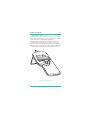
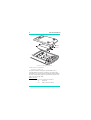
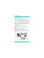
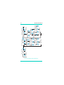
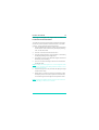
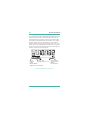
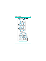
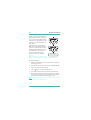
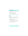
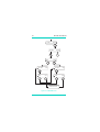
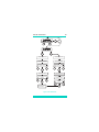
GE Sensing Druck DPI 740 Precision Pressure Indicator User Manual K0200 © The General Electric Company. All rights reserved i DPI 740 User Manual Safety The manufacturer has designed this instrument to be safe when operated using the procedures detailed in this manual. Do not use this instrument for any other purpose than that stated. This publication contains operating and safety instructions that must be followed for safe operation and to maintain the instrument in a safe condition. The safety instructions are either warnings or cautions issued to protect the user and the equipment from injury or damage. Use qualified* personnel and good engineering practice for all procedures in this publication. Pressure Do not apply pressure greater than the maximum safe working pressure to the instrument. Toxic Materials There are no known toxic materials used in this instrument. Maintenance The instrument must be maintained using the manufacturer’s procedures and should be carried out by authorised service agents or the manufacturer’s service departments. Technical Advice For technical advice contact the manufacturer, agent or subsidiary refer to the list at the rear of this manual. * A qualified technician must have the necessary technical knowledge, documentation, special test equipment and tools to carry out the required work on this equipment. This product meets the essential protection requirements of the relevant EEC directives. Further details of applied standards may be found in the product specification. K200 Issue No. 1 DPI 740 User Manual ii Battery Safety This instrument is fitted with three size AA batteries either rechargeable (nickel cadmium) or non-rechargeable (alkaline). Before storing this instrument remove the batteries. When fitting batteries make sure the electrical contacts are clean and observe the correct polarity. The battery compartment should be inspected for corrsion caused by leaking batteries. Corrosion must be removed using approved methods*. When storing and transporting batteries make sure that they cannot be short circuited. A short circuited battery can become very hot and can, in certain circumstances, explode. It is recommended that a suitable container is used for storing and transporting batteries. Dispose of old batteries using a safe, approved method.* *Refer to the Battery Manufacturer for this information. Software Version This manual contains operating instructions for instruments with software version 1.XX. Further changes to the instrument's software may require a change to the operating instructions and an issue number change of the manual. K200 Issue No. 1 iii DPI 740 User Manual Abbreviations The following abbreviations are used in this manual. Note:Abbreviations are the same in the singular and plural. ABS atm BS cmHg CTS DC DCE DTE DUCI ftH2O FS hPa Hz ICAO i/d inHg inH2O ISA kg kgf/cm2 kgf/m2 kPa lbf/ft2 LCD mA mbar mbar a mm mmHg mHg MPa mV acrylonitrile butadiene styrene atmosphere British standard centimetre of mercury clear to send direct current data circuit terminating equipment data terminal equipment Druck Universal Communication Interface feet of water full-scale hecto Pascal Hertz International Civil Aviation Organisation inside diameter inch of mercury inch of water International standard atmosphere kilogram kilogram forceper square centimetre kilogram forceper square metre kilo Pascal pound force per square foot liquid crystal display milli Ampere millibar millibar absolute millimetre millimetre of mercury metre of mercury mega Pascal millivolt K200 Issue No. 1 DPI 740 User Manual iv Abbreviations continued Ni Cad o/d Pa PCB ppm psi QFE QFF QNH RPT RTS RS232 Rx Tx V VA C F nickel cadmium outside diameter Pascal printed circuit board parts per million pound per square inch barometric pressure at airfield level (local) calculated sea level pressure including air temperature calculated sea level pressure resonant pressure transducer ready to send Serial data communication standard receive transmit Volt Volt amp degrees Celsius degrees Fahrenheit Symbols The following symbols are used to identify hazards on this instrument. Static sensitive components handle with extreme care. This symbol, on the instrument, indicates that the user should refer to the user manual. K200 Issue No. 1 v DPI 740 User Manual Table of Contents title page 1 1.1 1.2 Introduction .............................. ...............................................1 Specification.............................. ...............................................2 Accessories and Options...... ...............................................4 2 2.1 2.2 2.3 Installation ................................. ...............................................5 Battery ......................................... ...............................................5 Electrical Connections........... ...............................................6 Initial Settings............................ ...............................................10 3 3.1 3.2 Operation ................................... ...............................................11 General........................................ ...............................................11 Measurement Modes............. ...............................................11 Local (QFE) Measurement.... ...............................................13 Sea Level (QFF) Measurement ..........................................14 Altitude Measurement........... ...............................................16 Processing Measurements.. ...............................................18 Tare ............................................... ...............................................18 Filter .............................................. ...............................................18 Max/Min ...................................... ...............................................21 Set-up Menu.............................. ...............................................25 Battery ......................................... ...............................................26 Units.............................................. ...............................................26 Time-out...................................... ...............................................28 Serial Communications........ ...............................................29 Entering a new PIN................. ...............................................31 Sending Measurements to a Printer or PC .................32 3.3 4 Calibration.................................. ...............................................33 Calibration Check.................... ...............................................33 5 5.1 5.2 5.3 Maintenance ............................. ...............................................37 General........................................ ...............................................37 Fault finding............................... ...............................................37 Cleaning ...................................... ...............................................37 K200 Issue No. 1 DPI 740 User Manual vi Table of Contents (contd) title page 6 6.1 6.2 6.3 6.4 Communications...................... .............................................. 39 Introduction................................ .............................................. 39 General Command Format. .............................................. 40 Command Summary.............. .............................................. 43 Command Set........................... .............................................. 45 Input Commands..................... .............................................. 45 Process Commands............... .............................................. 47 Set-up Commands.................. .............................................. 50 Calibration Commands......... .............................................. 51 Automatic Commands.......... .............................................. 55 Read Commands..................... .............................................. 56 Protocol Format Commands............................................ 58 Key Commands........................ .............................................. 59 Approved Service Agents...................... .............................................. 64 Table of Illustrations fig. 1-1 2-1 2-2 2-3 3-1 3-2 3-3 3-4 3-5 3-6 3-7 3-8 3-9 3-10 title page General view.............................. .............................................. Fitting the battery.................... .............................................. Electrical connections........... .............................................. Adaptor/charger connector Instrument front panel.......... .............................................. Measurement mode menu. .............................................. Local pressure measurement ........................................ Sea level measurement........ .............................................. Altitude measurement.......... .............................................. Process sub-menu.................. .............................................. Max/Min menu.......................... .............................................. Set-up menu.............................. .............................................. Communications set-up....... .............................................. Calibration................................... .............................................. 1 6 8 9 11 12 13 14 16 19 22 25 30 35 K200 Issue No. 1 DPI 740 User Manual 1 1 Introduction The Druck DPI 740 precision pressure indicator uses a silicon resonant pressure transducer producing a pressure reading in units of pressure measurement and altitude. The instrument is contained in a moulded enclosure of a composite ABS material and can be used as a hand-held indicator or, using a retractable stand, as a bench instrument. The instrument can also communicate, through a serial RS232 connector, with a compatible computer system or printer. Figure 1-1 General view K0200 Issue No. 1 2 1.1 DPI 740 User Manual Specification Dimensions Weight: (nominal).................................................................. .................. 0.5 kg Size: height = 190 mm width = 90 mm, depth = 36 mm Environmental Temperature: Operating .......................... ........ ......... ......... -10 to +50 C Storage ......................................................... ......... -40 to +70 C Pressure medium: ................ Any gas compatible with pyrex, .................. .................. silicon, stainless steel and epoxy resin Sealing standard................................................................... .................. IP54 Pressure Connector...................................................... ......... 6 mm o/d or.................................................... ......... 4 mm i/d hose fitting Accuracy Non-linearity, hysteresis and repeatability: over the range of 10° to 30°C ........................................................................... ......... ±0.02 % FS over the range of 0° to 40°C ........................................................................... ......... ±0.03 % FS over the range of -10° to 50°C ........................................................................... .........±0.045 % FS Stability .................................................................. ........ <100 ppm/year Range (barometric)............................................ ........ 750 to 1150 mbar a alternative ranges: .................................................................. ........ 35 to 1300 mbar a .................................................................. ........ 35 to 2600 mbar a .................................................................. ........ 35 to 3500 mbar a Maximum safe working pressure........................ ......... 4375 mbar a Display Read-out................................... .........999999 LCD digits, 13.6mm high .................. .................. with additional 16 text characters Overload indication Error code flashing................. .........at nominal 110% FS Response............................................ ........ nominal 2 readings/second Resolution 0.01 mbar (e.g., 1013.25 mbar a) K0200 Issue No. 1 DPI 740 User Manual 3 Specification (contd) Electrical Power Supply Batteries:...................................................... .........3 x 1.5 V alkaline size AA Connections external power adaptor/charger .............................................. ......... International power jack RS232 serial communications...................... ........ 6-way LEMO type Electrical safety This instrument meets: ............................ ......... BS EN 61010 as applicable Electromagnetic compatibility This instrument meets: ........................................................ ......... EN50081-1 (emissions) ........................................................ ......... EN50082-1 (immunity) Continuing development sometimes necessitates specification changes. K0200 Issue No. 1 4 1.2 DPI 740 User Manual Accessories and Options The instrument is delivered with the following: Accessories i. User manual K200 (this publication). ii. Calibration certificate. iii. Carrying case. Options A Enhanced barometric accuracy over the range of 10 to 30 C ........................................................................... ......... ±0.15 mbar B NiCad batteries and power adaptor/charger Adaptor/charger External Power ............................................... ........ 100 to 240 V a.c. (nominal) .................................................................. ........ 10 VA, 47-65 Hz Output ............................................... ........ 12 Vd.c., 800 mA (maximum) Connection ............................................... ........ International power jack C D Adaptor cable For RS232 connecting the 6-pin LEMO to standard 9-way D type. Transit case K0200 Issue No. 1 DPI 740 User Manual 5 2 Installation WARNING: DO NOT ATTEMPT TO CHARGE NON-RECHARGEABLE BATTERIES. TO PREVENT ACCIDENTAL CHARGING OF NONRECHARGEABLE BATTERIES THE CHARGE LINK LK2 MUST BE IN THE DISABLED POSITION (). CAUTION: DO NOT LEAVE DISCHARGED BATTERIES IN THE INSTRUMENT. OLD BATTERIES CAN LEAK AND CAUSE CORROSION. WHEN FITTING THE BATTERIES MAKE SURE THE ELECTRICAL CONTACTS ARE CLEAN AND OBSERVE THE CORRECT POLARITY. Note: For further information, refer to the safety page at the front of this manual and to the battery manufacturer. 2.1 Battery (Figure 2-1) Three batteries are fitted in the battery compartment. For non rechargeable batteries make sure the charging link LK2 is fitted in the disabled position ( ). For rechargeable batteries make sure the charging link LK2 is fitted in the enabled position (). Note: The charging link LK2 is located on the instrument PCB. To access this link remove the top case assembly. To replace the batteries, unscrew the captive screw and slide off the battery compartment cover. Make sure the polarity of the new batteries is correct. If the battery capacity is low the display shows: The battery symbol (approximately 1 hour left). The flashing message Battery Very Low for 15 to 20 minutes. The message Batteries Dead! followed, after a short time, Switching Off!! the instrument then automatically switches off. K0200 Issue No. 1 6 DPI 740 User Manual captive screw Figure 2-1 Fitting the Battery 2.2 Electrical connections (Figure 2-2 and 2-3) The optional adaptor/charger is supplied with a set of interchangeable connectors so that the unit can be used worldwide. To change the power pin adaptor push the adaptor from the charger body, align the replacement adaptor and push onto the charger body. Battery charger This is a two-pole, 2.5 mm, centre pin connector: -ve - centre pin. +ve - outer connector casing. K0200 Issue No. 1 DPI 740 User Manual 7 RS232 connections Option C is the adaptor cable recommended for use with the RS232 serial communication interface. The adaptor cable has, at one end, 6-pin LEMO type connector and, at the other, a 9way D type connector. The instrument's serial communication settings and the data terminal equipment (DTE) settings must be the same. The recommended initial settings are as follows: Baud rate - 9600 Data bits - 8 Stop bits - 1 Parity - none Handshaking - none Adaptor Cable Instrument (DCE) PC (DTE) LEMO connector Pin No. Function D type Connector Flow Function 9-way 25-way Pin No. Pin No. 1 RxD input TxD 3 2 2 CTS input RTS 7 4 3 GND (screen) GND 5 7 4 not used - - - 5 RTS output CTS 8 5 6 TxD output RxD 2 3 Notes 1. The function column for the D type connector uses RS232 terminology with respect to DTE. 2. In the D-type connector DTR and DSR should be connected together as follows: 9-way pin 4 and 6 25-way pin 20 and 6 3. The instrument's serial communication settings can be changed using the set-up menu. K0200 Issue No. 1 8 DPI 740 User Manual Figure 2-2 Electrical connections K0200 Issue No. 1 DPI 740 User Manual 9 k Druc ALL FOR MENTS RU 9 INST . 191-12 o TN PAR Figure 2-3 Adaptor/charger connector K0200 Issue No. 1 10 2.3 DPI 740 User Manual Initial Settings The instrument is shipped with the following settings: Standard Instrument Settings Units of pressure measurement (selected by F2)................................... ........ mbar, inHg, hPa Battery charging link (LK2) .................................... ......... disabled ( ) Calibration link (LK1)................................................... ......... disabled ( ) PIN ..................................................................................... .................. 000 Time-out ................................................................ ........ enabled (1 minute) Option B Instrument Settings Units of pressure measurement (selected by F2)................................... ........ mbar, inHg, hPa Battery charging link (LK2)...................................... ......... enabled () Calibration link (LK1)................................................... ......... disabled ( ) PIN ..................................................................................... .................. 000 Time-out enabled (1 minute) K0200 Issue No. 1 DPI 740 User Manual 11 3 Operation 3.1 General (Figure 3-1) The instrument is switched on by the ON/OFF push-button and powers up in the last selected mode and units of measurement. The instrument "times-out" after a period of one minute if no push-button selections are made. To keep the instrument in the powered-up state the ON/OFF and MODE push-buttons should be pressed together. The display briefly shows a "Timeout Disabled" message. Pressing the MODE push-button steps through the three pressure measurement modes. Pressing the SET push-button steps through the setup menu (described in 3.3). 3.2 Measurement Modes (Figure 3-1) Selecting the MODE push-button, changes the measurement mode between: Local (QFE unprocessed pressure at the pressure port). Sea (QFF calculated pressure at sea level). Altitude (calculated height from pressure datum). Selecting the push-button F2 changes the units of pressure measurement, continuous pressing steps between three preselected units, the display shows the units for each measurement mode. low pass filter tare + - battery condition selected 16 character mode status line selected units SET F1 function selection MODE mode selection F2 function selection Set-up menus ON/OFF control Figure 3-1 Instrument front panel K0200 Issue No. 1 PROCESS see figure 3-6 F1 F2 MODE Change units LOCAL QFE - local pressure K0200 Issue No. 1 F2 SET_QFF Figure 3-2 Measurement mode menu STORE TEMPERATURE SET TEMP=<V> °C STORE HEIGHT Enter Temp SET F2 F2 HT=.....ft (or metres) F1 F1 MODE Change units F2 same as QFE Enter Height ASL F1 PROCESS F1 SEA QFF - sea level pressure SET_ALT F1 F1 SET Enter Datum Dat.=1013.25 mbar F2 STORE PRESSURE DATUM SET Pressure Datum Dat.=1013.25 mbar to QFE MODE Change units feet or metres F2 F2 same as QFE ISA -alt- USER F1 PROCESS F1 ALTITUDE Altitude in feet and metres F2 12 DPI 740 User Manual DPI 740 User Manual 13 Local (QFE) Measurement (Figure 3-3) This is the direct measurement of the absolute pressure sensed at the pressure port. In addition to measuring local pressure the instrument can, with the use of a hose and connection, measure absolute pressure at a system test point. tare + - measurement mode pressing F1 enters PROCESS menu units of measurement press F2 to change between three units. Figure 3-3 Local pressure measurement K0200 Issue No. 1 14 DPI 740 User Manual Sea Level (QFF) Measurement (Figure 3-4) This mode measures the sea level pressure. It is the meteorological presentation (QFF) of barometric pressure at mean sea level and is a calculated value based on the local height above sea level and the local air temperature. Note:QNH is a derivative of QFF without a correction for local air temperature. Setting local height and temperature data These correction factors are entered for a particular site and remain stored in nonvolatile memory to correct the pressure value when Sea (QFF) is selected. The two correction factors are mean height above sea level in metres or feet (units selected in altitude mode) and the local air temperature in °C. tare + - measurement mode pressing F1 steps to PROCESS and SET_QFF menu units of measurement press F2 to change between three units. Figure 3-4 Sea level measurement K0200 Issue No. 1 DPI 740 User Manual 15 Entering Local Height and Temperature Data for Sea Level Pressure Measurements The indicator stores the local height and temperature data used in the sea level pressure measurement in nonvolatile memory. To enter this data proceed as follows: 1. Press the MODE push-button to select sea level pressure measurement mode (confirmed by the display showing "Sea" on the status line). 2. Press F1 to show the measurement menu. 3. Press F2 selecting the SET_QFF parameter (confirmed by the display flashing "Enter Height ASL"). 4. Press either F1, F2 or SET to allow the height to be entered (the display stops flashing). 5. Use F1 to increase the height value and F2 to decrease the height value. Note:Pressing and holding either F1 or F2 changes the value at a fast rate. Pressing and holding MODE and either F1 or F2 accelerates this fast rate. 6. When the height is correct press SET, the display changes to flash "Enter Temp". 7. Repeat steps 4, 5 and 6 to enter the temperature value. The display returns to sea level pressure measurement, corrected using the new height and temperature data. Note:Pressing the MODE push-button steps menu back one setting, allowing a value to be corrected. K0200 Issue No. 1 16 DPI 740 User Manual Altitude Measurement (Figure 3-5) This mode measures the vertical distance between a level and a specific pressure datum. Measurements of altitude are calculated from local pressure according to ICAO standard atmosphere tables defined in BS 2G 199: 1984. The default pressure datum is the ISA, 1013.25 mbar. A user defined pressure datum can be entered by the SET_ALT menu. This datum can be a specified pressure datum known or required by the user such as true sea level pressure or airfield ground pressure at the time of measurement. tare + - datum pressing F1 steps to pressure PROCESS and SET ALT menu used to calculate altitude (default value 1013.25 mbar) units of altitude press F2 to step between feet and metres Figure 3-5 Altitude measurement K0200 Issue No. 1 DPI 740 User Manual 17 Entering a Pressure Datum for Altitude Measurement The indicator stores the pressure datum used in altitude measurement in volatile memory with a default value of 1013.25 mbar. To enter a new pressure datum proceed as follows: 1. Press the MODE push-button to select altitude measurement mode (confirmed by the display showing "ALTITUDE" on the status line). 2. Press F1 to show the measurement menu. 3. Press F2 to change the altitude settings by selecting "SET_ALT". 4. Press F1 if the datum required is the ISA. To enter any other datum press F2. 5. Press either F1, F2 or SET to allow the datum to be entered (the display stops flashing). 6. Use F1 to increase the datum value and F2 to decrease the datum value. Note:Pressing and holding either F1 or F2 changes the value at a fast rate. Pressing and holding MODE and either F1 or F2 accelerates this fast rate. 7. When the datum value is correct press SET, the display returns to altitude measurement corrected using the new pressure datum. Note:Pressing the MODE push-button steps menu back one setting, allowing a value to be corrected. K0200 Issue No. 1 18 DPI 740 User Manual Processing Measurements (Figure 3-6) The instrument can process the measurement results in the following ways: Tare Filter Max/min Tare Each measurement can be individually "tared". The tare function substracts the presently measured value from all subsequent measurements. When the tare function is enabled, the display flashes the tare symbol. To enable and disable the tare function, proceed as follows: 1. Press the MODE push-button to select the measurement to be tared. 2. Press F1 to enter the instrument menu. 3. Press F1 to view the process options. 4. Press F1 again to view the tare options. 5. Press F1 to enable tare or F2 to disable tare. Filter When switched on the low pass filter is applied to all measurements in all three measurement modes. Before switching on, the two parameters of BAND and TIME should be set. Note:When the time constant in the sample is large and the filter is active at power-up, enough time must be allowed for the sample to be received and a stable reading to be displayed. K0200 Issue No. 1 DPI 740 User Manual 19 Local pressure QFE MODE F2 F1 PROCESS Change units F1 TARE MORE F1 ON - OFF F2 F2 F1 FILTER MORE F2 F1 ON - OFF F2 F1 MAX/MIN MORE F1 F2 s MAX MIN t F2 F1 s value units value units t F1 F1 t MIN F1 t OFF MAX s F2 value units F1 s OFF F2 value units Figure 3-6 Process sub-menu K0200 Issue No. 1 20 DPI 740 User Manual Entering the Filter Parameters BAND % of FS is the maximum percentage change in reading that can occur before the filter directly BAND = <value>%FS follows the changing pressure. This F1 F2 parameter can be set between 0 SET and 10% FS. TIME is the time constant of the filter; when a small step change in TIME = ** pressure is applied (less than the F1 F2 band setting), it is the time to reach SET approximately 63% of the final ** = value 0 to 99 value. The final value will be reached in five time constants. » Display returns to pressure measurement Example With the TIME set to 2 seconds, the display shows the full pressure value after 10 seconds. Proceed as follows: 1. Make sure the instrument is in measurement mode and displaying pressure. 2. Press SET twice and status line shows "MAX/MIN FILTER". 3. Press F2 to select FILTER settings. 4. Use F1 and F2 to set the BAND value. 5. Press SET when the display shows the required value. 6. Repeat steps 4 and 5 to enter the TIME value. Pressing SET returns the instrument to measurement mode with the new filter settings stored and ready for use. Note:The filter parameters are nonvolatile and remain stored with the instrument switched off. K0200 Issue No. 1 DPI 740 User Manual 21 Switching the Filter ON or OFF To switch the filter on proceed as follows: 1. Make sure the instrument is in measurement mode and displaying pressure. 2. Press F1 to enter the instrument menu. 3. Press F1 to enter view process options. 4. Press F2 to view the next option (FILTER). 5. Press F1 to view the filter options. 6. Press F1 to switch filter on or F2 to switch filter off. Note: When the filter is switched on, the display shows the symbol. MAX/MIN In normal measurement mode the max/min measurements are recorded as a background task. The store is reset when the instrument is switched on or can be reset at any time Resetting the Maximum/Minimum Store Proceed as follows: 1. Make sure the instrument is in measurement mode and displaying pressure or altitude. 2. Press SET twice (status line shows "MAX/MIN FILTER"). 3. Press F1 to select the MAX/MIN sub-menu. 4. Press F1 to reset the MAX/MIN store and return the instrument to measurement mode. K0200 Issue No. 1 22 DPI 740 User Manual FILTER MORE F2 MAX/MIN MORE F1 MAX F1 max value units F2 MIN F2 min value units F1 F1 MIN OFF MAX F1 F2 F1 return to pressure measurement mode Figure 3-7 MAX/MIN menu K0200 Issue No. 1 OFF F2 DPI 740 User Manual 23 Viewing the Maximum and Minimum Proceed as follows: 1. Make sure the instrument is in measurement mode and displaying pressure. 2. Press F1 to enter the instrument menu. 3. Press F1 to view process options. 4. Press F2 until the status line shows MAX/MIN. 5. Press F1 to view max/min options. 6. Select MAX (F1) or MIN (F2) the status line shows the recorded value. 7. Press F1 then F2 to switch off either the maximum or minimum value. Press F1 twice to view the other maximum or minimum value. Note:The Max/Min options must be reselected after changing to another measurement mode. K0200 Issue No. 1 24 DPI 740 User Manual intentionally left blank K0200 Issue No. 1 DPI 740 User Manual 25 3.3 Set-up Menu (Figure 3-8) To change other less used facilities and background tasks, enter the set-up menu by pressing the SET push-button. Pressing SET again steps to the next sub-menu set. In each sub-menu the function push-buttons F1 and F2 are used to select the required task. SET Instrument enters set-up menu Note: Using the MODE push-button steps back one menu selection. BATTERY F1 battery capacity (%) UNITS F2 configure units of pressure measurement MAX/MIN F1 MAX/MIN function SET ü ý þ reset MAX/MIN store FILTER F2 FILTER function TIME_OUT F1 configure TIME-OUT SET set filter window see processing measurements set: time-out period, time in minutes enable/disable time-out COMMS F2 SET configure RS232 Set: baud rate, data bits, stop bits, parity and handshaking CAL F1 perform CALIBRATION Carry out a one-point calibration Carry out a two-point calibration PIN F2 enter new PIN number PRINT F1 enter print period Figure 3-8 Set-up Menu K0200 Issue No. 1 26 DPI 740 User Manual Battery This sub-menu shows the capacity charge compared to the full charge capacity shown as a percentage in 25% bands. SET sub-menu BATTS UNITS example: Battery75-100% F1 Units F2 When in the local or sea level measurement modes pressing F2 changes the units of pressure measurement between three preselected units, held in nonvolatile memory. When shipped, the instrument's units of pressure measurement are: mbar, inHg and hPa. These units of pressure measurement can be change to any from the following list: 0 - mbar 12 - 1 - bar 13 - mH2O 2 3 4 5 6 7 - Pa hPa kPa MPa kgf/cm2 kgf/m2 14 15 16 17 18 19 torr atm psi lbf/ft2 inHg inH2O20, (20ÐC) - cmH2O 8 - mmHg 20 - inH2O04, (4ÐC) 9 - cmHg 21 - ftH2O20, (20ÐC) 10 - mHg 22 - ftH2O04, (4ÐC) 11 - mmH2O 23 - inH2O60, (60ÐF) K0200 Issue No. 1 DPI 740 User Manual 27 Changing the preselected units of pressure Proceed as follows: 1. Press the SET push-button. 2. Press F2 to select UNITS. 3. Use F1 and F2 move up and down the list of units. 4. Press the SET push-button to select the required unit. 5. Repeat steps 3 and 4 to select the second and third units. Note 1:The storing of the new units takes place when the SET push-button is pressed for the third unit. The indicator then returns to the pressure measurement mode with the three new units stored and available on push-button F2. Note 2:Pressing the MODE push-button steps the menu back one setting, allowing reselection of the unit. Units of Altitude Measurement When the indicator is in altitude measurement mode, pressing F2 changes the units of height measurement between feet and metres. These two units are held in nonvolatile memory. K0200 Issue No. 1 28 DPI 740 User Manual Time-out The time-out period can be set between 1 and 15 minutes (default 1 minute). In the enabled state, if no push-buttons have been pressed, the time-out switches the instrument "off" after the time elapsed. Pressing the ON/OFF push-button "on" resets the time-out and switches the instrument back on. When this function is disabled the instrument can only be switched off by the ON/OFF push-button. Notes 1. The time-out function is disabled in calibration mode. 2. When switching the instrument on, the time-out can be disabled by pressing MODE and on/off push-button together. Adjusting the Time-out Period Proceed as follows: 1. Make sure the instrument is in measurement mode and displaying pressure. 2. Press SET until the status line shows "TIME_OUT". 3. Press F1 to select time-out settings. 4. Use F1 and F2 to adjust to the required time-out period. 5. Press SET. 6. Press F1 to enable (ON) the time-out function and press F2 to disable (OFF) the function. Note:The instrument stores the adjust time-out period as the default value in nonvolatile memory. K0200 Issue No. 1 DPI 740 User Manual 29 Serial Communications (Figure 3-9) The instrument uses RS232 communication parameters as follows: Baud rate - 19200, 9600, 4800, 1200, 600, 300 & 150 Data bits - 7,8 Stop bits - 1,2 Parity - none, even, odd Handshaking-none, software, hardware Notes: 1. The parameters set on shipment are in bold. 2. The instrument stores any adjusted communication setting in nonvolatile memory. 3. To review the current settings select the sub-menu and press the SET key to step through the sub-menu. 4. Pressing the MODE push-button returns the instrument to the previous setting. Setting the communication parameters (Figure 3-9) Proceed as follows: 1. Make sure the instrument is in measurement mode and displaying pressure. 2. Press SET until the display shows COMMS on the status line. 3. Press F2, selecting the COMMS option. 4. Use F1 and F2 to select the required baud rate and then press SET. 5. Repeat step 4 to set the remaining parameters. When all the parameters are entered the instrument uses the new settings immediately and returns to measurement mode. K0200 Issue No. 1 30 DPI 740 User Manual Baud Rate = **** F1 F2 SET Data Bits = * F1 SET Stop Bits = * F1 SET Parity F1 SET HShake F1 SET Exit set-up, display returns to pressure measurement Figure 3-9 Communications set-up K0200 Issue No. 1 DPI 740 User Manual 31 Entering a new PIN The instrument calibration is protected by a PIN, which must be entered before accessing the calibration menu. The default PIN set at manufacture is 000. Changing the PIN Proceed as follows: 1. Make sure the instrument is in measurement mode and displaying pressure. 2. Press SET until the display shows PIN on the status line. 3. Press F2 to change the PIN. 4. Using F1 , F2 and SET to enter the current PIN. 5. Using F1 , F2 and SET to enter the new PIN. 6. Using F1 , F2 and SET to enter the new PIN again. The instrument compares the first new PIN with the second new PIN to verify the entry. 7. If verified successfully the display briefly shows New PIN Accepted on the status line. Note:If not verified the display briefly shows Verify Failure on the status line. K0200 Issue No. 1 32 DPI 740 User Manual Sending Measurements to a Printer or PC The measured pressure or altitude can be sent to a printer or PC through the RS232 communications connector. The instrument sends the current selected measurement mode data. Sending Data Proceed as follows: 1. Set the RS232 communications parameters of the instrument to match the device receiving the data. 2. Press SET until the display shows PRINT on the status line. 3. Press F1 to select the PRINT menu. The display shows the flashing message "Ent Print Period". This is the rate at which measurements are transmitted by the instrument. 4. Use F1, F2 and SET to enter the print period. Pressing SET returns the instrument to measurement mode with the instrument transmitting data at the selected rate. Error Message When an error is detected an error message is sent in the following form: ERRORnn - where nn is a decimal number. Error numbers are: 04 16 32 - K0200 Issue No. 1 Bad data detected by checksum Hardware fault Pressure outside range DPI 740 User Manual 33 4 CALIBRATION The instrument is supplied with a calibration certificate. For the instrument to stay accurate it is recommended that it is checked every 12 months. The recommended equipment for calibration is a compensated deadweight pressure standard or similar equipment to provide the required accuracy. The following procedures should be carried out in a controlled environment by qualified instrument calibration personnel. If the accuracy of the instrument is not within the specification, carry out a calibration adjustment procedure. The manufacturer offers a comprehensive and, if required, NAMAS accredited calibration service. Calibration Check A calibration check should be carried out at chosen intervals. The readings of the instrument should be compared with a pressure standard and, after any adjustments for accuracy (traced to National Standards), the differences recorded. The adjusted differences can then be compared with the required accuracy for the instrument. If necessary a calibration adjustment can be carried out. The recommended procedure is to check at increasing and then decreasing intervals of 0, 20, 40, 60, 80 and 100% of full-scale. K0200 Issue No. 1 34 DPI 740 User Manual Procedure (Figure 3-10) This sub-menu divides into two selections, a one-point calibration and a two-point calibration. CAUTION:THIS INSTRUMENT CONTAINS STATIC SENSITIVE COMPONENTS HANDLE WITH EXTREME CARE. The calibration procedure is protected by a PIN and the CAL option link LK1 located on the PCB. To carry out a calibration LK1 must be in the position. from previous sub-menu set exit set-up menu SET sub-menu CAL. With the instrument connected to an appropriate pressure standard, the calibration sub-menu accessed through the set-up menu. F1 One-point calibration For the one-point calibration the instrument stores the relationship between pressure and output. Important note The calibration carried out at manufacture is a two-point calibration against a pressure standard traceable to National Standards. Carrying out a one-point calibration can significantly down-grade the instrument's accuracy if in doubt consult the manufacturer before proceeding. Two-point calibration This calibration provides a more accurate reading of the applied pressure, the instrument calculating a more complex correction for the displayed reading. K0200 Issue No. 1 DPI 740 User Manual 35 no Enter PIN F2 F1 1 VALID ? SET 123 CAL. points yes 2 F2 F1 APPLY PRESS - P1 APPLY PRESS - P1 ENTER APP. PRESS ENTER APP. PRESS <value><units> <value><units> F2 F1 F2 F1 SET SET APPLY PRESS - P2 repeat procedure above ENTER CAL. DATE 01/01/96 ENTER CAL. DATE F2 F1 SET 01/01/96 F2 F1 Exit set-up, display returns to pressure measurement SET Figure 3-10 Calibration K0200 Issue No. 1 36 DPI 740 User Manual Two-point calibration Proceed as follows: 1. Make sure the instrument is in measurement mode and displaying pressure. 2. Press SET until the display shows CAL on the status line. 3. Press F1 to select the CAL menu. 4. Use F1, F2 and SET to enter the PIN. 5. Press F2 to select a two point calibration, the display prompts for the first calibration point. 6. Adjust the pressure standard for the first calibration point. 7. Use F1 and F2 to set the first calibration value. 8. When the pressure is stable press SET to enter the first calibration point. The display prompts for the second calibration point. 9. Repeat steps 5 to 7 for the second calibration point. 10. Press F1 to accept the calibration values, the display prompts for the calibration date. 11. Use F1 and F2 to set the calibration date. K0200 Issue No. 1 DPI 740 User Manual 37 5 Maintenance 5.1 General User maintenance on this unit is limited to battery replacement, fault finding and cleaning. 5.2 Fault finding Displayed error messages If the pressure sensed by the instrument exceeds 110% of the full-scale pressure value the display flashes the message OVERRANGE ERROR. Reduce the applied pressure until the error message goes out. If the calibration or set-up of the transducer or the instrument's operation becomes corrupted the display shows SYSTEM ERROR. Return the instrument to the manufacturer or agent for repair. 5.3 Cleaning Clean the case of the unit with a damp lint-free cloth and mild detergent. Make sure that there is no debris in the pressure port. K0200 Issue No. 1 38 K0200 Issue No. 1 DPI 740 User Manual DPI 740 User Manual 39 6 Communications 6.1 Introduction The instrument can be used either in direct mode or as part of a network, in the addressed mode. The communications protocol used by the instrument is the Druck Universal Communication Interface (DUCI). In this section the commands that apply to the instrument are detailed and described, for further information contact Druck. Direct Mode One instrument can be connected directly to a control computer with no addressing is required. Addressed Mode The instrument can be connected into a network of devices, each device has a unique address (0 to 99). The network consists of a ring with the transmit line of one device connected to the receive line of the next device. Hardware and software handshaking are not supported. K0200 Issue No. 1 40 DPI 740 User Manual 6.2 General Command Format The instrument is controlled by a sequence of letter codes, some commands require numeric values to follow the letters. The correct number of parameters must be sent for the particular command. The instrument accepts upper-case or lower-case letters. Commands should be in the form: <start>ddssxx:<CS><terminator> where <start> is the start of a command block indicator that can be * or # character. The * character causes all command block data to be echoed around the network. The # character suppresses the echoing of the data block and can be used for commands such as AA automatic addressing. dd is a two digit destination address 00 to 99 ss is a two digit source address 00 to 99 xx is a two character command. This can be followed by additional data, a number can be added to this command to select a channel. <CS> is a block checksum and takes the form: NN where NN is a two digit checksum that is the modulo 100 sum of all the ASCII codes of the character in the string including the `:`. This checksum feature can be disabled so that Note: the instrument does not use checksums, in which case the checksum must not be sent. When the checksum feature is enabled, commands are only interpreted if the checksum is correct. An error is reported if an incorrect checksum is received. <terminator>is the string termination characters <CR><LF> K0200 Issue No. 1 DPI 740 User Manual 41 The address 99 is a global address recognised by all instruments. As characters are received by the instrument they are instantly echoed on to the next instrument unless the command block character is a `#`. On receiving the termination characters the received destination address is checked for the global address 99 or against the instrument's address. If this matches the command is interpreted or the command is ignored. Commands can be stringed together in a data packet. This allows a more efficient data transfer as the destination and source addresses do not have to be sent with each command. example #0099IC=PIU=0<CR><LF> The command separator `;` can be used: example #0099IC=P;IU=0<CR><LF> This command sent by instrument 99 to instrument 00 to setup input channel to measure pressure and select pressure units of mbar. Query facility In addition to sending commands to instruments, data can be queried by adding the ? character to the command. example #0099IC?<CR><LF> This command interrogates instrument 00 for the parameter on input channel 1. Replies from the instruments follow a similar pattern except the start indicator is different. Replies are echoed round the network and not interpreted. !ddssxx<CS><terminator> The following reply sent from instrument 00 to instrument 99 indicates that the input channel is measuring pressure. !9900IC=P K0200 Issue No. 1 42 DPI 740 User Manual example program #sa?; !SA=00; #fa=1; #0099ic=p; query instrument address reply address is 00 put instrument in addressed mode send command to instrument 00 from instrument 99 input channel is pressure #0099pc=~(ir,10,1); set-up process channel to filter 'input reading ir time constant 10, band 1' #0099iu=0; units to mbar #0099pr?; get reading from process channel !9900PR1=987.22; reply of pressure in mbar (filtered reading) #0099ir?; get unfiltered reading !9900IR=987.22; reply of pressure in mbar #0099iu=18 units to inHg #0099pr?; get reading from process channel !9900PR1=29.153; filtered pressure reading in inHg #0099fa=0; take QFF addressed #iu?; query units !iu=18; units = 18 = inHg (see table 6-1) This example is reproduced using QBASIC in Table 6-3. K0200 Issue No. 1 DPI 740 User Manual 43 6.3 Command Summary The following functions can be performed using the serial link: Input Commands IC=<param type> IR? IU=<index> IA=k Set-up input Get input reading Set-up input units Enable automatic sending of input reading Process Commands PC =<process definition> Set-up Process PC =~(IR),<value>,<value> filter PC =T(IR) tare PC =T(IR),<value> PC =<(IR) maximum PC =>(IR) minimum PC =Q(IR),<value>,<value> QFF PC =A(IR),<value> altitude PR ? Get process reading PA =k Enable automatic sending of process reading PM Reset process maximum and minimum values Instrument Set-up Commands SA=<nn> SUn=<units index> Set instrument address Set-up regular units Calibration Commands CT=<cal type> Specify calibration type CP=<value>[,<temperature>] Enter calibration point CN? Get no. of calibration points reqd. CA Calibration accept CX Calibration abort CD Calibration date K0200 Issue No. 1 44 DPI 740 User Manual PIN commands PP=<pin> Automatic Commands AA=<device address> AE=<error mask> PIN protect command Automatic device address Automatic error reporting Read Commands RB? RI? RE? Read battery volts Read instrument type and version number Read error status Protocol Format Commands FC=<flag> FA=<flag> Enable/disable message checksum Enable/disable addressed mode Key Commands KM=<flag> K0200 Issue No. 1 Front panel key-pad operating mode DPI 740 User Manual 45 6.4 Command Set All commands are of the format described in 6.2. In the following command description the start and terminating characters have been removed for clarity. Parameters enclosed in [ ] are optional. Input commands Command: IC Format: IC=<param type> - Set-up input Description: Set-up input to measure parameter <param type>, the index `i` specifies the measurand. <param type> can be any of the following: P pressure input I current input V voltage input T temperature input Note:Only use pressure P for this instrument. Query: The corresponding query command allows the interrogation of the currently selected parameter. Example: IC? The instrument replies IC=P (input = pressure) Command:IR - Get input reading Format: IR? Description:Request for a reading Example: IR? The instrument replies IR=<value> where: <value> is the reading in the selected units (e.g., IR=1017.95) Query: This is a query only command. K0200 Issue No. 1 46 DPI 740 User Manual Command:IU - Set-up input units Format: IU=<index> Description: Set-up the units for the input in volatile storage. The units are specified as <index>, defined in Table 6-2. Query: A query of this command returns the index units. IU? Reply: IU = <index> Example: a reply of IU=18 means units are inHg Command: IA - Enable automatic sending of input reading Format: IA = k Description: Enables automatic sending of input reading. The value `k` corresponds to `send every `k`th conversion`. If `k` is 0, the automatic send feature is disabled. Example: IA = 10 send a value every 10th conversion. IA = 0 disable the automatic feature. Query: A query responds with an integer of the automatic send interval in conversions. IA? Reply: IA = 10 Example: K0200 Issue No. 1 DPI 740 User Manual 47 Process commands Command: PC - Set-up process Format: PC = <process definition> Description: This command sets and defines the required process of the instrument. The <process definition> must be in the format shown in the following table: PC =<process definition> Set-up Process PC =~(IR),<value>,<value> filter PC =T(IR),<value> PC =<(IR) PC =>(IR) PC =Q(IR),<value>,<value> PC =A(IR),<value> PR ? PA =k tare maximum minimum QFF altitude Get process reading Enable automatic sending of process reading Reset process maximum and minimum values. PM Process definitions Example: ~ filter PC=~(IR,0.15,0.01) Define filter input reading changing the <time constant> and <band>. Note: This filter does not affect the normal instrument filter. K0200 Issue No. 1 48 DPI 740 User Manual Example: Note: T tare PC=T(IR) Full tare of input reading. PC=T(IR,100.00) Define tare of input reading, subtracts 100 from reading. The value specified in the command is in the currently selected units. This tares the value but does not change the displayed value. Example: < PC=<(IR) Defines the minimum value of the input reading. To reset this value use PM command. Example: > PC=>(IR) Defines the maximum value of the input reading. To reset this value use PM command. Example: Q minimum maximum QFF PC=Q(IR,200,20) Define the derived QFF input value changing both the <height> and <temp> parameters. Example: A altitude (also see command PA) PC=A(IR,120.00) Define the derived ALTITUDE input value changing the current or default setting of <datum pressure> to 120.00. K0200 Issue No. 1 DPI 740 User Manual 49 Command: PR - Get reading Format: Description: Query: Example: PR? Requests the reading. This is a query only command. OR? Reply: OR = 1000.00 reading in mbar Command: PA - Enable automatic sending of reading Format: Description: PA = k Enables automatic sending of input reading. The value `k` corresponds to `send every `k`th conversion`. If `k` is 0, the automatic send feature is disabled. PA = 10 send value every 10th conversion. PA = 0 disable the automatic feature. Example: Query: A query responds with an integer of the automatic send interval in conversions. Example:PA? Command: Reply: PA = 10 PM- Resets process maximum and minimum values (also see PC command `<` and`>`) PM Sets maximum and minimum values equal to the current reading, in effect resetting both values. Query: There is no corresponding query command. Format: Description: K0200 Issue No. 1 50 DPI 740 User Manual Set-up commands Command: SA- Set instrument address Format: Description: SA = <nn> Set instrument address to <nn>. Changes the network address of the instrument in the range 0 to 98. Address 99 is used for global commands. SA=10 set instrument address to 10 Example: Query: SA? Reply: query instrument address SA=10 Command: SU - Set-up "regular" units Format: Description: SUn = <units index> Selects the pressure units that appear as default selection F2 in measurement mode. Both required parameters must be specified i.e. the push-button sequence n (1, 2 or 3) and the <units index>. SU1=0 sets first units (1) to mbar SU2= 18 sets second units (2) to inHg Example: Query: The corresponding query command returns the index to the pressure units selected for the specified option. SU1? Reply: SUn=<units index> SU1=0 K0200 Issue No. 1 DPI 740 User Manual 51 Calibration commands C - User Calibration This command allows the user to perform a two point calibration on the output of the device. The calibration routine requires two pressures to be applied within the operating extremes. The software calculates an offset and gain correction to all subsequent readings. Command: CT - Specify calibration type Format: Description: CT= <cal type> Specify the type of calibration to be performed. The instrument must be in calibration mode before this command becomes valid. <cal type> = 1 two point matching calibration CT=1 perform two point matching calibration Example: Query: A query of this parameter CT? returns the type of calibration in progress. CT? query calibration type Reply: CT = 1 The instrument is now ready for the application of calibration pressure, both the calibration points must be entered to complete the procedure. When the pressure stabilizes, the instrument must be sent the applied value in the currently selected units, using the CP command. K0200 Issue No. 1 52 Command: DPI 740 User Manual CP - Enter Calibration Point Format: Description: CP = <value> The calibration point value is given by <value> in the currently selected units. Query: A query of this parameter CP? returns the number of calibration points already recorded by this command. The instrument also indicates that it is ready for the next calibration point. Reply: example CP = 0 no cal points recorded CP = 2 2 cal points recorded After entering all the points required to calibrate the instrument, the accept calibration command CA must be sent to update the data in the instrument's nonvolatile memory. K0200 Issue No. 1 DPI 740 User Manual 53 Command: CN - Get number of calibration points required Format: Description: CN? Returns the minimum and maximum calibration points required to carry out the specified calibration procedure. Example: IU = 0 set-up input as mbar PP = 123 PIN entered put instrument into calibration mode CT = 1 perform two point calibration CN? Reply: CN=1,2 requires between 1 and 2 calibration points Query: This is a query only command. Command: CA - Calibration Accept Format: Description: Query: CA Accepts the calibrated data. If the correct number of calibration points have been entered with the CP command then the calibration coefficients are calculated and stored in the instrument's nonvolatile memory. The instrument returns to measurement mode. There is no associated query command. Command: CX - Calibration abort Format: Description: Example: CX Aborts the calibration procedure. IU = 0 set-up input as mbar PP= 123 PIN entered put instrument into calibration mode CT = 1 perform two point calibration CP = 200 applied pressure 200 mbar CX abort calibration Query: There is no associated query command. K0200 Issue No. 1 54 DPI 740 User Manual Command: CD - Calibration date Format: Description: CD = <dd/mm/yy> Sets calibration date, only valid in calibration mode. CD = 24/01/97 set cal date to 24 January 1997. Example: Query: CD? Reply: query date of last calibration. CD = 24/01/97 Example of a two point calibration IU = 0 set-up input as mbar PP = 123 PIN entered put instrument into calibration mode CT = 1 perform two point calibration CP = 800 applied pressure 800 mbar CP =1100 applied pressure 1100 mbar CA calibration accepted CD calibration date Command: PP - PIN protection Format: Description: PP = <pin> This command is used to change the PIN of the instrument which is used to protect the calibration data and configuration. <pin> = 123 calibration PIN code Example: PP= 123 PIN entered put instrument into calibration mode Query: There is no corresponding query command. K0200 Issue No. 1 DPI 740 User Manual 55 Automatic commands Command: AA - Format: Description: Example: AA = <device address> This command can only be used with the# command header block. It automatically sets the addresses of the instruments in the network to sequentially increasing addresses. AA = 10 Automatic addressing Query: With three instruments in the network, this command sets the instrument addresses 10, 11 and 12. There is no query for this command. Command: AE - Automatic error reporting Format: Description: AE = <error mask> This command enables error reporting. A 16 bit (hexadecimal) value<error mask> defines the bit image of errors to be acted on if set. If the error occurs, the "RE" error message is automatically. <error mask> is defined in Table 6-1. Note:An automatic error response does not clear the error bit. The RE? command must be issued to clear the error. Example: AE = AE = 0001 an error is reported when a syntax error is generated. FFFF an error is reported for every error. Query: A query responds with a hexadecimal value corresponding to the bit image of the error mask. K0200 Issue No. 1 56 DPI 740 User Manual Read commands Command: RB - Read Battery Volts Format: Description: Example: RB? Read battery voltage RB? query battery voltage Reply: RB = <voltage> RB = 3.9 battery 3.9 volts Query: There is a query only command. Command: RI - Read instrument type and version number Format: Description: RI? Read device equipment, this returns the instrument type on the network including the version of the code, in the form: RI = <string> where: the string is in the format: "DPInnn, Vm.mm" nnn = instrument type m.mm = version and issue number RI? query instrument version and issue number Example: RI = DPI740, V1.10 Query: There is a query only command. K0200 Issue No. 1 DPI 740 User Manual 57 Command: RE - Read error status Format: Description: RE? Report errors. This query command reports any error since the last RE? command. The errors are stored as bits (16 bits max) and set if the error occurred. After issuing this command all errors are cleared. The error codes are defined in Table 6.1. Errors are only set for commands sent to the instrument. All other commands are ignored. where: the string is in the format: Note: Example: RE? reports errors RE = 0000 no errors, since last report. Query: There is a query only command. K0200 Issue No. 1 58 DPI 740 User Manual Protocol format commands Command: FC - Enable/disable message checksum Format: Description: FC=<flag> Format checksum command. Enables/ disables the checksum feature of the data transactions. <flag> = 0 disable checksum feature 1 enable checksum feature FC = 0 disable checksum feature FC = 1 enable checksum feature Example: Query: There is no corresponding query command. Command: FA - Enable/disable addressed mode Format: Description: FA=<flag> Format addressing mode command. Enables/disables the addressed mode feature of the data transactions. When addressed mode is disabled, one to one communication (direct mode) is assumed. <flag> = 0 disable addressed mode 1 enable addressed mode FA = 0 disable addressed mode FA = 1 enable addressed mode Example: Query: There is no corresponding query command. K0200 Issue No. 1 DPI 740 User Manual 59 Key commands Command: KM - Local/remote operating mode Format: Description: KM=<flag> Sets the push-button mode so that the instrument can be operated remotely. This command locks/unlocks the push-buttons. KM = L local mode (push-buttons enabled) KM = 2 remote mode (push-buttons disabled) Example: Query: The query command returns the local/ remote status. KM? query operating mode Reply: KM=L (operating in local mode) or KM=R (operating in remote mode) K0200 Issue No. 1 60 DPI 740 User Manual Table 6-1 Table of Error Definitions The 16-bit hexadecimal mask defined below can be specified using the AE command. It is used for automatic error reporting by the RE message transmitted by the instrument. Bit Error Description 0 syntax error Set if the command syntax was not understood. 1 parameter error Set if the parameters in the command were out of range or not valid. 2 configuration error The configuration parameters can only be changed if the configuration PIN is sent with the commands. If the PIN is not sent or is incorrect this error is reported. 3 address error An invalid address packet was received. 4 checksum The received command checksum did not match error with the calculated checksum. With this error, the command is not executed and this error reported. 5 zero error An error occurred while trying to zero a measurand, probably because the zero offset is too large. 6 calibration error Error in the instrument's calibration procedure; not enough calibration points. 7 sequence error A valid command was received, but can not be processed because the instrument was not in the correct state to execute command. 8 command not available This command was not available on this instrument. 9 range error Reading outside range. 10 reserved 11 reserved 12 reserved 13 reserved 14 reserved 15 reserved K0200 Issue No. 1 DPI 740 User Manual 61 Table 6-2 Table of Measurement Units The <index> used to identify all the units of measurement are defined below and are used by the IU and SU commands. 0 1 2 3 4 5 6 7 8 9 10 11 - mbar bar Pa hPa kPa MPa kgf/cm2 kgf/m2 mmHg cmHg mHg mmH2O 12 - cmH2O 13 - mH2O 14 15 16 17 18 19 torr atm psi lbf/ft2 inHg inH2O20, (20°C) - 20 - inH2O04, (4°C) 21 - ftH2O20, (20°C) 22 - ftH2O04, (4°C) 23 - inH2O60, (60°F) 70 71 - metres feet K0200 Issue No. 1 62 DPI 740 User Manual Table 6-3 Example Program in QBASIC start: EOFch=26 CLS port%=1 PRINT SPC(20); "DPI 740 Druck Iniversal Communications Interface : Example Program" PRINT SPC (19); "==============================================" PRINT PRINT Before commencing, ensure that the DPI 740 Communications Parameters are set as follows:" PRINT PRINT "Baudrate : 9600, Parity : None, Handshaking : None, Databits : 8, Stopbits : 1" PRINT PRINT "The PC serial comms port used is COM"; PRINT port% PRINT PRINT "Please note DOS File Name : Pressure Readings will be Logged in this File" PRINT INPUT Nm$ PRINT PRINT "Ready" PRINT "Press <CTRL><BREAK> to exit" PRINT "Starting communications" OPEN Nm$ FOR OUTPUT AS #2 IF port% = 2 THEN OPEN "COM2:9600,N,8,1,RS,RB6000" FOR RANDOM AS #1 ELSE OPEN "COM2:9600,N,8,1,RS,RB6000" FOR RANDOM AS #1 END IF PRINT "Comm port opened OK" a$="" PRINT #1, "#sa?" = CHR$(13); PRINT #2, "#sa?" = CHR$(13) = CHR$(10); GOSUB GetReply address$=RIGHT$(a$,4) address$=LEFT$(address$,2) K0200 Issue No. 1 DPI 740 User Manual 63 PRINT #1, "#fa=1"+ CHR$(13); PRINT #2, "#fa=1" + CHR$(13) +CHR$(10); PRINT #1, "#" + address$ + "99"+"ic=p" + CHR$(13); PRINT #2, "#" + address$ + "99"+"ic=p" + CHR$(13)+CHR$(10); PRINT #1, "#" + address$ + "99"+"pc=~(ir,10,1)" + CHR$(13); PRINT #2, "#" + address$ + "99"+"pc=~(ir,10,1)" + CHR$(13)+CHR$(10); PRINT #1, "#" + address$ + "99"+"iu=0" + CHR$(13); PRINT #2, "#" + address$ + "99"+"iu=0" + CHR$(13)+CHR$(10); PRINT #1, "#" + address$ + "99"+"pr?" + CHR$(13); PRINT #2, "#" + address$ + "99"+"pr?" + CHR$(13)+CHR$(10); GOSUB GetReply pressure$=RIGHT$(a$,10) pressure$=LEFT$(pressure$,8) PRINT"Pressure of the Day is "+pressure$="mbar"+CHR$(13); PRINT #1, "#" + address$ + "99"+"ir?" + CHR$(13); PRINT #2, "#" + address$ + "99"+"ir?" + CHR$(13)+CHR$(10); GOSUB GetReply PRINT #1, "#" + address$ + "99"+"iu=18" + CHR$(13); PRINT #2, "#" + address$ + "99"+"iu=18" + CHR$(13)+CHR$(10); PRINT #1, "#" + address$ + "99"+"pr?" + CHR$(13); PRINT #2, "#" + address$ + "99"+"pr?" + CHR$(13)+CHR$(10); GOSUB GetReply pressure$=RIGHT$(a$,10) pressure$=LEFT$(pressure$,8) PRINT"Pressure of the Day is "+pressure$="inHg"+CHR$(13); PRINT #1, "#" + address$ + "99"+"fa=0" + CHR$(13); PRINT #2, "#" + address$ + "99"+"fa=0" + CHR$(13)+CHR$(10); PRINT #1, "#iu?" + CHR$(13); PRINT #2, "#iu?" + CHR$(13)+CHR$(10); GOSUB GetReply CLOSE#1 CLOSE#2 END GetReply: a$=""" DO b$=INPUT$(1,#1) a$=a$+b$ LOOP UNTIL b$=CHR$(10) PRINT #2,a$ RETURN K0200 Issue No. 1 64 DPI 740 User Manual Approved Service Agents www.gesensing.com K0200 Issue No. 1