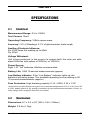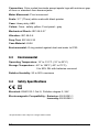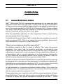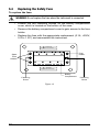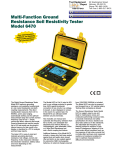
1
3620 GROUND RESISTANCE TESTER X Y Z C1 P2 C2 GROUND RESISTANCE TESTER MODEL 3620 0. 5 25 X-Y Hi Resistance X-Y Hi Noise Press To Measure Ω 1k X-Z Fault ! REFER TO USER MANUAL FOR FAULT WARNING LIGHT EXPLANATIONS ® INSTRUMENTS ENGLISH User Manual Statement of Compliance Chauvin Arnoux®, Inc. d.b.a. AEMC® Instruments certifies that this instrument has been calibrated using standards and instruments traceable to international standards. We guarantee that at the time of shipping your instrument has met its published specifications. An NIST traceable certificate may be requested at the time of purchase, or obtained by returning the instrument to our repair and calibration facility, for a nominal charge. The recommended calibration interval for this instrument is 12 months and begins on the date of receipt by the customer. For recalibration, please use our calibration services. Refer to our repair and calibration section at www.aemc.com. Serial #: _______________________________ Catalog #: _ ______________________________ Model #: 3620 Please fill in the appropriate date as indicated: Date Received: __________________________________ Date Calibration Due: ________________________ Chauvin Arnoux®, Inc. d.b.a AEMC® Instruments www.aemc.com Table of Contents 1. INTRODUCTION................................................................................ 3 1.1 International Electrical Symbols.................................................4 1.2 Definition of Measurement Categories......................................4 1.3 Receiving Your Shipment...........................................................4 1.4 Ordering Information..................................................................5 1.4.1 Kits, Accessories and Replacement Parts.....................5 2. PRODUCT FEATURES....................................................................... 6 2.1 Control Features........................................................................6 2.2 Fault Indicator LEDs..................................................................7 2.2.1 X-Z Fault........................................................................7 2.2.2 X-Y High Resistance......................................................7 2.2.3 X-Y High Noise..............................................................7 2.3 Fault Indicator Tips And Solutions.............................................8 3. SPECIFICATIONS............................................................................. 9 3.1 Electrical....................................................................................9 3.2 Mechanical.................................................................................9 3.3 Environmental..........................................................................10 3.4 Safety Specifications...............................................................10 4. OPERATION................................................................................... 11 4.1 Ground Resistance Values...................................................... 11 4.2 Ground Resistance Testing Principle . ....................................13 4.2.1 Position of the Auxiliary Electrodes in Measurements.14 4.3 Measuring Resistance of Ground Electrodes (62% Method)...15 4.3.1 Auxiliary Electrode Spacing.........................................17 4.4 Ground Resistance Measurement Procedure (3-Point)...........18 4.5 2-Point Measurement (Simplified Measurement)....................19 4.6 Continuity Measurement..........................................................20 4.7 How to Use 25W Calibration Checker......................................20 5. MAINTENANCE.............................................................................. 21 5.1 Warning...................................................................................21 5.2 Cleaning...................................................................................21 5.3 Replacing the Battery..............................................................21 5.4 Replacing the Safety Fuse.......................................................22 Repair and Calibration............................................................................23 Technical and Sales Assistance.............................................................23 Limited Warranty....................................................................................24 Warranty Repairs....................................................................................24 CHAPTER 1 INTRODUCTION WARNING “It should be impressed on all personnel that a lethal potential can exist between the station ground and a remote ground if a system fault involving the station ground occurs while tests are being made. Since one of the objects of tests on a station ground is the establishment of the location of an effectively remote point for both current and potential electrodes, the leads to the electrodes must be treated as though a possible potential could exist between these test leads and any point on the station ground grid.” - excerpted from IEEE Std. 81-1962 These safety warnings are provided to ensure the safety of personnel and proper operation of the instrument. • The instrument must not be operated beyond its specified operating range. • Safety is the responsibility of the operator. • All metal objects or wires connected to the electrical system should be assumed to be lethal until tested. Grounding systems are no exception. • Use extreme caution when using the instrument around energized electrical equipment. • Never attempt to use the instrument to twist or pry the ground electrode or ground wire away from the equipment being grounded. • AEMC® Instruments considers the use of rubber gloves to be an excellent safety practice even if the equipment is properly operated and correctly grounded. • Always inspect the instrument and leads prior to use. Replace any defective parts immediately. Ground Resistance Tester Model 3620 3 1.1 International Electrical Symbols This symbol signifies that the instrument is protected by double or reinforced insulation. This symbol on the instrument indicates a WARNING and that the operator must refer to the user manual for instructions before operating the instrument. In this manual, the symbol preceding instructions indicates that if the instructions are not followed, bodily injury, installation/sample and product damage may result. Risk of electric shock. The voltage at the parts marked with this symbol may be dangerous. In conformity with WEEE 2002/96/EC 1.2 Definition of Measurement Categories Cat. I: For measurements on circuits not directly connected to the AC supply wall outlet such as protected secondaries, signal level, and limited energy circuits. Cat. II: For measurements performed on circuits directly connected to the electrical distribution system. Examples are measurements on household appliances or portable tools. Cat. III: For measurements performed in the building installation at the distribution level such as on hardwired equipment in fixed installation and circuit breakers. Cat. IV: For measurements performed at the primary electrical supply (<1000V) such as on primary overcurrent protection devices, ripple control units, or meters. 1.3 Receiving Your Shipment Upon receiving your shipment, make sure that the contents are consistent with the packing list. Notify your distributor of any missing items. If the equipment appears to be damaged, file a claim immediately with the carrier and notify your distributor at once, giving a detailed description of any damage. Save the damaged packing container to substantiate your claim. 4 Ground Resistance Tester Model 3620 1.4 Ordering Information Ground Resistance Tester Model 3620............................. Cat. #2114.90 Includes soft carrying case, batteries and a user manual. Ground Resistance Tester Model 3620 Kit (150 ft).......... Cat. #2135.10 Includes ground tester, two 150 ft color-coded leads on spools (red/blue), one 30 ft lead (green), two T-shaped auxiliary ground electrodes, set of 5 spaded lugs, one 100 ft AEMC® tape measure, batteries, carrying bag, user manual and warranty card. Ground Resistance Tester Model 3620 Kit (300 ft).......... Cat. #2135.11 Includes ground tester, two 300 ft color-coded leads on spools (red/blue), two 100 ft colorcoded leads (hand tied-green/black), four T-shaped auxiliary ground electrodes, set of 5 spaded lugs, one 100 ft AEMC® tape measure, batteries, carrying bag, user manual and warranty card. Ground Resistance Tester Model 3620 Kit (500 ft).......... Cat. #2135.11 Includes ground tester, two 500 ft color-coded leads on spools (red/blue), two 100 ft colorcoded leads (hand tied-green/black), one 30 ft lead (green), four T-shaped auxiliary ground electrodes, set of 5 spaded lugs, one 100 ft AEMC® tape measure, batteries, carrying bag, user manual and warranty card. 1.4.1 Kits, Accessories and Replacement Parts Test Kit for 3-Point Testing (150 ft)................................... Cat. #2135.35 Includes two 150 ft color-coded leads on spools (red/blue), one 30 ft lead (green), two Tshaped auxiliary ground electrodes, set of 5 spaded lugs, one 100 ft AEMC® tape measure, carrying bag. Test Kit for 4-Point Testing (300 ft)................................... Cat. #2135.36 Includes two 300 ft color-coded leads on spools (red/blue), two 100 ft color-coded leads (hand-tied, green/black), four T-shaped auxiliary ground electrodes, set of 5 spaded lugs, one 100 ft AEMC® tape measure, carrying bag. Test Kit for 4-Point Testing (500 ft)................................... Cat. #2135.37 Includes two 500 ft color-coded leads on spools (red/blue), two 100 ft color-coded leads (hand-tied, green/black), one 30 ft lead (green), four T-shaped auxiliary ground electrodes, set of 5 spaded lugs, one 100 ft AEMC® tape measure, carrying bag. Test Kit for 3-Point Testing (Supplemental for 4-Point Testing)... Cat. #2135.38 Includes two 100 ft color-coded leads (hand-tied, green/black), one 30 ft lead (green), two T-shaped auxiliary ground electrodes, set of 5 spaded lugs, one 100 ft AEMC® tape measure, carrying bag. 25Ω Calibration Checker.................................................... Cat. #2130.59 Tape Measure – AEMC 100 ft............................................. Cat. #2130.60 Ground Tester Video/Workbook Set................................. Cat. #2130.64 Set of 2, T-Shaped Auxiliary Ground Electrodes............. Cat. #2135.39 Fuse – Set of 5, 0.1A, >250V, 0.25 x 1.25"......................... Cat. #2970.12 Ground Resistance Tester Model 3620 5 CHAPTER 2 PRODUCT FEATURES 2.1 Control Features 1 2 3 4 5 X Y Z C1 P2 C2 GROUND RESISTANCE TESTER MODEL 3620 25 0. 5 Ω X-Y Hi Resistance X-Y Hi Noise 1k X-Z Fault 6 ! Press To Measure REFER TO USER MANUAL FOR FAULT WARNING LIGHT EXPLANATIONS 7 ® INSTRUMENTS 11 10 8 9 Figure 1 1. Press-to-measure button 7. Zero adjustment screw 2. Input terminal X (C1) 8. Low battery indicator 3. Input terminal Y (P2) 9. X-Y hi noise indicator 4. Shorting link 10. X-Y hi resistance indicator 5. Input terminal Z (C2) 11. X-Z fault indicator 6. Display 6 Ground Resistance Tester Model 3620 2.2 Fault Indicator LEDs The three LED indicators described below confirm the correct measurement being taken if none of them are lit. 2.2.1 X-Z Fault This LED signals that the voltage between terminals X and Z exceeds 30V peak. There are five possible causes: • the resistance of the current circuit between X and Z is too high • interference voltage in the current circuit is too high • the fuse is blown • the circuit is open (lead not connected) • when the reading is under 0.5Ω (needle on the left of the scale) NOTE: When performing a test this light will initially come on for approxi mately three seconds until the nominal test voltage is reached and then the light will go out if all indications are normal. 2.2.2 X-Y High Resistance This LED signals that the resistance in the voltage circuit (between X and Y) is too high (approximately 50kΩ) or that the circuit may be open. Flashing will continue throughout the measurement, even if the resistance drops below the threshold; for example, after reconnecting or lowering auxiliary rod resistance. In this case, you must release the push-button and press again after the fault has been corrected. Occasionally, a stray voltage above 6VDC may also set off this light. Check the leads for a possible solution. 2.2.3 X-Y High Noise This LED signals the presence of excessive noise (approximately 13V peak) in the voltage circuit (between X and Y). One remedy is to use shielded leads from the instrument to the auxiliary electrodes. Connect all the shields to the rod under test. Ground Resistance Tester Model 3620 7 Galvanometer Pointer • If the pointer stops on the right side, this indicates that you measured more than 1000Ω (over-ranging condition) or that the circuit is open. • If the pointer stops on the left side, this indicates that you measured less than 0.5Ω. This may also indicate that the X and Y rods, or the X and Z rods, were inverted. • Check the connections. 2.3 Fault Indicator Tips And Solutions The LED indicators show excessive electrode resistance and/or excessive transient noise and/or stray current. In the event of an incorrect measurement indication: • Improve the quality of the connection to earth of auxiliary ground electrodes Y and Z. Z is the most likely source of problems caused by excessive electrode resistance. • Check connections for continuity between leads and electrodes. • Be sure that electrodes are properly inserted; they should be buried as much as possible. • If high electrode resistance still exists after properly inserting auxiliary electrodes into the earth, try pouring water on and around the auxiliary electrodes. This will improve their electrical connection to earth. • If stray currents are suspected, one solution to reduce their influence is to move both Y and Z electrodes in an arc relative to the X electrode (try, e.g., a 90° shift), and test again. NOTE: Accuracy may be affected by auxiliary ground rod (Ry, Rz) resistance levels and by stray signal levels (earth currents). 8 Ground Resistance Tester Model 3620 CHAPTER 3 SPECIFICATIONS 3.1 Electrical Measurement Range: 0.5 to 1000Ω Test Current: 10mA Operating Frequency: 128Hz square wave Accuracy*: 5% of Reading ± 0.1% of galvanometer scale length Auxiliary Electrode Influence: Rz: 3000 times the reading up to 50kΩ Ry: 50kΩ Voltage Withstand: Unit is fuse protected. In the event of a system fault, the units can withstand 250Vrms with spikes of 3000VAC or 1000VDC. Power Source: Eight 1.5V “AA” batteries; Alkaline recommended Battery Life: 1680 15-second measurements (approx) Low Battery Indicator: If the “Low Battery” indicator lights up, the batteries are losing power. The available operating time remaining is 80 15-second measurements (approx) Fuse Protection: High breaking capacity 0.1A, >250V, 0.25 x 1.25" *Accuracies and specifications are given for an ambient temperature of 23°C ± 3K, RH of 45 to 55%, battery power at 8V, auxiliary resistance at the measurement terminals <200Ω, no stray voltage and a magnetic field from 0 to 40A/m. 3.2 Mechanical Dimensions: 8.7 x 5.4 x 5.9" (220 x 136 x 150mm) Weight: 2.9 lbs (1.3kg) Ground Resistance Tester Model 3620 9 Connection: Color-coded terminals accept spade lugs with minimum gap of 6mm or standard 4mm banana jacks Meter Movement: Pivot movement Scale: 3.1" (77mm) white scale with black pointer Case: Heavy-duty, ABS Colors: Case - safety yellow; Front panel - gray Mechanical Shock: IEC 68-2-27 Vibration: IEC 68-2-6 Drop Test: IEC 68-2-32 Case Material: UL94 Environmental: O-ring sealed against dust and water to IP50 3.3 Environmental Operating Temperature: 14° to 131°F (-10° to 55°C) Storage Temperature: -40° to 158°F (-40° to 70°C); 0 to 90% RH with batteries removed Relative Humidity: 20 to 90% maximum 3.4 Safety Specifications Electrical: EN61010-1 Cat lII, Pollution degree 2, 24V Electromagnetic Compatibility: Emission: EN 50081-1 Immunity: EN 50082-1 *All specifications are subject to change without notice 10 Ground Resistance Tester Model 3620 CHAPTER 4 OPERATION 4.1 Ground Resistance Values NEC® 2008 article 250.56 regarding the resistance of rod, pipe and plate electrodes states that if the rod, pipe, or plate does not have a resistance of 25Ω or less to ground shall be augmented by one additional electrode of any of the types specified by 250.52 (A)(4) through (A)(8). Where multiple rod, pipe or plate electrodes are installed to meet the requirements of the section, they shall not be less than 6 feet apart. FPN: The paralleling efficiency of rods longer than 8 feet is improved by spacing greater than 6 feet apart. The National Electrical Code® (NEC®) states that the resistance to ground shall not exceed 25Ω. This is an upper limit and guideline, since much lower resistance is required in many instances. “How low in resistance should a ground be?” An arbitrary answer to this in ohms is difficult. The lower the ground resistance, the safer, and for positive protection of personnel and equipment, it is worth the effort to aim for less than one ohm. It is generally impractical to reach such a low resistance along a distribution system or a transmission line or in small substations. In some regions, resistances of 5Ω or less may be obtained without much trouble. In others, it may be difficult to bring resistance of driven grounds below 100Ω. Accepted industry standards stipulate that transmission substations should be designed not to exceed one ohm resistance. In distribution substations, the maximum recommended resistance is 5Ω. In most cases, the buried grid system of any substation will provide the desired resistance. In light industrial or in telecommunications central offices, 5Ω is often the accepted value. For lightning protection, the arresters should be coupled with a maximum ground resistance of 1Ω. These parameters can usually be met with the proper application of basic grounding theory. There will always exist circumstances which will make it difficult to obtain the ground resistance required by the NEC®. When Ground Resistance Tester Model 3620 11 these situations develop, several methods of lowering the ground resistance can be employed. These include parallel rod systems, deep driven rod systems utilizing sectional rods and chemical treatment of the soil. Additional methods, discussed in other published data, are buried plates, buried conductors (counterpoise), electrically connected building steel, and electrically connected concrete reinforced steel. Electrically connecting to existing water and gas distribution systems was often considered to yield low ground resistance; however, recent design changes utilizing non-metallic pipes and insulating joints have made this method of obtaining a low resistance ground questionable and in many instances unreliable. Ground rods, of course, will be required in high voltage transmission lines, where maximum resistance of 15 ohms is recommended; and in distribution lines, where maximum resistance of 25 ohms is preferred. All electrical systems constructed in accordance with the National Electrical Code®, should not exceed 25 ohms. The measurement of ground resistances may only be accomplished with specially designed test equipment. Most instruments use the Fall of Potential principle of alternating current (AC) circulating between an auxiliary electrode and the ground electrode under test; the reading will be given in ohms and represents the resistance of the ground electrode to the surrounding earth. AEMC® Instruments has also recently introduced a clampon ground resistance tester. Note: The National Electrical Code® and NEC® are registered trademarks of the National Fire Protection Association. 12 Ground Resistance Tester Model 3620 4.2 Ground Resistance Testing Principle (Fall-of-Potential — 3-Point Measurement) Three-point measurement is used to measure resistance to ground of ground rods and grids. The potential difference between rods X and Y is measured by a voltmeter, and the current flow between rods X and Z is measured by an ammeter. By Ohm’s Law E = RI or R = E/I, we may obtain the ground electrode resistance R. If E = 20V and I = 1A, then: E 20 R = = = 20 ohms I 1 It is not necessary to carry out all the measurements when using a ground tester. The ground tester will measure directly by generating its own current and displaying the resistance of the ground electrode. CURRENT SUPPLY AMMETER (I) VOLTMETER (E) GROUND ELECTRODE UNDER TEST X AUXILIARY POTENTIAL ELECTRODE Y AUXILIARY CURRENT ELECTRODE Z R EARTH Figure 2 NOTE: Terminals X and Xv are shorted together in three-point measurement. Ground Resistance Tester Model 3620 13 4.2.1 Position of the Auxiliary Electrodes in Measurements The goal in precisely measuring the resistance to ground is to place the auxiliary current electrode Z far enough from the ground electrode under test so that the auxiliary potential electrode Y will be outside of the effective resistance areas of both the ground electrode and the auxiliary current electrode. The best way to find out if the auxiliary potential rod Y is outside the effective resistance areas is to move it between X and Z and to take a reading at each location. If the auxiliary potential rod Y is in an effective resistance area (or in both if they overlap), by displacing it, the readings taken will vary noticeably in value. Under these conditions, no exact value for the resistance to ground may be determined. X Y' Y Y'' Z Resistance Effective Resistance Areas (Overlapping) Reading Variation 100% of Distance Between X & Z Figure 3 On the other hand, if the auxiliary potential rod Y is located outside of the effective resistance areas, as Y is moved back and forth the reading variation is minimal. The readings taken should be relatively close to each other, and are the best values for the resistance to ground of the ground X. The readings should be plotted to ensure that they lie in a “plateau” region as shown in Figure 4. Y' Y Y'' Z Effective Resistance Areas (No Overlap) Resistance X Reading Variation 100% of Distance Between X & Z Figure 4 14 Ground Resistance Tester Model 3620 4.3 Measuring Resistance of Ground Electrodes (62% Method) The 62% method has been adopted after graphical consideration and after actual test. It is the most accurate method but is limited by the fact that the ground tested is a single unit. This method applies only when all three electrodes are in a straight line and the ground is a single electrode, pipe, or plate, etc., as in Figure 5. X Y C1 P2 GROUND RESISTANCE TESTER MODEL 3620 X-Y Hi Resistance X-Y Hi Noise Ground Strip 0.5 Ω 1k X-Z Fault Press To Measure Z C2 25 ! REFER TO USER MANUAL FOR FAULT WARNING LIGHT EXPLANATIONS INSTRUMENTS Y Electrode Z Electrode Alligator Clips Ground Rod Figure 5 Consider Figure 6, which shows the effective resistance areas (concentric shells) of the ground electrode X and of the auxiliary current electrode Z. The resistance areas overlap. If readings were taken by moving the auxiliary potential electrode Y towards either X or Z, the reading differentials would be great and one could not obtain a reading within a reasonable band of tolerance. The sensitive areas overlap and act constantly to increase resistance as Y is moved away from X. Ground Resistance Tester Model 3620 15 Ground Electrode Under Test Auxiliary Potential Electrode X Auxiliary Current Electrode Y Z Resistance Overlapping Effective Resistance Areas Distance from Y to Ground Electrode Figure 6 Now consider Figure 7, where the X and Z electrodes are sufficiently spaced so that the areas of effective resistance do not overlap. If we plot the resistance, measured we find that the measurements level off when Y is placed at 62% of the distance from X to Z, and that the readings on either side of the initial Y setting are most likely to be within the established tolerance band. This tolerance band is defined by the user and expressed as a percent of the initial reading: ±2%, ±5%, ±10%, etc. Ground Electrode Under Test Auxiliary Potential Electrode X Auxiliary Current Electrode Y Z D Resistance 62% of D 38% of D Resistance of Auxiliary Current Electrode Effective Resistance Areas Do Not Overlap Resistance of Earth Electrode Distance from Y to Ground Electrode Figure 7 16 Ground Resistance Tester Model 3620 4.3.1 Auxiliary Electrode Spacing No definite distance between X and Z can be given, since this distance is relative to the diameter of the electrode tested, its length, the homogeneity of the soil tested, and particularly, the effective resistance areas. However, an approximate distance may be determined from the following chart which is given for a homogeneous soil and an electrode of 1" in diameter. (For a diameter of 1/2", reduce the distance by 10%; for a diameter of 2” increase the distance by 10%.) Approximate Distance to Auxiliary Electrodes Using the 62% Method Depth Driven 6 ft 8 ft 10 ft 12 ft 18 ft 20 ft 30 ft Ground Resistance Tester Model 3620 Distance to Y 45 ft 50 ft 55 ft 60 ft 71 ft 74 ft 86 ft Distance to Z 72 ft 80 ft 88 ft 96 ft 115 ft 120 ft 140 ft 17 4.4 Ground Resistance Measurement Procedure (3-Point) WARNING: Use extreme caution when disconnecting the ground connection from the rest of the circuit. Current may be flowing and a dangerous potential could exist between the disconnected wires. Procedure • Disconnect shorting link between Y and Z (C2, P2) • Connect X to the ground rod to be tested • Connect Y (P2) to the central electrode • Connect Z (C2) to the outer electrode • Depress the “Measure” button to measure ground resistance NOTE: When performing a test this light will initially come on for approxi mately three seconds until the nominal test voltage is reached and then the light will go out if all indications are normal. X Y Z C1 P2 C2 GROUND RESISTANCE TESTER MODEL 3620 5 10 25 0. Ω X-Y Hi Resistance X-Y Hi Noise Press To Measure Ground Strip 1k X-Z Fault ! REFER TO USER MANUAL FOR FAULT WARNING LIGHT EXPLANATIONS ® INSTRUMENTS Z Electrode Y Electrode Alligator Clips Ground Rod -10% 3rd Measurement Ground Rod X +10% 2nd Measurement Y Electrode Y 0% 52% 62% 72% Z Electrode Z 100% of distance between X and Z Figure 8 18 Ground Resistance Tester Model 3620 4.5 2-Point Measurement (Simplified Measurement) NOTE: This is an alternative method to three-point measurement when an excellent ground is already available. In congested areas where finding room to drive the two auxiliary ground electrodes may be a problem, the two-point measurement method may be applied. The reading obtained will be that of the two grounds in series. Therefore, the water pipe or other ground must be very low in resistance so that it will be negligible in the final measurement. The test lead resistances will also be included in the measurement and should be deducted from the final measurement. This method is not as accurate as three-point methods (62% method), as it is particularly affected by the distance between the tested electrode and the dead ground or water pipe. This method should not be used as a standard procedure, but rather as a backup in tight areas. Procedure • Short Y and Z (P2, C2) • Connect X to ground rod to be measured • Connect Z to an electrode • Measure as in the three-point method Grounding conductor Auxiliary rod (Y-Z shorted) Ground level Utility pole X Y Z C1 P2 C2 GROUND RESISTANCE TESTER MODEL 3620 Press To Measure X-Y Hi Resistance X-Y Hi Noise 25 0.5 X-Z Fault Ground rod Ω 1k Butt plate ! REFER TO USER MANUAL FOR FAULT WARNING LIGHT EXPLANATIONS ® INSTRUMENTS Figure 9 Ground Resistance Tester Model 3620 19 Continuity Measurement Connect the shorting strip between Y (P2) and Z (C2). X Y Z C1 P2 C2 GROUND RESISTANCE TESTER MODEL 3620 25 5 X-Z Fault X-Y Hi Resistance X-Y Hi Noise Press To Measure Ω 50 1k Continuity measurement is made with two leads, one from X, the other from Y–Z (P2, C2); push the “Press To Measure” button to measure. 0. 4.6 ! REFER TO USER MANUAL FOR FAULT WARNING LIGHT EXPLANATIONS ® INSTRUMENTS Figure 10 4.7 How to Use 25W Calibration Checker The calibration checker has a resistance of 25Ω. The procedure to use the calibration checker is as follows: • Loosen the X, Y and Z terminals. • Insert the resistor as shown in Figure 11. • Tighten down the terminals X, Y and Z. • Push down the Press to Measure button. • Compare the reading on the display to the measurement range provided on the label. NOTE: For alignment purposes of the test resistor it is best if the shorting link is connected between Y and Z. X Y Z C1 P2 C2 GROUND RESISTANCE TESTER MODEL 3620 0. 5 25 X-Y Hi Resistance X-Y Hi Noise Press To Measure Ω 1k X-Z Fault ! REFER TO USER MANUAL FOR FAULT WARNING LIGHT EXPLANATIONS ® INSTRUMENTS Figure 11 20 Ground Resistance Tester Model 3620 CHAPTER 5 MAINTENANCE 5.1 Warning Please make sure that you have already read and fully understand the WARNING section on page 3. • For maintenance use only specified factory replacement parts. • To avoid electrical shock, do not attempt to perform any servicing unless you are qualified to do so. • To avoid electrical shock and/or damage to the instrument, do not get water or other foreign agents into the case. Turn the instrument OFF and disconnect the unit from all circuits before opening the case. 5.2 Cleaning WARNING: Disconnect the instrument from any source of electricity. • Use a soft cloth lightly dampened with soapy water. • Rinse with a damp cloth and then dry with a dry cloth. • Do not use alcohol, solvents or hydrocarbons. 5.3 Replacing the Battery To replace the batteries: • Loosen the two fastening screws on the battery compartment cover, which is located on the bottom of the case (See Figure 12). • Remove the battery compartment cover to gain access to the eight 1.5V “AA” batteries. • Replace with new batteries and reassemble the instrument. Ground Resistance Tester Model 3620 21 5.4 Replacing the Safety Fuse To replace the fuse: WARNING: Do not replace the fuse when the instrument is connected. • Loosen the two fastening screws on the battery compartment cover, which is located on the bottom of the case. • Remove the battery compartment cover to gain access to the fuse holder. • Replace the fuse with the appropriate replacement (0.1A, >250V, 0.25 x 1.25") and reassemble the instrument. ! ATTENTION NE PAS OUVRIR LE BOITIER AVANT D'AVOIR DECONNECTE TOUTES LES ENTREES Fuse Holder Spare Fuse Holders ! WARNING DISCONNECT INSTRUMENT FROM ALL INPUTS BEFORE OPENING CASE Battery Compartment Fastening Screw Fastening Screw Figure 12 22 Ground Resistance Tester Model 3620 Repair and Calibration To ensure that your instrument meets factory specifications, we recommend that it be scheduled back to our factory Service Center at one-year intervals for recalibration, or as required by other standards or internal procedures. For instrument repair and calibration: You must contact our Service Center for a Customer Service Authorization Number (CSA#). This will ensure that when your instrument arrives, it will be tracked and processed promptly. Please write the CSA# on the outside of the shipping container. If the instrument is returned for calibration, we need to know if you want a standard calibration, or a calibration traceable to N.I.S.T. (Includes calibration certificate plus recorded calibration data). Ship To: Chauvin Arnoux®, Inc. d.b.a. AEMC® Instruments 15 Faraday Drive Dover, NH 03820 USA Phone:(800) 945-2362 (Ext. 360) (603) 749-6434 (Ext. 360) Fax: (603) 742-2346 or (603) 749-6309 E-mail:[email protected] (Or contact your authorized distributor) Costs for repair, standard calibration, and calibration traceable to N.I.S.T. are available. NOTE: You must obtain a CSA# before returning any instrument. Technical and Sales Assistance If you are experiencing any technical problems, or require any assistance with the proper operation or application of your instrument, please call, mail, fax or e-mail our technical support team: Chauvin Arnoux®, Inc. d.b.a. AEMC® Instruments 200 Foxborough Boulevard Foxborough, MA 02035 USA Phone:(800) 343-1391 (508) 698-2115 Fax: (508) 698-2118 E-mail:[email protected] www.aemc.com NOTE: Do not ship Instruments to our Foxborough, MA address. Ground Resistance Tester Model 3620 23 Limited Warranty The Model 3620 is warranted to the owner for a period of one year from the date of original purchase against defects in manufacture. This limited warranty is given by AEMC® Instruments, not by the distributor from whom it was purchased. This warranty is void if the unit has been tampered with, abused or if the defect is related to service not performed by AEMC® Instruments. For full and detailed warranty coverage, please read the Warranty Coverage Information, which is attached to the Warranty Registration Card (if enclosed) or is available at www.aemc.com. Please keep the Warranty Coverage Information with your records. What AEMC® Instruments will do: If a malfunction occurs within the one-year period, you may return the instrument to us for repair, provided we have your warranty registration information on file or a proof of purchase. AEMC® Instruments will, at its option, repair or replace the faulty material. REGISTER ONLINE AT: www.aemc.com Warranty Repairs What you must do to return an Instrument for Warranty Repair: First, request a Customer Service Authorization Number (CSA#) by phone or by fax from our Service Department (see address below), then return the instrument along with the signed CSA Form. Please write the CSA# on the outside of the shipping container. Return the instrument, postage or shipment pre-paid to: Ship To: Chauvin Arnoux®, Inc. d.b.a. AEMC® Instruments 15 Faraday Drive • Dover, NH 03820 USA Phone:(800) 945-2362 (Ext. 360) (603) 749-6434 (Ext. 360) Fax: (603) 742-2346 or (603) 749-6309 E-mail:[email protected] Caution: To protect yourself against in-transit loss, we recommend you insure your returned material. NOTE: You must obtain a CSA# before returning any instrument. 24 Ground Resistance Tester Model 3620 09/08 99-MAN 100152 1 Chauvin Arnoux®, Inc. d.b.a. AEMC® Instruments 15 Faraday Drive • Dover, NH 03820 USA • Phone: (603) 749-6434 • Fax: (603) 742-2346 www.aemc.com